 Open access peer-reviewed chapter

Abstract
The wustite is the most difficult to be reduced in the three iron oxides of hematite, magnetite, and wustite. To introduce the structure, property, and characteristic of the wustite completely is necessary. CO and C are the common reducing agents. However, C can reduce the wustite to iron more easily than CO in high temperature. Especially, reducing carbon dioxide emissions is so important that hydrogen is the alternative to carbon. The thermodynamics and kinetics of the three reductants to reduce the wustite will be proposed in detail. When the temperature is lower than 810°C (1083 K), the reduction ability of CO is stronger than that of H2. If it is higher than 810°C (1083 K), the opposite is true. In the meantime, the difference among the three reductants to reduce the wustite can be understood clearly. There are some other aspects that will be introduced. When the temperature is 1173 K, according to calculation, considering the theoretical amount and the chemical balance of the reduction reaction, the amount of hydrogen required to be put into the reactor is 952 Nm3/t Fe. Wustite will be reduced by pure hydrogen in some reactors in the foreseeable future.
Keywords
- wustite
- reduction
- hydrogen
- iron oxides
- reduction kinetics
1. Introduction
Pure wustite is not found in nature because it is not stable in thermodynamics. It is the intermediate product in the reduction process of iron ore, and it is also the most difficult to reduce. It is necessary to understand the reduction of wustite by reducing agents in thermodynamics and kinetics. The reduction process of wustite in blast furnace is so important to be discussed. The use of pure hydrogen in ironmaking in the future is desirable.
2. Characteristics of wustite
The actual chemical formula of the wustite is FexO or Fe1−yO, where y represents the relative number of the ferrous iron ion vacancies; x is equal to 1−y. It is cubic crystal with sodium chloride (Figure 1). In other words, there is no compound FeO with a theoretical oxygen content of 22.27 wt% and an atomic ratio of Fe to O of 1:1. The oxygen content varies at different temperatures, and the maximum variation range is from 23.16 wt% to 25.60 wt%. This can be understood by the phase diagram of Fe-O (Figure 2).

Figure 1.
Cell structure of sodium chloride monomer in cubic system of FeO [
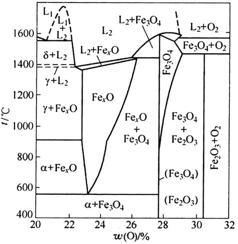
Figure 2.
Phase diagram of Fe-O [
The wustite should not be stable at low temperatures. When the temperature is lower than 570°C (843 K), FexO will be decomposed into Fe3O4 (Magnetite) and
3. Reduction thermodynamics
Here, reduction refers to capturing the oxygen combined with metal elements in the ore, which is the basic task to be completed in the smelting process. It uses a substance (reducing agent) with a stronger ability to combine with oxygen to break the chemical key of metal ions and oxygen ions in ore and release metal elements. The reducing agents, such as carbon (C), carbon monoxide (CO), and hydrogen (H2), are selected for industrial production.
Both production practice and scientific research have proved that no matter what reductant is used to reduce iron oxide, it changes from high-valence oxide to low-valence oxide step by step. In the laboratory, the hematite ball in the reduction process is rapidly placed in a neutral or inert atmosphere for cooling, and then its section is taken for observation. A distinct layered structure can be found. The core of the ball is unreacted, with a layer of Fe3O4 on the outside, a thin layer of wustite on the outside, and metal iron gradually thickened with the reaction on the outside. The semi-reduced ore samples obtained from the furnace during the dissection of the blast furnace also have the same shell structure.
To judge the degree of difficulty of various iron oxides being reduced by different reductants at different temperatures, the most basic basis is the graph of changes in the standard free energy of formation of various oxides with temperature, or the “oxygen potential graph.” The diagram of standard free energy of formation of iron oxide and oxide generated by relevant reductant is only involved in iron ore reduction, which is called the Ellingham diagram (Figure 3).
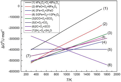
Figure 3.
Ellingham diagram.
According to the Ellingham diagram, the most stable of the three iron oxides is FeO. Simultaneously, FeO cannot be reduced by CO or H2 above 570°C (843 K).
3.1 Indirect reduction
Indirect reduction means that the reductant is gaseous CO or H2, and the product is CO2 or H2O.
The reactions listed have a common feature, that is, there is a gas phase before and after the reaction and its molecular number (i.e., volume) is unchanged. Under the condition that other substances participating in the reaction are pure solid, the equilibrium state of the reaction is not affected by the total pressure of the system. The equilibrium constant of the reaction can be expressed by
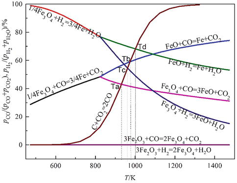
Figure 4.
Equilibrium iron oxide diagram reduced by CO, C, and H2.
From Figure 4, with the promotion of the reduction reaction, the high-valence oxides with high oxygen content are reduced into low-valence oxides with low oxygen content. The reduction reaction becomes more difficult, which is reflected in the requirements of
It also can be seen from Figure 4 that the slope of the curve is related to the thermal effect of the reaction. The exothermic reaction increases with temperature, and
CO and H2 have the same reduction capacity at 810°C (1083 K). When the temperature is lower than 810°C (1083 K), the reduction ability of CO is stronger than that of H2. If it is higher than 810°C (1083 K), the opposite is true. This can be explained by the equilibrium relation of water gas displacement reaction in the C▬O▬H system. The reaction formula is:
For blast furnace, the existence of water gas displacement reaction makes H2 have the effect of promoting CO reduction, which is equivalent to the catalyst of CO reduction reaction.
When the water gas displacement reaction is above 800°C, the reaction speed is quite fast, that is, once CO reduces from FeO to CO2, due to the existence of H2, it can be rapidly regenerated into CO to participate in the reduction.
Since this displacement reaction is a homogeneous reaction (reactants are all in the gas phase), at 750–800 K (477–527°C) in the blast furnace, under the catalysis of Fe, Cr, Ni, Mn, and other oxides, CO and H2O start to react, while at 1330 K (1057°C), the reaction can be carried out at a high speed without any catalyst, which can be considered as reaching an equilibrium state in the blast furnace.
In the high-temperature zone where the reduction capacity of H2 is stronger than that of CO, the superposition result of H2 reduction and water gas replacement is equivalent to the consumption of CO and the reduction of FeO, which improves the CO use efficiency. In the middle- and low-temperature regions where the reduction capacity of CO is stronger than that of H2, although H2 is superior to CO in kinetics, the amount of H2 involved in indirect reduction is not more than that of CO due to the restriction of thermodynamics. Therefore, the utilization ratio of H2 and CO in the blast furnace not only increases but also restricts each other.
We have already known that wustite is an oxide with an unstable oxygen content, and its reduction reaction equations are expressed as follows:
The equilibrium constants of the above reactions are expressed as follows:
It can be seen from the formulas that, for the wustite, when it is reduced by gaseous reductant, the equilibrium gas phase composition is not only a function of temperature but also a function of the oxygen content of the wustite.
The equilibrium diagrams of Fe▬O▬CO and Fe▬O▬H2 are shown in Figures 5 and 6.
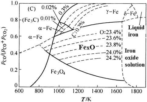
Figure 5.
Equilibrium diagram of Fe▬O▬CO [
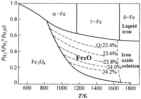
Figure 6.
Equilibrium diagram of Fe▬O▬H2 [
3.2 Direct reduction
Direct reduction means that the reducing agent is solid C and the product is CO.
In a blast furnace, the direct reduction does not mean that only the direct contact reaction between solid C and solid FeO can occur (except the reaction between FeO in liquid slag and solid C). On the contrary, due to the extremely poor contact conditions between the two solid phases, it is not enough to maintain the perceptible reaction rate. The actual direct reduction reaction is realized by the superposition of carbon dissolution loss reaction (C + CO2 = 2CO, Figure 4) and water gas reaction (H2O + C=CO + H2) and indirect reduction reaction.
Direct reduction mainly refers to the direct consumption of solid carbon. Another characteristic of this reaction is that it is strongly endothermic, and the thermal effect is up to 2717 kJ/kg.
Since this reaction only involves one gas phase product, its equilibrium constant can be expressed by the partial pressure of CO (
4. Reduction kinetics
The research on the reaction mechanism and quantitative law of the rate of gas reduction of solid iron ore has gone through a state of gradual perfection and approaching to reality from the shallow to the deep. In the late 1960s, most metallurgical workers tended to believe that the whole reduction process was composed of a series of interconnected subprocesses, and was often controlled not by a single subprocess but by two or more sub-processes. At different stages of the reduction process, the process control links may also be transformed. Due to different understandings of the role played by each process, a variety of reduction process mechanism models are proposed, such as unreacted core model, layered model, quasi-homogeneous model, and intermediate model.
Because it is of no practical significance to study the reduction kinetics of pure FeO, and the reduction of wustite to metal Fe is the most difficult and the most oxygen removal stage in the reduction process of single ore particles, the deoxidation process of Fe2O3 (hematite) and Fe3O4 is ignored, and it is believed that there is only one reaction interface. The following is a brief introduction to the “unreacted core model”.
According to the sequence of iron oxide reduction, the fact that the cross section of the single ore particles in the reduction process is layered, and the unreacted core gradually shrinks with the reaction process, the mathematical expression of the overall reduction rate is derived from the basic chemical thermodynamics and dynamics principles, taking into account all the processes of the whole reduction process.
Take the cross section of ore ball with layered structure in the reduction process (Figure 7), and assume that the secondary process of each link is as follows.
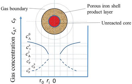
Figure 7.
Unreacted core model.
Reduction gas diffuses outside the boundary layer → Reduction gas diffuses inside the product layer → Reduction gas adsorbs at the reaction interface → Interface chemical reaction → Oxidation gas desorbs → Oxidation gas diffuses inside the product layer → Oxidation gas diffuses outside the boundary layer.
In order to simplify the mathematical treatment, (1) the ore particles are assumed to be regular spherical with radius of
Finally, the restore process is simplified into the following five sub-processes:
The molecules of the gas-reducing agent pass through the gas boundary layer (external diffusion) from the gas mainstream (gas concentration:
The gas-reducing agent molecules diffuse (can be called internal diffusion) through the porous reduction product (iron shell) layer to reach the outer surface of the unreacted core (i.e., the reaction interface), and the concentration further decreases to
The chemical reaction takes place on the interface, and the details, such as the adsorption of reducing gas molecules and the desorption of oxidation gas generated after the reaction, are ignored here.
After desorption of oxidized gas molecules, the concentration on the surface of unreacted nucleus is
The oxidation gas diffuses into the gas mainstream through the gas boundary layer, and the concentration decreases to
The change process of
The specific derivation process of the reduction rate mathematical model is ignored here, and only the formulas of the reaction rate are given as follows:
The general formula (13) of reaction rate can only be used for theoretical analysis of the parameters that affect the reduction rate. After transformation, the formula (14) expressed in measurable parameters can be used to test the experimental data to determine which process (or multiple processes) of an ore under different conditions becomes the controlling link of the reduction reaction.
5. Transformation of wustite in blast furnace
Once ore is added to the blast furnace, it will undergo a series of physical and chemical changes. The total residence time of ore in the blast furnace fluctuates between 5 and 8 hours. The gas-solid phase reduction process from high-valence oxide to wustite is completed in 1–2 h, and then half or more of the wustite is reduced to metallic iron in an indirect reduction way in 1–2 h. After entering the high-temperature zone higher than 1000°C (1273 K), only direct reduction can be carried out. Slag is formed after the furnace charge is heated to softening and melting temperature, and there is still a considerable amount of liquid wustite that needs to be reduced at a very fast speed by solid carbon or carbon dissolved in iron [1]. A more specific description of the FeO change process is described below [2].
The reduction process starts at temperatures of about 500°C (773 K) in the atmosphere of a reducing gas, that is, the blast furnace top gas. The reduction of hematite to magnetite takes place rather easily. The magnetite is further reduced by gas (CO and H₂) to wustite. All reduction is taking place by means of gas reduction (Fe₂O3 + CO → 2FeO + CO₂), and in this temperature range also for a small part by hydrogen reduction (Fe₂O3 + H₂ → 2FeO + H₂O). The gas reduction continues to a gas temperature above 1000°C (1273 K) and a reduction of iron oxide to a level of FeO0.5. The higher the temperature, the more H₂ contributes to the gas reduction. The gas reduction continues to rise until the temperature has risen to that where the coke reactivity reaction begins.
If the material starts to soften and melt (around 1100°C), the direct reduction reaction (FeO + C → Fe + CO) will take place. At that moment, the atomic ratio of O/Fe is slightly below 0.5 atom oxygen per atom of iron. In the case of natural gas injection, it can decrease to around 0.35 atom oxygen per atom of iron.
Softening and melting start at local chemical compositions with the lowest melting temperatures. This is where there are high local concentrations of SiO₂ and FeO. Internal migration of atoms will cause larger and larger parts of the particles to soften. The first internal “melts” of material will form at approximately 1100°C (1373 K) and will consist of gangue and to a large extent FeO, because at 1100°C (1373 K), the O/Fe ratio in the ferrous burden is 0.5 or lower. When gangue starts to melt, it will come into contact with the slag components of other parts of the ore burden and the slag composition will be averaged. This happens at high FeO concentrations.
The basicity of the remaining materials equals the basicity of the input materials. Figure 8 shows a simplification of the real situation in a blast furnace and shows a slag phase diagram with the three main components: CaO, SiO2, and FeO. It shows that slag melting starts at low temperatures, but that the basicity of the burden affects melting. As the FeO is reduced out of the primary melt, the slag liquidus temperature increases, but a much higher liquidus is seen for materials with a higher basicity.
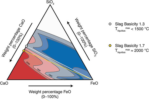
Figure 8.
Slag liquidus temperatures of CaO–SiO2–FeO. Slag melting starts at 60–70 wt% FeO in the structure. The yellow line indicates ferrous burden basicity (CaO/SiO2) of 1.5 and the white line 1 [
Since hydrogen can easily diffuse into a more solid structure, the hydrogen reduction continues after CO reduction has stopped. When the melts are heated further and start to drip, the melt consists of a blend of the gangue, FeO, and finely dispersed iron, which has not been separated from the melt. The first process in the “primary” melt is that the gangue loses its FeO. As soon as the FeO is removed and the primary melt flows over the coke, the iron starts to dissolve carbon from the coke, which lowers the melting temperature rapidly. As long as the slag contains FeO, the silicon in the hot metal will be oxidized back to SiO2 and the FeO in the slag reduced to Fe by coke or saturated carbon in molten iron. At the wall of the furnace, the root of the cohesive zone is located a small distance above the tuyeres, while in the center the cohesive is located higher in the furnace. As a consequence, the slag formed at the wall will have relatively high FeO and the hot metal formed at the wall will have low silicon, while the hot metal formed and dripping down in the center of the furnace will have high silicon. The content of FeO in the final slag is less than 0.5 wt%, and the total recovery rate of Fe is more than 99.7%.
6. Reduction of wustite by purehydrogen in future
The application of hydrogen technology provides a new idea for the steel industry to achieve the goals of carbon peaking and carbon neutralization, especially in China. Hydrogen metallurgy has become the clean, efficient, and pollution-free steelmaking technology direction of exploration in different countries.
Zhang Jianliang
Guo Peimin et al. have promoted the development of the pure-hydrogen reduction process by the methods of theoretical analysis and calculation to discuss the industrial application prospect and key issues in basic theory and application. Heating hydrogen to the target temperature is an important factor to ensure the reduction of iron oxide. The discussion on the control step should pay attention not only to the reduction reactions but also to the heat transfer. This basic issue is directly related to the design of hydrogen reduction reactors, thus indicating the need for further studies. The important factors affecting the smooth operation of the hydrogen reduction process includes preparation of high-quality oxidized pellets, preheating of hydrogen, design of reduction device, composition and pressure of reducing gas, and security issues [9, 10, 11, 12, 13, 14, 15, 16, 17, 18, 19, 20].
7. Conclusions
Based on previous research, the chapter summarizes the reduction thermodynamics and kinetics of wustite by C, CO, and H2. When the temperature is lower than 810°C (1083 K), the reduction ability of CO is stronger than that of H2. If it is higher than 810°C (1083 K), the opposite is true. Especially, the reduction process of wustite in blast furnace is discussed in detail. Wustite is the most difficult to be reduced in the three iron oxides. In the future, research on the reduction by pure hydrogen in ironmaking will also be the key to realize carbon neutrality. When the temperature is 1173 K, according to calculation, considering the theoretical amount and the chemical balance of the reduction reaction, the amount of hydrogen required to be put into the reactor is 952 Nm3/t Fe.
Acknowledgments
This work was funded by “Basic Research Project of Education Department of Liaoning Province, No. LJKMZ20221688”, “National Natural Science Foundation of China, No. 52074086”, “Entrepreneurship and Innovation Program of Enterprise and Doctor by Yingkou, No. 202116 and No. 202010”, “Key R&D Project of Liaoning Province, No. 2020JH2/10100019 and No. 2022JH2/101300124”. And also the special thanks to the projects, which are sponsored by Liaoning BaiQianWan Talents Program and Liaoning Innovation talents.
Appendices and nomenclature
standard Gibbs free energy, J/mol
standard enthalpy change of reaction, J/mol
equilibrium constant of reaction
partial pressure of CO2
partial pressure of CO;
absolute temperature, K;
partial pressure of H2O
partial pressure of H2
volume fraction of CO2
volume fraction of CO
volume fraction of H2O
volume fraction of H2
activity of oxygen atom
original radius of ore ball
radius of unreacted core
reducing gas concentration in the gas mainstream, mol/m3
reducing gas concentration on the surface of the ball, mol/m3
reduction gas concentration on reaction interface at any time, mol/m3
product gas concentration on reaction interface at any time, mol/m3
product gas concentration on the surface of the ball, mol/m3
product gas concentration in the gas mainstream, mol/m3
reducing gas concentration in equilibrium, mol/m3
reducing gas concentration, mol/m3
product gas concentration, mol/m3
the overall reaction rate, mol/s
mass transfer coefficient in boundary layer, m/s
effective diffusion coefficient of gas in micropores of the ball, m2/s
reaction rate constant, m/s
reduction degree
density of oxygen in the ball, kg/m3
References
- 1.
Xiaoliu W, Shengli W, editors. Ferrous Metallurgy (Ironmaking Part). 3rd ed. Beijing: Metallurgical Industry Press; 2013. 104 p; 105 p; 108-109 pp. 127-128 pp - 2.
Geerdes M, Chaigneau R, Kurunov I, et al. Modern Blast Furnace Ironmaking : An Introduction. 3rd ed. Amsterdam: IOS Press; 2015. pp. 128-131 - 3.
Jianliang Z, Yang L, Zhengjian L, et al. Isothermal kinetic analysis on reduction of solid/liquid wustite by hydrogen. International Journal of Minerals , Metallurgy and Materials. 2022; 29 :1830-1838. DOI: 10.1007/s12613-022-2518-0 - 4.
Katayama H, Taguchi S, Tsuchiya N. Reduction of iron oxide in molten slag with H 2 gas. Tetsu-to-Hagane. 1982; 68 :2279 - 5.
Ban-Ya S, Iguchi Y, Nagasaka T. Rate of reduction of liquid wustite with hydrogen. Tetsu-to-Hagane. 1984; 70 :1689 - 6.
Hayashi S, Iguchi Y. Hydrogen reduction of liquid iron oxide fines in gas-conveyed systems. ISIJ International. 1994; 34 :555 - 7.
Nagasaka T, Hino M, Ban-Ya S. Interfacial kinetics of hydrogen with liquid slag containing iron oxide. Metallurgical Materials Transaction B. 2000; 31 :945 - 8.
Seftejani MN, Schenk J. Kinetics of molten iron oxides reduction using hydrogen. In: International Congress on Science and Technology of Steelmaking. Venice; 2018 - 9.
Lei W, Peimin G, Lingbing K, et al. Industrial application prospects and key issues of the pure-hydrogen reduction process. International Journal of Minerals , Metallurgy and Materials. 2022; 29 :1922-1931. DOI: 10.1007/s12613-022-2478-4 - 10.
Spreitzer D, Schenk J. Reduction of iron oxides with hydrogen—A review. Steel Research International. 2019; 10 :1900108 - 11.
Xu H, Zou ZS, Zhou YS, Li ZY, Yu AB. Preliminary numerical simulation of shaft furnace process for DRI production. Journal of Materials Metallurgy. 2009; 8 :7 - 12.
Zhao ZW, Kong FL, Tong LG, Yin SW, Xie YR, Wang L. Analysis of CO 2 emission reduction path and potential of China’s steel industry under the “3060 target”. Iron Steel. 2022; 57 :167 - 13.
Xu ZY, Wu BC. Simulating study on direct reduction of iron ore by midrex process. Gangtie. 1987; 22 :8 - 14.
Bai MH, Fu YX. Design method of reduction segment parameters of the gas-based direct reduction shaft furance. Journal of Iron and Steel Research. 2015; 27 :21 - 15.
Li F, Chu MS, Tang J, Liu ZG. Environmental impact analysis of hydrogen shaft furnace-electric furnace process. China Metallurgy. 2021; 31 :104 - 16.
Sarkar S, Bhattacharya R, Roy GG, Sen PK. Modeling MIDREX based process configurations for energy and emission analysis. Steel Research International. 2018; 89 :1700248 - 17.
Wang XN, Fu GQ, Li W, Zhu MY. Numerical simulation and optimization of flash reduction of iron ore particles with hydrogen-rich gases. Powder Technology. 2020; 366 :587 - 18.
Hamadeh H, Mirgaux O, Patisson F. Detailed modeling of the direct reduction of iron ore in a shaft furnace. Materials (Basel). 2018; 11 :1865 - 19.
Valipour MS, Motamed Hashemi MY, Saboohi Y. Mathematical modeling of the reaction in an iron ore pellet using a mixture of hydrogen, water vapor, carbon monoxide and carbon dioxide: An isothermal study. Advanced Powder Technology. 2006; 17 :277 - 20.
Kazemi M, Pour MS, Du SC. Experimental and modeling study on reduction of hematite pellets by hydrogen gas. Metalluric Materials Transaction B. 2017; 48 :1114