Open Access is an initiative that aims to make scientific research freely available to all. To date our community has made over 100 million downloads. It’s based on principles of collaboration, unobstructed discovery, and, most importantly, scientific progression. As PhD students, we found it difficult to access the research we needed, so we decided to create a new Open Access publisher that levels the playing field for scientists across the world. How? By making research easy to access, and puts the academic needs of the researchers before the business interests of publishers.
We are a community of more than 103,000 authors and editors from 3,291 institutions spanning 160 countries, including Nobel Prize winners and some of the world’s most-cited researchers. Publishing on IntechOpen allows authors to earn citations and find new collaborators, meaning more people see your work not only from your own field of study, but from other related fields too.
To purchase hard copies of this book, please contact the representative in India:
CBS Publishers & Distributors Pvt. Ltd.
www.cbspd.com
|
customercare@cbspd.com
Gantry cranes are widely used in industry for load transfer, but increasing the trolley or rail speed to move loads quickly leads to excessive swaying. This swaying must be minimized before any loading or unloading can occur, a process that consumes time and can stress the hoist, damage surrounding objects, and jeopardize the payload. In the context of gantry crane control, the first step is to develop an optimal motion planner to generate a reference command. Then, a Fuzzy-PID controller is employed. This controller is designed to adapt to real-time system changes, making it well-suited for the gantry crane’s nonlinear model, which conventional PID controllers struggle with. The Fuzzy-PID controller’s nonlinear nature is particularly advantageous for managing the highly nonlinear gantry crane model. It excels, especially in the presence of external disturbances, outperforming traditional PID controllers. The fuzzy-PID controller is superior in optimizing sway angle tracking and achieving better position control compared to conventional PID controllers, offering enhanced performance in gantry crane operations.
Addis Ababa Institute of Technology, Addis Ababa, Ethiopia
Hafte Tkue
Addis Ababa Institute of Technology, Addis Ababa, Ethiopia
Yalemzerf Getnet
Addis Ababa Institute of Technology, Addis Ababa, Ethiopia
*Address all correspondence to: kassahunberisha@gmail.com
1. Introduction
The most common cranes are bridge (overhead) cranes, gantry cranes, boom cranes, and tower cranes. Transporting the load as fast as possible without causing any excessive swing at its final destination/position is the main purpose of controlling a gantry crane. However, many of the gantry cranes results in a swing motion when there is a payload they stopped suddenly for a fast motion of the gantry crane [1].
The swing angle (motion) can be scheduled and the reduced to minimum but it becomes time consuming. Furthermore, the gantry crane operation needs a skillful operator to control the sway motion manually to stop the swing at the predetermined position of the gantry crane immediately [2]. Different kinds and degrees of accident in human beings and the surrounding will occur if the control mechanism of a gantry crane is poor [3]. Therefore, the performance of this equipment may be limited by the fact that the loads move in a pendulum-like manner, which is hazardous to industrial security [4].
The main objective of this paper are to design fuzzy-PID Controller for position and anti-sway control of the gantry crane and planning the motion that a gantry crane followed through its operation.
This system has great application in almost all industries many scholars have been studying in this area. Among them a some of articles are reviewed as follows.
In [5], modeling and nonlinear control of gantry crane using feedback linearization method is presented. In this paper, a dynamic model of gantry crane is developed using a powerful method called a Lagrange method. The State feedback linearization technique is applied for the model linearization and its weaknesses are reviewed. To solve these problems, the state feedback gain matrix is calculated using the Linear Quadratic Regulator method and results are fully investigated. Nonetheless, in the linearized model he used, it is difficult to investigate the nonlinear characteristics of the gantry crane. And also, the researcher does not consider the motion planning of the gantry crane. From a system response of the gantry crane, the settling time is long and the rise time is slow. One can notice it is not good enough and requires further demonstration.
In [6], position regulation and sway control of a nonlinear gantry crane system had proposed. With this paper, the controller used is Proportional plus derivative controller (PD) for both the gantry crane’s position and sway angle. Having said that, the controller gains KP and KD are manually tuned. Also, the motion planning is not studied. The system response in terms of its overshoot is high and rise time is also slower.
In [7], optimal PID controller of automatic gantry crane control using particle swarm optimization (PSO) is presented. The controller used is PID and the particle swarm optimization (PSO) is used to auto tune the PID gains [8]. The good features of this paper are the PID controllers KP, KD, and KI are tuned automatically using the PSO algorithm. The drawbacks of this paper are the motion trajectory is unknown which means not studied and the system response is poor. Also, the system response is not robust.
In [9], fuzzy control scheme for the gantry crane position and load swing control have proposed. The researchers proposed a fuzzy controller for positioning and anti-swing control scheme of the gantry crane. The linearized gantry crane system model which does not represent the nonlinear nature of the crane system dynamics and the fact that the linearized mathematical model mostly does not provide the dynamic behavior of the real system well. The system responses are satisfactory but the consideration of cart optimal motion planning is not included.
In [10], the model predictive control of gantry crane with input nonlinearity compensation studied. The paper evaporates the application of a nonlinear model predictive control method for controlling gantry crane systems. The drawbacks of this paper are that the system’s mathematical model is linear and the motion plan trajectory is not considered. The response of the gantry crane to its sway angle is not settling for a long time to its equilibrium points and the steady state is also not minimum.
In [11], the paper titled pole placement control of a 2D gantry crane system with varying pole locations is considered. In this paper, the model of the system linearized model, and the controller used is a pole placement controller which is designed with three poles located at different locations on the left-hand side of the s-plane. Due to highly nonlinearity of gantry crane, controlling the position and sway using manual method of varying location of poles is not advisable criteria. Also, the model does not specify the real worlds specification due to many assumptions while linearizing the model. Again, the motion planning trajectory is not considered. The system responses using pole placement method showed that a higher overshoot and longer time to settle. Therefore, nonlinear controllers are the best option for nonlinear systems.
In [4], the closed-loop schemes for position and sway control of a gantry crane system is studied. This paper the gantry crane control method presented are the performance of linear quadratic regulator (LQR) and proportional plus integral plus derivative control schemes for both payload sway control and trolley position tracking. In an approximate model in which many system parameters are assumed helps the researcher from considering the nonlinearities and removes system modeling complexity but the response is not as acceptable as the true model. Not only this, but also the motion planning or trajectory planning is not considered. Again the system response is not adequate, which means the rise time is slow and higher overshoot/undershoot is detected but the steady state error is very good.
1.1 Problem of statement
Gantry crane is a common type of crane that used to transfer the payload from one position to another desired position. During the load the gantry crane behaves like a pendulum during the transportation that process sway around the destination position. If the sway reaches a final critical limit, the crane process must be stopped until the sway disappears otherwise the situation will lead to accident, injury, or fatality. Crane operation in general requires quick transferring of the load to the desired position without excessive swaying.
Unfortunately, fast transporting heavy loads would result in the excessive swaying of the load. Moreover, the swaying of the load can also be affected by external environmental disturbances like wind and parameter uncertainty in the system. Because of uncontrolled payload swing dynamics, it is necessary to have an anti-sway controller installed in a gantry crane system to suppress the swaying without human interaction. To optimize between fast transporting and less swaying, optimal motion tracking algorithms are a great tool to use.
1.2 Proposed solution
Using optimal motion tracking, a desired velocity profile trajectory that should be tracked by cart/bridge will be produced. Different types of controllers can be used to better track the reference velocity profile signal by the cart or the bridge. The highly nonlinear crane dynamics are bettered controlled with a nonlinear control scheme. Hence, Fuzzy-PID controller is proposed for this system since it has nonlinear nature, and is highly robust to parameter variation, and exploits the benefit of both Fuzzy and PID controllers.
1.3 Motivation and contribution
Since cranes are under actuated oscillatory systems. Many types of research have been done in the area of controlling gantry cranes, aiming at the reduction of positioning errors and traveling time. Since they do not need feedback sensors for measuring the states of the crane, Open-loop strategies are the most used by far for their cheapness. Due to the parameter uncertainties and disturbances we propose an optimal motion planner is an open-loop algorithm that will produce an ideal trajectory that should be tracked by the trolley/bridge of the gantry crane for best performance. This makes optimal motion planning and Fuzzy-PID controller complement each other in solving the problems in the gantry crane. Moreover, the highly nonlinear model of gantry crane is better controlled with a nonlinear controller like Fuzzy-PID controller.
1.4 Paper organization
Section 2 presents gantry crane modeling, which will describe the basic operation of gantry crane, structure of gantry crane, and mathematical model of gantry crane. Section 3 describes the design of the conventional controller, PI and the fuzzy controller, and fuzzy-PID controller. In Section 4 shows the simulation results result and also Section 5 compates the discussion on the proposed controller and compare them with the conventional controller. Finally, the performance of each controller is measured. In Section 6 draws the conclusions on the paper and also in Section 7 recommendation to further works is presented.
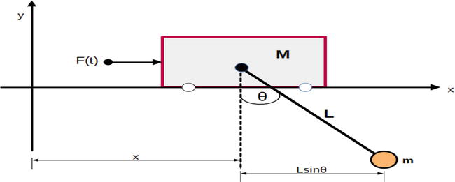
Since the gantry crane has two movable parts which are the rail and the trolley (cart), its motion dynamics can be mathematically modeled in two separate parts. A trolley is an electromechanical machine installed on the rail that traverses long Y-axis shown in Figure 1. The trolley carries a load attached to the hoist along the rail. The rail carries the trolley and moves along the X-axis. With the movement of the rail and the cart, we can reach any point in the x-y plane inside the working region of the crane [12].
Figure 1.
Gantry crane free body diagram.
2.1 Mathematical model of the trolley/cart movement
When translational force is exerted on the cart by a motor, the cart moves along the Y-axis and this creates swing dynamics of the load along the Y-axis [13]. This swaying of the load along the Y- axis is measured as an angle which is denoted by in Figure 1. While modeling the cart movement, we have to describe the dynamics of the cart position denoted by y and the load swaying angle (θ). The Lagrangian method is used here since it eases the complexities of the steps for gantry crane [12]. Lagrangian function L is described as:
L=T−VE1
Where T and V are the Kinetic and potential energy of the entire system. The Lagrangian equation is given by:
ddtdLdu̇i−dLdu̇i=FiE2
Where ui=xθT is generalized displacements and Fi is an external force. The kinetic energy of the gantry crane is
T=12Mẋ2+12mẋp2E3
The potential energy of the gantry crane is
V=mgẏpE4
Plugging into fundamental langrage equation to get equation of motion in x-component of gantry crane gives
M+mx¨+mLθ¨cosθ−mLθ̇2sinθ=FE5
For the rotational component of the gantry crane the Lagrange equation gives
mx¨cosθ+mLθ¨+mgsinθ=0E6
Now, by applying small angle approximation of sinθ≈θ,cosθ≈1, the equation of motion for the x-component in Eq. (7) and rotational motion in Eq. (8) are expressed.
x¨=mgθ+mLθ̇2θ+Fm+MθE7
θ¨=−x¨+gθLE8
2.2 Mathematical model of the rail movement
When a force acts on the stationary rail, the rail moves along the x-axis as shown in the coordinates in the figure and this causes the load to sway along the x-axis. This swaying can be measured as an angle as shown in Figure 1. To describe the mathematical model of the rail movement, we have driven the dynamics of the position of the rail denoted by X and the load swaying caused by it denoted by θ. Other than that, we will follow the same fashion as into driving the dynamics of the rail movement.
2.3 Optimal motion planning
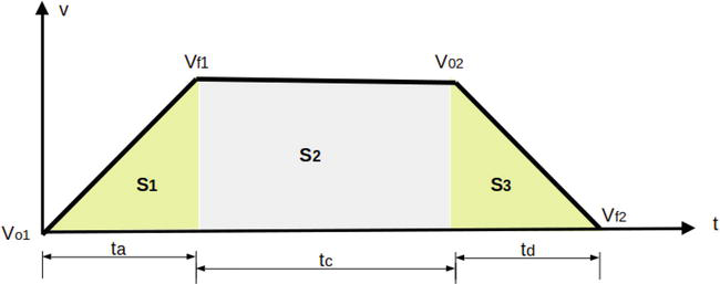
In this paper, trapezoidal velocity-time curve shown Figure 2 is used as reference of the position and sway angle of the gantry crane. For the designed optimal motion planning the sway angle at the destination can be lowered to zero.
Figure 2.
Trapezoidal velocity plan.
2.3.1 Trajectory planning
For the 2D gantry crane system the reference signal can be used many types of test signals but in order for the accuracy and safety of operation it is better to plan the trajectory of the reference to track the output of the system. In this paper, trapezoidal velocity – time curve shown in Figure 2 is used as reference of the gantry system control system. But, the entire shapes of loads to be transported to and/or from are not the same in the practical application. For simplicity it is assumed that acceleration time ta is equal to the deceleration time td in the areas S1 and S3 respectively and the total displacement is expressed in Eq. (9):
S=S1+S2+S3E9
Where S1, S2, S3 are the area of acceleration, constant speed, and deceleration time zones. At the initial state all parameters are assumed at equilibrium. i.e. sway angle θ=0, velocity Vi=0, acceleration ai=0, and applied force Fi=0.
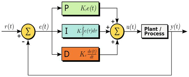
The classical PID controller is the well known form of feedback controller and became the standard tool when process control emerged in the 1940s [14]. In process control today, more than 95% of the control loops are of PID type, most loops are actually PI control. PID controllers are today found in all areas where control is used [15]. The PID controller attempts to minimize the error value over time by adjustment of a control variable to a new value determined by a weighted sum [4].
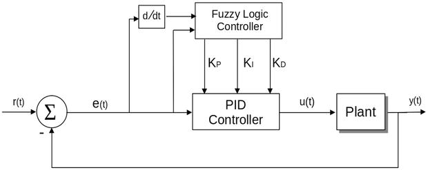
ut=Kpet+KI∫0τeτdτ+KDddtetE10
Where KP,KI,andKD all non-negative, denote the coefficients for the proportional controller, integral controller and derivative controller terms, respectively Figure 3.
Figure 3.
Structure of a PID controller.
3.2 Fuzzy logic controller
Fuzzy control provides a formal methodology for representing, manipulating, and implementing a human’s heuristic knowledge about how to control a system. In fuzzy logic, basic control is determined by a set of linguistic rules which are determined by the system. In fuzzy logic control method the mathematical modeling of the system is not required. The input parameters are fuzzified in the fuzification module and represented in fuzzy set notations as membership functions and “IF⋯THEN⋯” rules produce output signal and these signals are deffuzzified to crisp values in the diffuzification module [16].
3.2.1 Fuzzification
The Fuzzification module transforms the physical values of the input reference signal into a normalized fuzzy subset consisting of a subset for the range of the input values and an associate membership function describing the degrees of the input belonging to the given ranges.
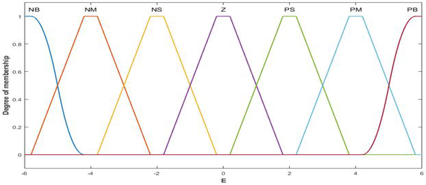
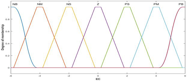
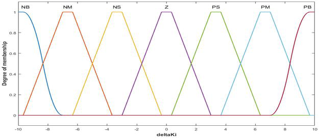
The error and rate of change of error are defined by linguistic variables such as negative big (NB), negative medium (NM), negative small (NS), zero (Z), positive small (PS), positive medium (PM), and positive big (PB) characterized by triangular membership functions shown in Figures 4 and 5 respectively. The output is also defined by seven linguistic variables characterized by membership functions given in Figure 6.
Figure 4.
Error membership function.
Figure 5.
Derivative of error membership function.
Figure 6.
Output membership function.
3.2.2 Decision making
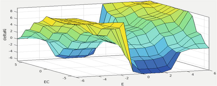
Mamdani fuzzy inference system is well-suited to human input, intuitive, and can easily obtain the relationship between its inputs and output. In this paper, triangular membership function is used because of simplicity. The “IF⋯THEN⋯” principles characterize a fuzzy inference system (FIS) by associating the output to the inputs (Figure 7) [17].
Figure 7.
Surface of membership function.
The output is produced by fuzzy sets and fuzzy logic operations by evaluating all the rules, Table 1 which have 49 rules for the seven 7 linguistic variables and the combination of rules are expressed as follows. Where E represents for error and Δ E for change in error.
E
NB
NM
NS
Z
PS
PM
PB
NB
PB
PB
PB
NM
NM
Z
Z
NM
PB
PB
PM
NS
NS
Z
PS
NS
PB
PB
PS
Z
Z
PS
PB
ΔE
Z
PB
PM
PS
Z
PS
PM
Z
PS
PM
PS
Z
Z
PS
PM
PB
PM
PS
Z
NS
NS
PM
PB
PB
PB
Z
Z
NM
NM
PB
PB
PB
Table 1.
Rule base of the fuzzy controller.
3.2.3 Defuzzification
Deffuzification is the process of converting the controller outputs in linguistic labels represented by fuzzy set to crisp values. The final crisp output value from the fuzzy logic controller depends on the type of Deffuzification method used to compute the outcome values corresponding to each label. The input for the Deffuzification process is the aggregated output fuzzy set from the rule base of the fuzzy logic controller and the output is a single crisp number [18].
The rule base outcomes of the fuzzy logic inference mechanism after they have been logically added and then compute a value that will be the final output of the fuzzy controller are examined by the Deffuzification module. The fuzzy controller then sends control signal to the output module to control the plant. Thus, during Deffuzification, the module converts the fuzzy output signals into a real life crisp value [19].
3.3 Fuzzy-PID controller
Fuzzy logic controller is one of the nonlinear controllers that can be used to control gantry cranes. In comparison to the classical PID controller, fuzzy logic controller is a non-linear controller that can provide good performance under the parameters uncertainties and disturbances. The fuzzy logic controller is preferable for systems having cumbersome mathematical modeling and calculations [20]. In Fuzzy-PID controller, the error and rate of change of error signals are passed through the PID controller. These signals are processed by the fuzzy logic controller and their magnitudes are brought to a range desirable for input to the designed PID controller. Fuzzy-PID controller is the combination of conventional PID controller and fuzzy logic controller in which hybrid controllers are expected to improve the performance of nonlinear systems like gantry crane. Due to the nature of the gantry crane (which is non-linear) and the exact condition of the fault will happen to the system is random, the PID controller is not recommended alone. Therefore, good features of PID controller and fuzzy logic controller makes the system control strategy better (Figure 8).
In the simulation result of this paper, the optimal motion planning is planned using velocity trajectory path for the reference signal then the Fuzzy-PID controller is designed and finally the result is simulated as shown in the upcoming figures.
In this paper, the PID controller and Fuzzy-PID controller are simulated and compared with respect to the parameters of the gantry crane both sway angle and position. The optimal motion planning is used to track the output of the gantry crane same as the reference with minimized disturbances (Figure 9).
Figure 9.
The motion planned velocity trajectory path for reference signal.
4.1 Simulation results using PID controller
For the designed optimal motion planned reference of the gantry crane the parameters of the PID controller KPKIandKD are tuned from the toolbox of the MATLAB.
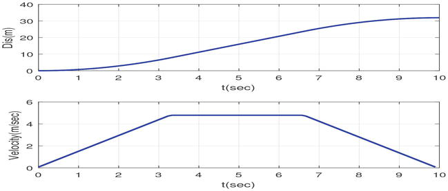
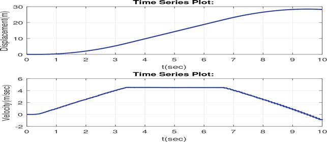
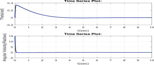
The velocities of the cart and payload increases linearly until desired maximum velocity is reached. After attaining their respective maximum velocity they moves with constant velocity for a certain time, then it starts decreasing its velocity until it approach to zero as shown Figure 10. The designed optimal motion planning of a 2D gantry crane of reference velocity of the cart and the load looks like as Figure 10 that tracks the trapezoidal curve shown in Figure 9. Figure 11 shows that the settling time of sway angle of the gantry crane under the classical PID controller is a long time. Due to the nonlinearity features of the gantry crane, the crane will not arrive its predetermined time under classical PID controller.
Figure 10.
The trajectory path tracking of gantry crane PID controller.
Figure 11.
The sway angle and angular velocity of the payload gantry crane using PID controller.
4.2 Simulation results using fuzzy-PID controller
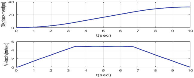
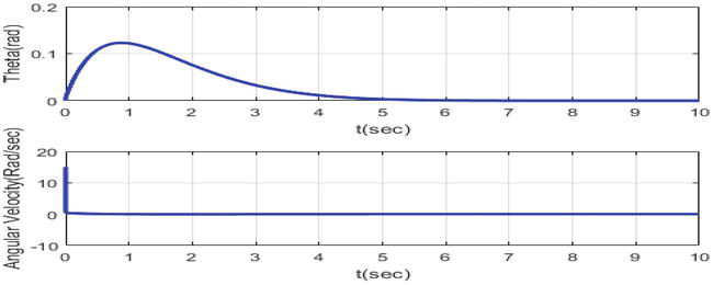
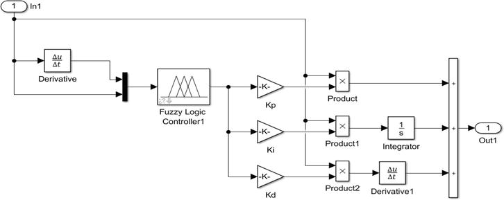
In Fuzzy-PID controller simulation, the values of the PID controller gains KPKIandKD are updates and evaluated from the rule base of the fuzzy logic controller. So, when any parameters are changing or disturbances are added into the system the fuzzy logic controller updates the values of the classical PID controllers KPKIandKD. Therefore, classical PID controller alone is not efficient in the presence parameter variations and uncertainties. So, fuzzy-PID Controller can to handle parameter uncertainties and disturbances and the fuzzy-PID controller is depicted in Figure 12. From the simulation results, the Fuzzy-PID controller has very small time required to settle about the sway angle compared to PID controller. Therefore, fuzzy-PID controller have a better sway angle tracking performance as compared to classical PID controller shown above (Figures 13 and 14).
Figure 12.
Simulation diagram of fuzzy-PID controller.
Figure 13.
The trajectory path tracking of gantry crane using fuzzy-PID controller.
Figure 14.
The sway angle and angular velocity of the payload of gantry crane using fuzzy-PID controller.
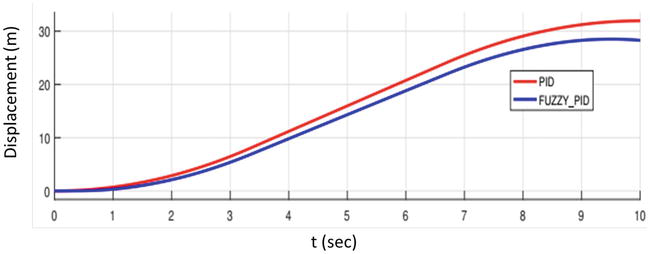
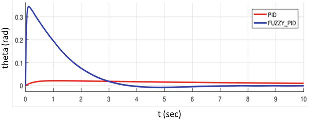
From the simulation results, the position control of the gantry crane using PID controller and fuzzy-PID controller are compared. According to the simulation result the PID controller is better in position control of the gantry crane with respect to the path tracking of the gantry crane. According to the simulation result the both the PID controller and fuzzy-PID controller are almost similar in velocity control of the gantry crane with respect to the path tracking of the gantry crane. According to the simulation result the fuzzy-PID controller is much better than that of PID controller in angular velocity control of the gantry crane with respect to the path tracking of the gantry crane. Generally, for the control of position and velocity control of a gantry crane PID controller is better but, for the sway angle control and angular velocity control fuzzy-PID controller is better than that of classical PID controller (Figures 15 and 16).
In this paper, the modeling and simulation of gantry crane controlled by fuzzy-PID Controller have been developed. From the simulation results, during transportation of the payload time efficiency is improved and ensured the safety of the position and sway of the gantry crane. The planned motion of the references of the gantry crane are followed by the designed controllers with minimum time and with small sway angle of the 2D gantry crane. Finally, optimal reference velocity tracking performance is used to compare the performances of the classical PID controller and Fuzzy-PID controller. The simulation result of fuzzy-PID controller has smaller sway angle as compared to classical PID controllers. Therefore, fuzzy-PID logic controller has better performance on the position and sway angle control.
In this paper, fuzzy-PID control systems and motion planning are proposed, designed, analyzed, and simulated using MATLAB. For the future work this paper can be done in different advanced controllers and other planning methods. Using intelligent control methods like artificial intelligence, reinforcement learning methods will be the best data training methods of gantry crane sway control and position controls. Since controlling the gantry crane with real data’s will be good controlling mechanism. Not only the controller but also the dynamics of controllers also will be extended to three dimensional (3D) model of gantry crane.
References
1.Ahmad M, Nasir A, Najib M, Ishak H. Anti-sway techniques in feedback control loop of a gantry crane system a comparative assessment of pd and pd-type fuzzy logic controller. In: 2009 4th IEEE Conference on Industrial Electronics and Applications. X’ian, China: IEEE; 2009. pp. 2483-2487
2.Ajayan M, Nishad PN. Vibration control of 3d gantry crane with precise positioning in two dimensions. In: 2014 Annual International Conference on Emerging Research Areas: Magnetics, Machines and Drives (AICERA/iCMMD). Kottayam, India; 2014. pp. 1-5
3.Ahmad M, Zulkifely Z, Zawawi MA. Experimental investigations of input shaping schemes for sway control of a gantry crane system. In: 2010 Second International Conference on Computer and Network Technology. Bangkok, Thailand; 2010. pp. 483-486
4.Alhassan A, Danapalasingam KA, Shehu M, Abdullahi A, Tijjani A. Closed-loop schemes for position and sway control of a gantry crane system. International Journal of Simulation Systems, Science and Technology. 2016;17:1
5.Omidi E. Modeling and nonlinear control of gantry crane using feedback linearization method. arXiv Preprint. 2014;5
6.Çakan A, Onen U. Position regulation and sway control of a nonlinear gantry crane system. International Journal of Scientific and Technology Research. 2016;5:121-124
7.Solihin MI, Wahyudi W, Kamal MAS, Legowo A. Optimal pid controller tuning of automatic gantry crane using pso algorithm. In: 2008 5th International Symposium on Mechatronics and its Applications. Amman, Jordan; 2008. pp. 1-5
8.Åström K, Hägglund T. Advanced PID Control. United States: ISA-The Instrumentation, Systems, and Automation Society; 2006
9.Popadic T, Kolonic F, Poljugan A. A Fuzzy Control Scheme for the Gantry Crane Position and Load Swing Control. Vol. 6. University of Zagreb; 2006
10.Su S, Nguyen H, Jarman R, Zhu J, Lowe D, McLean P, et al. Model predictive control of gantry crane with input nonlinearity compensation, world academy of science. Engineering and Technology. 2009;3:899-903
11.Bashir NM, Bature AA, Abdullah AM. Pole placement control of a 2d gantry crane system with varying pole locations. Applications of Modelling and Simulation. 2018;2:8-16
12.Park E, Martinez C. Motion Design Problem for a Gantry Crane. California State University Fullerton; 11 Jul 2021. pp. 4-6
14.Schleicher M, Blasinger F. Control Engineering: A Practical Guide. Measurement - Control - Recording. JUMO; 2006
15.Nise S. Nise’s Control Systems Engineering. United States: Wiley; 2010
16.Guanrong CT. Introduction to Fuzzy Sets, Fuzzy Logic, and Fuzzy Control Systems. United States: CRC Press; 2000
17.Ahmad AM, Mohamed Z. Hybrid fuzzy logic control with input shaping for input tracking and sway suppression of a gantry crane system. American Journal of Engineering and Applied Sciences. 2009;2:241-251
18.Allam E, Elbab HF, Hady M, Abouel-Seoud S. Vibration control of active vehicle suspension system using fuzzy logic algorithm. Fuzzy Information and Engineering. 2010;2(4):361-387
19.Zadeh L, Klir G, Yuan B. Fuzzy Sets, Fuzzy Logic, and Fuzzy Systems: Selected Papers. World Scientific; 1996
20.Simanjalam KR. Position and Anti-Sway Control of a Gantry Cranesystem Using Fuzzy-Tuned Pid Controller [Thesis]. Malaysia: University Teknologi Malaysia; Jun 2012
Written By
G. Kassahun Berisha, Hafte Tkue and Yalemzerf Getnet
Submitted: 17 June 2023Reviewed: 22 June 2023Published: 14 November 2023
 Open access peer-reviewed chapter