 Open access peer-reviewed chapter
Abstract
Arsenic is a highly toxic element in coal and one of the representative toxic trace metals emitted from coal-fired power plants, which is mainly converted into As2O3 vapor during the combustion process of coal. When absorbed by the body, arsenic can cause arsenic poisoning, which not only causes metabolic disorders and subsequent neurotoxicity in the body but also retards growth in young children. Arsenic is of increasing concern due to its bioaccumulation and potential carcinogenicity. This chapter describes the characteristics of arsenic emissions from coal-fired power plants and the various control technologies, including pre-, in-, and post-combustion control technologies. It also provides an outlook on future technological developments and provides theoretical guidance for controlling arsenic in flue gas.
Keywords
- arsenic
- technology
- As2O3
- coal-fired power plants
- control
1. Introduction
As people’s awareness of environmental preservation increases, the effects of heavy metal pollution on the environment have drawn considerable attention [1, 2, 3]. One of the heavy metal contaminants with high toxicity, bioaccumulation, and carcinogenicity is arsenic, a semi-volatile trace element [4, 5]. The majority of the As produced by coal combustion migrates into the flue gas as As2O3 vapor, some of which may interact with fly ash particles to form solids [6]. Dust collectors can catch the majority of the As that congeals in fly ash particles [7]. As poses a major health risk, when a small amount of it escapes into the atmosphere as tiny particles and vapors [8]. Additionally, in selective catalytic reduction (SCR) systems, arsenic vapor can interact with catalysts, causing these catalysts to malfunction [7]. In recent years, many researchers have investigated the type, content, and volatile properties of arsenic in coal. Pyrite, organic arsenic, and arsenate, which also contain arsenate, are the three primary forms of arsenic found in coal. Arsenate, on the other hand, is extremely stable and typically decomposes at rather high temperatures, whereas exchangeable and organically bound arsenic evaporates rapidly during the devolatilization of coal. And researchers have developed a number of techniques to control arsenic in the flue gas of coal-fired power plants. These include precombustion-, in-combustion-, and post-combustion technologies. The most common application today is the post-combustion removal of arsenic from coal-fired power plant flue gasses through the combined action of air pollution control equipment and sorbents. In addition, photocatalysis has shown great potential as a rapidly developing pollutant treatment method in recent years, with its low cost, simple process, nonpolluting nature, and recyclability. The removal of gaseous arsenic in flue gas is expected to be a new direction and many photocatalysts, including In2S3/g-C3N4, CoS/g-C3N4, Bi4O5I2/g-C3N5, etc., have been developed by Wu et al. for investigating the removal of arsenic, mercury, and other pollutants from coal-fired flue gas. It provides theoretical guidance for the photocatalytic removal of arsenic from coal-fired flue gas.
2. Review of arsenic pollutants in coal-burning flue gas
2.1 Properties and hazards of arsenic
Elemental arsenic has a melting point of 817°C at atmospheres. When heated to 613°C, it sublimates directly without going through liquid. Arsenic can be divided into organic arsenic and inorganic arsenic and with speciations of trivalent arsenic (As3+) and pentavalent arsenic (As5+). The data show that inorganic arsenic is more toxic than organic arsenic, and As3+ is about 50 times more toxic than As5+. Arsenic in coal mainly exists in three forms: pyrite, organic arsenic, and arsenate [9, 10, 11] among which arsenate includes the form of arsenate.
In the study of Guo et al. [12], arsenic in coal and coal-derived pyrolytic carbon can be divided into five forms: ion exchange type, carbonate binding type, iron and manganese oxide binding type, organic matter binding type, and residual arsenic in residue. Compared with raw coal, less arsenic is found in the forms bound to organic matter and iron and manganese oxides in coal coke produced at 1000°C, suggesting that these forms of arsenic are unstable during pyrolysis.
It is generally believed that during the devolatilization of coal, exchangeable and organically bound arsenic evaporates easily, while arsenic combined with iron-manganese oxides and pyrite is unstable and evaporates easily at temperatures below 1000°C, whereas arsenate is very stable and usually decomposes at relatively high temperatures. As a result, coals containing large amounts of unstable arsenic compounds have a higher volatilization rate at certain temperatures, while the arsenic in coal containing large amounts of stable arsenate is difficult to evaporate at low temperatures.
The coal-fired power stations, as the main source of coal consumption, may produce a large number of heavy metal pollutants, including arsenic [13], which has received increasing attention due to its toxicity, volatility, bioaccumulation in the environment, and potential carcinogenic properties. Coal-fired power plant ash treatment, such as the direct emissions of gaseous arsenic, is also harmful to the environment. When large quantities of fly ash are temporarily stored in stock or treated in fly ash landfills or lagoons [14], harmful elements in fly ash migrate or leach into the surrounding soil and groundwater due to the acid rain [15]. Bata et al. [16] reported that arsenic in fly ash was more readily leached than other heavy metals. However, Otero-Rey J R et al. [17] concluded that less than 20% of the total arsenic can be filtered out from fly ash. Therefore, effective control of toxic elements, such as arsenic, is recommended before using fly ash and gypsum as building materials.
2.2 Transport characteristics and emission paths of arsenic in coal-fired power plants
The arsenic emission during the combustion process has different forms of occurrence due to different migration paths in the power plant. There is solid phase arsenic fixed in bottom slag and gypsum, gas phase arsenic and re-emission with flue gas, and liquid phase arsenic of As3+ and As5+ in desulfurization wastewater and ash flushing water.
Arsenic mainly combines with fly ash in flue gas during migration. Senior et al. [18] pointed out that the conversion of arsenic to ash in coal is actually the migration of arsenic to components of different particle sizes in ash based on the formation and deposition of fine particles, that is. the distribution process of arsenic. Due to its high volatility, part of arsenic may still exist in the form of gaseous arsenic under the saturated vapor pressure formed at high temperature in the flue. In high-temperature flue, silicate melts in fly ash may dissolve arsenic and wrap it in fly ash as the temperature drops. In addition, the gaseous arsenic in the flue gas interacts with the calcium, aluminum, iron, and other metal elements in the fly ash to form arsenate. The flue gas arsenic in these two types of high-temperature flue is easy to be removed by flue gas desulfurization (FGD) device and dust removal device at the end of the flue, and part of the gaseous arsenic may condense on the surface of fly ash in the low-temperature flue. In the low-temperature flue, arsenic is physically adsorbed by the pore structure of fly ash, and gaseous arsenic condenses on the surface of fly ash due to the decrease of temperature [19]. Arsenic enrichment in fly ash tends to occur in succession with temperature changes during migration, and gaseous arsenic tends to be concentrated in submicron particles.
The arsenic enriched in fly ash migrates to low-temperature flue with the flue gas and is removed by wet FGD device, electrostatic precipitator (ESP) and wet electrostatic precipitator device, and fixed in desulfurization gypsum, fly ash, and other wastes.
At present, the control of heavy metal arsenic in coal-fired power plants mainly relies on the collaborative removal of ESP and Wet flue gas desulphurization (WFGD). However, ESP mainly removes trace elements in the form of PM, and it is not effective in removing arsenic from flue gas attached to submicron particles, which is easy to escape into the atmosphere. Although WFGD has a good effect on the removal of gaseous arsenic, the removed gaseous arsenic mainly enters the desulfurization wastewater in the form of PM and becomes arsenic in the liquid phase, which is more complex and difficult to remove. Only small amounts of arsenic-containing species are emitted in gaseous form. Therefore, the application of air pollution control devices (APCDs) can significantly affect the redistribution of arsenic in combustion byproducts and change the path of element to the environment.
2.3 Benefits of arsenic form transformation on arsenic removal from flue gas
Arsenic occurs in various forms in raw coal; but no matter what form exists in raw coal, any form of arsenic will come out in the form of As2O3 (g) under the high temperature of 1300°C ∼ 1600°C (1573 K ∼ 1873 K) in the furnace [6]. The volatilized arsenic will migrate to the bottom slag, gypsum, fly ash, wastewater, and other coal products with the process of combustion, and its form will change again. The results show that in standard oxidation system, arsenic mainly exists in the form of solid As2O3 when the temperature is below 750 K, and in the form of AsO (g), As4O6 (g), and As2O5 (s) when the temperature is between 750 K and 900 K. Only when the temperature is above 900 K, arsenic exists in a single form, AsO (g).
Arsenic in fly ash is mainly in the form of As5+, while the concentration of As3+ is low, which is partly caused by the interaction of As2O3 (g) in the form of As3+ with CaO in fly ash to yield a stable As5+ compound [20, 21].
Arsenic speciations in coal-fired power plants are mainly As3+ and As5+, among which gaseous arsenic is mainly As3+. Many adsorbents have poor removal capability on As3+ but have much better removal capability on As5+. As3+ is converted to As5+ by preoxidation means, and then secondary treatment of arsenic adsorption is carried out, which can effectively reduce the toxicity of arsenic in coal combustion flue gas and the re-emission rate caused by thermal instability.
3. Arsenic emission control technologies for coal-fired power plants
3.1 Source control, removal, and mechanism of arsenic in flue gas
Existing control equipment is capable of removing arsenic compounds from flue gas, but it is not possible to achieve complete removal. This, coupled with the fact that total arsenic emissions from coal combustion remain a major source of arsenic in the atmosphere due to the huge volume of coal burned, poses a potential threat to the environment and human health. Recent years have seen the development of a number of control technologies to lower arsenic emissions from coal-fired power plants into the atmosphere. The stages of pre-, in-, and post-combustion are covered by these technologies.
Precombustion control technology is a series of treatments used to reduce elements, such as As contained in coal before it is used as an energy source. Arsenic is mainly present in coal in its inorganic-bound state, so the use of coal beneficiation technology to remove arsenic elements can reduce the amount of pollutants produced during combustion.
In order to separate coal from impurities, a type of coal processing technology known as coal preparation uses the physical and chemical differences between coal and impurities. Physicochemical coal preparation, chemical coal preparation, microbiological coal preparation, and physical coal preparation are the four categories under which coal preparation technologies can be categorized [22]. Four coal-washing plants in China were the subject of a study by Song et al. [23] on the washing removal of arsenic in raw coal. The findings showed that physical washing, with a removal effectiveness of more than 40%, could also successfully remove arsenic from raw coal. Flotation is a physicochemical coal-washing process that effectively reduces impurities, such as ash and sulfite in coal, and separates organic and inorganic minerals in coal through flotation agents. According to the results of Guo et al. study [24], coal contained between 73 and 83% of arsenic in a sulfide-bound condition. As a result, by removing sulfide from coal, sulfide ore flotation technology may also remove arsenic from coal. Akers et al. [25] explored the effect of coal washing on the removal of heavy metals from coal and found that conventional washing techniques could remove 47.1% of the arsenic, while advanced commercial washing techniques could be used to reduce even more. According to Wang et al. [26] and Zhou et al. [27] research, employing coal-washing technology under ideal circumstances, the average removal efficiencies of arsenic were 62.1% and 70.0%, respectively.
In recent years, with the continuous research on arsenic in coal, some scholars have found that the removal rate of arsenic from washed coal is closely related to its fugitive form in the coal. If the arsenic in the raw coal is mainly in the organic arsenic fugitive state or exists in fine minerals wrapped by organic matter, the phenomenon of arsenic enrichment in washed coal will occur, which makes it difficult to remove arsenic from the coal. The study of Wang et al. [28] showed that the occurrence of arsenic is complex at levels below 5.50 mg/kg, but overall, it is mostly in the organic state and is enriched in the washed coal during the washing process. According to Zhang et al. findings [29], bituminous coal could hardly be cleaned when arsenic was mostly organic in lignite. However, if the majority of the arsenic in bituminous coal was inorganic, it could be washed with a 74–100% washing efficiency. Therefore, precombustion washing technology has limitations in controlling the arsenic content in coal and is only applicable to the control of arsenic fugitive in the form of inorganic minerals. Currently. Precombustion stripping technology, although widely used in coal-fired power plants, is not the primary means, but only one of the auxiliary means.
3.2 Removal of arsenic from the furnace chamber
During coal combustion in high-temperature boiler furnace, arsenic is volatilized into the flue gas and is often enriched on fine fly ash particles, which makes it difficult for existing APCDs in coal combustion power stations to capture. Therefore, arsenic emissions can be reduced by inhibiting the volatilization of arsenic during coal combustion or by promoting the enrichment of arsenic on coarse particles, such as adding arsenic fixing agents and mixing coal combustion to convert arsenic from gaseous to granular state and from fine to coarse particles for subsequent removal treatment, thus improving the effectiveness of arsenic removal.
Currently commonly used additives are kaolinite, limestone, bauxite, etc. Gullett et al. [30] added several minerals to the furnace to control the emission of heavy metal elements from coal combustion and found that Ca (OH)2, CaCO3, and kaolinite all had significant inhibitory effects on the emission of arsenic during combustion. Zhao et al. [31] found that the arsenic mass concentration in the low-pressure impinger decreased from 0.25 mg/Nm3 to 0.11 mg/Nm3 after the addition of 3 wt% CaO to the raw coal compared with no arsenic fixing agent when burning southwest Guizhou coal at 1150–1400°C in a sinker, and CaO fixation effect was obvious. Xing et al. [1] investigated the ability of kaolinite to adsorb arsenic at elevated temperatures. Nearly, 40% of the trivalent arsenic [As(III)] was converted during the isolated arsenic adsorption into pentavalent arsenic [As(V)] and bonded to kaolinite, generating an As-O-Al structure. In this regard, kaolinite possesses a 200 μg g−1 arsenic adsorption capacity, of which 24% was found to be well crystalline Al bonded. Na-O-As-O-Al was created when O-Na groups bonded to As around the As-O-Al structure during co-adsorption, oxidizing 82% of As(III) to As(V), and attaching to the Al surface of kaolinite. Arsenic’s adsorption capacity increased to 878 μg g−1, with 56% of the arsenic bound to aluminum being well-crystallized.
Blended coal combustion is a clean coal combustion technology that can reduce pollutant emissions from coal and improve boiler performance by mixing two or more different types of coal for combustion. Zhao et al. [32] showed that when Heshan bituminous coal and Hollin River lignite were mixed in a 1:1 ratio, arsenic in the fine particulate matter was transferred to the coarse particulate matter, and arsenic in PM10 was reduced by 33% compared to Heshan bituminous coal after combustion. This indicates that some change in the elemental arsenic in the coal occurs during the combustion of the blended coal. Analysis of Huolinhe lignite revealed that this coal was mineral rich and that burning it in blends with other coals effectively reduced the melting temperature of the ash and also promoted reactions between elements such as iron and calcium and aluminosilicates, thereby inhibiting the production of fine particulate matter. However, some studies found that the volatility of arsenic in blended coals was higher than the weighted average of the arsenic volatility of the two original coals at different ratios, resulting in an increase in arsenic volatility. Liu et al. [33] found that high arsenic lignite blended with different bituminous coals. The proportion of arsenic volatilization was higher in all cases than in the single coal combustion due to the high volatile fraction of the lignite that could promote the burning of coal, which, in turn, promoted the emission of arsenic. There are a number of limitations to the current use of coal blending for the removal of arsenic from coal. Specifically, coal type, coal quality, and mineral content significantly affect the effectiveness of the blending method for arsenic removal, and the method is only applicable to a certain range of situations.
Arsenic removal can be achieved with additives or by blending different types of coal, and the process and equipment requirements are simple. Its arsenic removal performance varies widely depending on the kind and percentage of additives, etc., therefore much study is necessary despite the low investment and operation expenses.
3.3 Fixed removal of arsenic from tailpipe flue gas pollution control equipment
Post-combustion flue gas arsenic pollution control technology reduces arsenic emissions by using preexisting air pollution control equipment and sorbents to immobilize and remove arsenic from the flue gas. Most of the elemental arsenic is released as compounds during the high-temperature process of coal combustion. Those arsenic that are not captured and solidified by the arsenic fixing agent enter the high-temperature flue in gaseous form. Therefore, adsorbents can be sprayed into the flue to promote the conversion of gaseous arsenic to particulate arsenic, which can then be removed by air pollution control devices. Commonly used adsorbents include activated carbon, fly ash, and inorganic minerals. They have varying degrees of adsorption effectiveness and can be effective in removing gaseous arsenic from flue gasses.
The most frequently used adsorbent in the field of lowering flue gas pollution is activated carbon (AC), which has a well-developed pore structure and a wealth of application expertise. Marczak et al. [34] used commercial activated carbon to reduce the arsenic concentration in bituminous coal combustion flue gas from 146.2 μg m−3 to 17.3 μg m−3 with a removal efficiency of 88.2%. Wu et al. [35] synthesized a biomass-based porous carbon adsorbent using a combination of hydrothermal and CO2 physical activation, which had an arsenic removal capacity of 1004 mg/g and showed significant resistance to SO2 and HCl poisoning. The carbon-based adsorbent has a strong adsorption effect on gaseous arsenic in flue gas, but the selectivity is poor, it is easily influenced by flue gas components and temperature, and the application cost is relatively high, which makes it difficult in practical application.
During coal combustion, arsenic in the coal can evaporate and then condense on the fly ash surface as the temperature drops. Arsenic, selenium, and other trace elements were the focus of Bartoňová et al.’s [36] study on the impact of unburned carbon in fly ash on the capture of 12 trace elements. The findings also showed that fly ash’s carbonaceous matter had the ability to retain arsenic, and there was a correlation between the amount of trace elements and the amount of unburned carbon. Díaz-Somoano [37] investigated the adsorption process of fly ash for gaseous arsenic at 550°C and 750°C, and the results showed that fly ash has good removal ability for arsenic, and temperature increase can promote the adsorption and capture ability of fly ash. Li et al. [38] found that at low temperatures (450°C) fly ash could capture gaseous arsenic by physical and chemical adsorption, while at high temperatures (900°C), it mainly captured gaseous arsenic by chemical adsorption.
Through the interaction between heavy metals and inorganic minerals, mineral sorbents have been developed for the progressive adsorption and capture of gaseous arsenic elements in flue gasses. Yu et al. [39] investigated the adsorption characteristics of mineral oxides on As2O3 in a two-stage reactor. The results showed that CaO was an excellent adsorbent for As2O3. In the range of 300–900°C, the adsorption of As2O3 by CaO, MgO, and Al2O3 became better as the temperature increased. At 300–700°C, the order of As2O3 adsorption was CaO > Fe2O3 > Na2O > MgO > Al2O3 > SiO2, and SiO2 hardly adsorbed any As2O3.
Electrostatic precipitators are capable of removing particulate matter from flue gas using high-pressure electrodes, and as some of the arsenic is enriched in particulate matter, it can also be effective in synergistically removing the heavy metal arsenic. However, it is generally accepted that arsenic in particulate form represents a relatively small proportion of the total arsenic emissions from coal combustion and that electrostatic precipitators have a relatively low removal efficiency for submicron fine particulate matter, so the ability of electrostatic precipitators to remove arsenic is limited. Bag filters are more efficient at collecting arsenic than electrostatic precipitators. They use filter media to filter the dust out of the flue gas and are relatively unaffected by the characteristics of the dust, so the removal efficiency is higher. However, this method can have a greater impact on the resistance of the flue gas. In wet conditions, the bags can be glued and need to be replaced frequently. Wet flue gas desulphurization (WFGD) is currently the most widely used wet FGD method in China, and it removes some of the arsenic along with the desulphurization. In a study by Patricia Córdoba et al. [40], the average concentrations of both gaseous and particulate arsenic at the outlet of the wet flue gas desulphurization (WFGD) system were lower than at the inlet, and the arsenic concentrations in both the limestone slurry and the gypsum slurry were higher than the initial process water, indicating that arsenic can be fixed in the gypsum with the help of limestone and is also present in the desulphurization wastewater and that the system also acts as a synergistic arsenic removal. However, gypsum, a byproduct of wet FGD, will mix with arsenic to generate stable calcium arsenate, which will exacerbate the scaling issue with the equipment and have some bad impacts on human health, making it difficult to use gypsum as a resource. The addition of a wet electrostatic precipitator (WESP) allows further removal of particulate matter and heavy metals before the flue gasses are discharged to the environment. Within the WESP, a high-water vapor environment can facilitate the removal of PM2.5, acid mist, and tiny droplets. In the study by Wang et al. [41], their findings that arsenic is more likely to be enriched in tiny particles, hence removing small particles will help remove arsenic more effectively. At the WESP’s inlet, arsenic concentrations were 0.130 μg m−3, while at the exit, they were 0.098 μg m−3. The WESP obtained a 24.6% As removal efficiency. The arsenic removal efficiency of the WESP after retrofitting it with a high-frequency power ESP and a low-temperature coal saver was 99.93%. This also demonstrates the improved arsenic capture capacity of the ultralow emission retrofit in the CFPP.
In conclusion, pollution control equipment is also an effective means to prevent the release of arsenic pollutants into the environment, as reflected in the synergistic removal of particulate matter, but the existing dust removal equipment is more difficult to capture sub-fine particles. There is still room for improvement.
4. Research on arsenic adsorption
4.1 Removal of arsenic by fly ash sorbents
Due to its stability and low production cost, fly ash as a byproduct of power plants has the potential to become an adsorbent. During coal combustion and condensation, a large proportion of gaseous arsenic in flue gas migrates to fly ash. This means that fly ash can be used as an adsorption material to remove trace elements.
In order to explore the adsorption capacity of fly ash for arsenic, López-Antón et al. [42] selected two fly ash samples as adsorbents in a fixed bed reactor to carry out a series of adsorption experiments. Two samples were taken from a fluidized bed combustion plant that burns a mixture of coal waste and a pulverized coal power plant that burns high-grade coal. Adsorption experiments at 120°C showed that the maximum retention capacity of fly ash for gaseous arsenic was 5.3 mg g−1, and the corresponding maximum adsorption efficiency was less than 20%. Díaz-Somoano et al. [43] suggested that calcium and iron in fly ash play a key role in arsenic adsorption by measuring the content of calcium, iron, and arsenic. Since high temperature may cause the re-carbonization of unburned carbon in fly ash, resulting in the change of fly ash adsorbent, and 120°C is close to the temperature of ESP inlet, which is convenient for the injection of fly ash adsorbent, they studied the adsorption of gaseous arsenic by fly ash at 120°C. However, gaseous arsenic tends to condense on the tube wall at this temperature, increasing the possibility of major errors in such lab-scale adsorption experiments.
In recent years, further research has been conducted on the reaction mechanism of fly ash adsorption of gaseous arsenic based on practical applications in coal-fired power plants. Wang et al. [44] conducted ash spraying test at the outlet of SCR device of 1000 MW power plant in order to study the collaborative removal of trace elements (TEs) such as arsenic, selenium, and lead in flue gas. The results showed that the fume-modified fly ash could generally improve the TEs removal efficiency of electrostatic precipitator and flue gas desulphurization unit. Li et al. [38] studied the adsorption and removal of gaseous As2O3 by coal-fired fly ash through experiments and found that fly ash samples collected from different power plants could capture As2O3 to a certain extent, suggesting that this effect is universal. At low temperature, it is dominated by the synergistic effect of physical adsorption and chemisorption, and at high temperature, chemisorption provided by effective mineral components in fly ash is the main reaction mechanism.
4.2 Removal of arsenic by metal oxides
Studies have revealed a strong linear association between the amount of arsenic enriched in coal combustion fly ash and the active metallic mineral composition. As a result, oxides corresponding to these metal mineral compositions (e.g., Fe2O3, CaO, and γ-Al2O3) have been extensively investigated for the removal of gaseous arsenic. Also, metal oxides are gaining importance due to their lower cost, wide availability, and superior effectiveness. The adsorption of gaseous phase As2O3 on CaO, Fe2O3, and Al2O3 was examined by Zhang et al. [45, 46], and the adsorption of gaseous phase arsenic on CaO and Fe2O3 was mainly chemisorbed at 600–900°C. With rising temperature, effective adsorption is reduced. The best adsorbent for arsenic is iron oxide, followed by calcium oxide and aluminum oxide. Zhao et al. [47] studied how the composition of the flue gas and the adsorption temperature affected the removal of As2O3 by Fe2O3, CaO, and γ-Al2O3. The results showed that the removal capacity of As2O3 met Fe2O3 > CaO > γ-Al2O3 in the range of 300–900°C. At 500°C, Fe2O3 had the maximum As2O3 removal capacity (adsorption capacity: 158.4 μg g−1; removal efficiency: 84.68%). Arsenic was also more easily converted to high-valent arsenic (As(V)) on the surfaces of Fe2O3, CaO, and γ-Al2O3 by raising the adsorption temperature. Low SO2 concentrations would prevent the three metal oxides from effectively removing As2O3 by competing with it for adsorption on their surfaces. The removal of Fe2O3, CaO, and γ-Al2O3 by As2O3 was significantly inhibited by the presence of NO but was unaffected by variations in NO concentration. Furthermore, calcium-based compounds are frequently utilized as sorbents because they are inexpensive and nontoxic. During capture, the adsorbent not only physically absorbs As2O3(g) but also chemisorbs, converting As(III) to the less toxic As(V). Li et al. [48] synthesized CeO2/CaO adsorbent by sol-gel method and improved its sintering resistance and capture efficiency by doping CaO with CeO2. The SEM images of the samples are shown in Figure 1 [48].
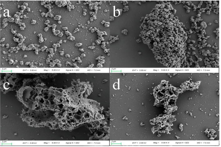
Figure 1.
SEM photograph of (a) untreated CaO, (b) CaO obtained at 900°C, (c) untreated CeO2/CaO, and (d) CeO2/CaO obtained at 900°C [
As demonstrated in Figure 1(b), when untreated CaO is compared to spent CaO at 900°C, untreated CaO has very small, more uniformly distributed particles. However, a major aggregation phenomenon is clearly observed in the spent sorbent following adsorption at temperatures below 900°C, resulting in sorbent sintering and a decrease in accessible active sites. In contrast, as demonstrated in Figure 1(d), CeO2/CaO did not change much before and after the reaction, implying that CeO2 doping increased its sintering resistance.
4.3 Fabrication of Al2O3/CaO with anti-sintering for efficient removal of As2O3
Due to its low cost and stable chemical properties, calcium oxide (CaO) has been extensively used as a high-temperature sorbent in the field of heavy metal removal. However, CaO tends to sinter at high temperatures, which degrades its adsorption performance. Using citric acid and calcine, a sintering-resistant Al2O3/CaO sorbent was synthesized, which was then applied in an innovative manner to the adsorption of As2O3 by combining experiment and theoretical analysis [46].
Based on the experimental findings, the potential internal mechanism of As2O3 adsorption on As2O3/CaO can be investigated further. CaO reacted with Al2O3 at a high temperature, producing Ca3As2O3, a support framework with high thermal resistance and a stable structure. Al2O3 can provide a large quantity of specific surface area and pore structure, which can facilitate the physical adsorption process, despite the fact that purified Al2O3 hardly reacts with As2O3. SEM can, therefore, reveal the unique surface morphology of As2O3/CaO. Al loses electrons in the presence of As2O3 to form Al3+, while CaO and As2O3 acquire electrons to form AlO4 tetrahedral structure by combining with Al3+. Population analysis and density of states reveal that Al becomes the principal active site of As2O3 adsorption and functions as the electron transport medium. In the meantime, the addition of Al can facilitate the separation of lattice oxygen, which may oxidize As2O3 and form a covalent bond on the adsorption surface. Therefore, Al2O3/CaO has a significantly greater absorption capacity than U-CaO.
4.4 Adsorption of arsenic by a-Fe2O3 adsorbent
The addition of an adsorbent to the combustion furnace can inhibit the volatilization of arsenic. Iron-based catalysts have been widely studied because they are widely available, inexpensive, harmless and have a large specific surface area. It is a technology that shows promise for removing arsenic from coal-fired flue gas. Among other things, iron-based adsorbents can remove elemental arsenic from flue gas by chemical reaction with arsenic or by physical adsorption; the surface lattice oxygen of Fe2O3 can oxidize As2O3(g) to As2O5(s) and form iron arsenate (FeAsO4) [49].
The results of the DFT study by Zhang et al. [50] also showed that As2O3 (g) could form eight stable adsorption structures on the (001) surface of Fe2O3 with a minimum adsorption energy of 275.52 kJ mol−1. One-step hydrothermal preparation was used by Zhao et al. [51] to create a tiny, spherical α-Fe2O3 adsorbent, and the effects of reaction temperature, nitric oxide (NO), oxygen (O2), nitric dioxide (NO), sulfur dioxide (SO2), and inlet arsenic concentration on the adsorption performance were investigated. The effect of its temperature on the capture of As2O3(g) by α-Fe2O3 is shown in Figure 2 [51].
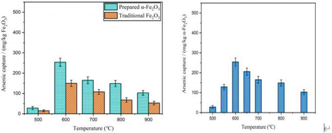
Figure 2.
(a) Arsenic capture by traditional Fe2O3 and the as-prepared α-Fe2O3 from 500 to 900°C. (b) Arsenic capture by α-Fe2O3 at temperatures from 500 to 900°C [
The experimental findings in Figure 2(a) demonstrated that the tiny spherical α-Fe2O3 had a higher adsorption capacity for As2O3 than conventional Fe2O3. According to Figure 2(b), temperature had a substantial impact on the adsorption capacity of α-Fe2O3. The adsorption capacity rose significantly when the temperature was raised from 500 to 600°C. However, the adsorption capability gradually declined after the temperature surpassed 600°C. Before and after the reaction, SEM of α-Fe2O3 was conducted; the findings are displayed in Figure 3 [51].
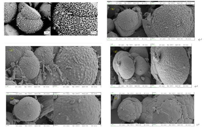
Figure 3.
SEM images of α-Fe2O3 before adsorption (a) and after adsorption at 500°C (b), 600°C (c), 700°C (d), 800°C (e), and 900°C (f) [
Pure α-Fe2O3 develops a tetragonal morphology with a regular distribution on the spherical surface, as shown in Figure 3(a), and it has an excellent spherical microstructure. Theoretically, compared to a smooth spherical surface, this form has more space for the physical adsorption of arsenic on the α-Fe2O3 surface due to its bigger specific surface area and adsorption active sites. The tetragonal angular morphology vanished and was replaced by a gradually smooth spherical shape when α-Fe2O3 absorbed arsenic in the experiment from 500 to 700°C (Figure 3(b–d)). This might be the outcome of the combined actions of calcination at high temperatures and arsenic adsorption. As the temperature increased from 800 to 900°C, it became more apparent that α-Fe2O3 was sintering and that there were less and fewer active sites available for adsorption (Figure 3(e, f)). Chemical adsorption was the key factor in the capture of arsenic.
In conclusion, the adsorption performance of α-Fe2O3 is temperature dependent. Due to the chemisorption mechanism, as the temperature rises from 500 to 600°C, its adsorption capability steadily increases. Its adsorption ability begins to decline as the temperature hits 600°C as a result of sintering. 600°C is the ideal adsorption temperature.
4.5 Catalytic adsorption of arsenic in the liquid phase
4.5.1 Preparation of CuO/TiO2 adsorbent
CuO/TiO2 adsorbent can be prepared by impregnation-thermal decomposition method. Weigh appropriate amount of Cu (NO3)2·3H2O and pour it into a beaker, add 20 mL of deionized water, and stir until Cu (NO3)2·3H2O is completely dissolved. 4.4 g anatase TiO2 was added, heated and stirred to get a uniform slurry, and then dried in a blast dryer at 80°C for 12 h to get a light blue solid. The samples were crushed and heated in a muffle oven at 5°C/min to 500°C and baked at this temperature for 4 h. TiO2 adsorbent with different CuO loads can be prepared successfully by taking out solids and grinding them carefully. Conditions to control the load: m (CuO): m (TiO2) = 0.00:1, 0.01:1, 0.10:1, and 0.20:1 (abbreviated as CT0, CT1, CT10, and CT20). For comparison, ordinary CuO without TiO2 is also obtained by calcination of Cu (NO3)2·3H2O.
4.5.2 Removal of arsenic in liquid phase by CuO/TiO2
Liquid-phase arsenic removal experiments are conducted in a laboratory-scale system. The appropriate amount of sodium arsenate solution was slowly poured into the adsorption reactor to ensure that the concentration of As(III) was 25 mg/L, and then the appropriate amount of adsorbent (CuO/TiO2, TiO2, and CuO) was added into the solution. Then, the magnetic agitator was started, and the adsorption was carried out dynamically at room temperature (25°C) at a rate of 300 r/min for 4 h. The constant temperature tank is connected to the adsorption reactor to ensure that the temperature will not interfere with the experimental results. At the end of the experiment, a syringe equipped with Millipore membrane filter (0.22 μm) was inserted into the extraction port to extract 4.0 mL of the reaction suspension. The filtered supernatant could be directly used in ICP-OES to determine the concentration of As in the supernatant without further treatment. The removal efficiency of arsenic at adsorption equilibrium is calculated as follows:
where
4.5.3 Effect of different CuO doping ratio on removal performance of arsenic in liquid phase
Different doping ratios of CuO have great influence on the crystallinity and morphology of CuO/TiO2 adsorbent and also affect the removal effect of CuO/TiO2 adsorbent on arsenic. Arsenic removal efficiency of CT0 (TiO2), CT1, CT10, CT20, and CuO samples after data processing is shown in Figure 4. CT0 is untreated anatase TiO2, and its removal efficiency for arsenic reaches 73.89%, indicating that pure TiO2 is indeed a material with good adsorption performance for arsenic. For CuO/TiO2 samples, the doping ratio of CuO is the key factor to determine the removal rate of arsenic. As can be seen from the figure, with the increase of CuO content, the removal efficiency of arsenic first increased and then decreased, and the highest removal efficiency of arsenic was CT10, with an efficiency of 83.17%. In the ascending stage of CT1 to CT10, with the increase of doping ratio, the removal effect of adsorbent on arsenic also increases. This is due to the doping of Cu element, which increases the original specific surface area of TiO2 and exposes more active sites. The reason why the removal efficiency of CT20 decreases is that with the continuous doping of CuO particles, the proportion of CuO increases, and the CuO is excessively attached to the surface of TiO2 crystal, occupying the effective active site on the surface of TiO2. In addition, the agglomeration of CT20 reduces the specific surface area of the adsorbent, resulting in the decrease of arsenic removal performance [52]. The removal efficiency of the CuO reference group was 3.61%, indicating that CuO alone has no affinity for arsenic and is difficult to be used as an adsorbent for arsenic removal alone. Therefore, appropriate proportion of CuO doping (CT10) can improve the adsorption performance of TiO2 for arsenic.
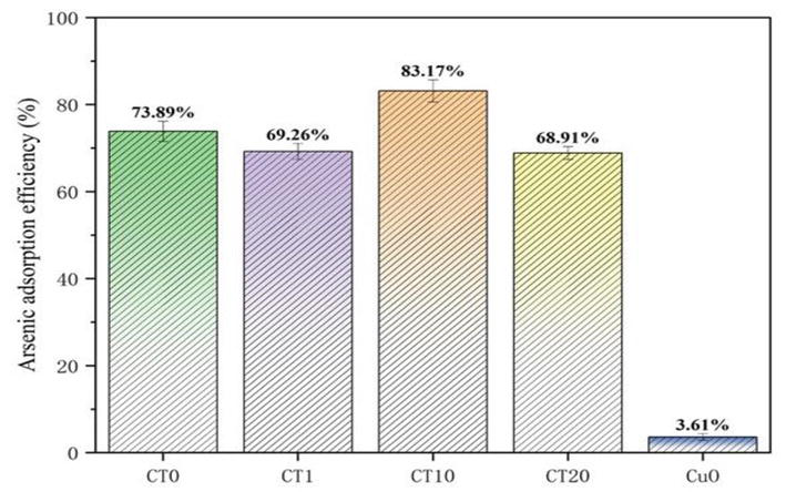
Figure 4.
Comparison of arsenic removal capacity of different doping ratios of CuO.
5. Theoretical study on arsenic adsorption
The composition of flue gas arsenic typically includes both elemental arsenic and various forms of oxidized arsenic, including AsO, AsO2, As2O3, and As2O5. The compound As2O3, which comprises trivalent arsenic (As3+), exhibits stable thermodynamic properties, presents a challenging dissociation process, and poses significant toxicity risks, thereby causing severe environmental and human health impacts. In addition, the presence of gaseous arsenic has the potential to impede the functionality of selective catalytic reduction (SCR) mechanisms, thereby inducing arsenic poisoning of SCR catalysts, which could ultimately diminish the financial advantages of power plants. Theoretical calculations are necessary to examine the mechanism of gaseous arsenic in fly ash, with the aim of comprehensively understanding the pattern of transformation and migration of flue gas arsenic to a particle state [53].
In recent years, density functional theory (DFT)-based quantum chemical computing has been increasingly utilized in pollution control research.
The research conducted in this study involved the development of an unburned carbon model for fly ash. Additionally, the researchers performed density functional theory (DFT) calculations to investigate the impact of surface defects, surface active chlorine groups, and an acidic gas atmosphere on the adsorption of elemental mercury. The theoretical findings were found to be consistent with the experimental results, leading to a comprehensive analysis of the aforementioned factors. This information is documented in Ref. [54]. A separate research endeavor was conducted to examine the impact of oxygen-containing functional groups (OCFGs) on the adsorption process of elemental mercury from unburned carbon in fly ash. The study revealed that OCFGs exhibited a notable ability to enhance the reactivity of neighboring carbon atoms. Furthermore, the quantity of carbon and hydrogen atoms present in the functional groups was found to have a substantial influence on the adsorption properties of mercury. In contrast, conventional density functional theory (DFT) calculations are typically performed assuming a temperature of absolute zero and an absolute vacuum. This poses challenges in establishing a direct correlation between the obtained results and the real-world operating conditions of power plants. Consequently, this can lead to distortions or even hinder the formation of conclusive findings [55]. Hence, the inclusion of the fundamental principles of thermodynamics becomes imperative in order to extrapolate the outcomes of density functional theory (DFT) calculations to a particular temperature range and effectively align with experimental or industrial circumstances. Nevertheless, there is a scarcity of research examining the dynamics of the interaction between gaseous arsenic and unburned carbon in fly ash. Additionally, a comprehensive investigation into the morphological characteristics of arsenic at different temperature intervals is lacking. In this section, the utilization of the DFT coupled thermodynamics method was employed to conduct a comprehensive investigation into the conditions necessary for the existence of flue gas arsenic, as well as the preferred structure it adopts, within the temperature range relevant to power plants. The adsorption behavior of various gaseous arsenic species was investigated. The objective of this study was to examine the structure of preferential adsorption and the key factors that influence the adsorption of arsenic on carbon-based carriers. The findings of this study are expected to contribute to the mitigation of arsenic pollution in coal-fired power plants [56, 57].
5.1 The theoretical model of arsenic adsorption
The theoretical framework relies on density functional theory (DFT) calculations, which are executed using the preexisting DMol 3 code programs [57]. The characterization of the system’s exchange-correlation functional was conducted using the Perdew-Burke-Ernzerhof (PBE) version of the generalized gradient approximation (GGA) functional [58]. The convergence tolerance was defined in the study as the maximum energy change of 2.0 × 10⁻⁵ Ha, the maximum force of 0.004 Ha/Å, and the maximum displacement of 0.005 Å [59]. The utilization of effective core potentials was employed in order to accurately describe the behavior of the core electrons. Additionally, the calculation was performed using the double numeric with polarization (DNP) basis set. The energy, population analysis, and density of states were subsequently calculated based on the geometrically optimized model. To evaluate the structural stability, the adsorption energy can be determined using the following formula.
where
To bring the results of DFT calculations closer to the actual conditions of an experiment or industrial application, thermodynamic methods must be used to extrapolate its conclusions. As one of the state parameters of a thermodynamic system, the Gibbs free energy can be used to determine the direction of a chemical reaction, as described below:
where
where
where
Finally, based on the ideal gas equation of state, the Gibbs free energy per unit mole of the system is obtained by (Eq. (8)).
where
where
5.2 Mechanism study of arsenic adsorption
The present study focuses on a comprehensive examination of the various potential forms of arsenic in flue gas, including As, AsO, AsO2, As2O3 and As2O5. The polar molecular structure of AsO2 arises from the positioning of two oxygen atoms on opposite sides of the arsenic atom. This configuration results in an As-O bond length of 1.664 Å and an O-As-O angle of 128.239 [60].
As illustrated in Figure 5, there are six distinct forms of gaseous As2O3 denoted as As2O3-x (where x ranges from 1 to 6). The As2O3-1 structure exhibits a notable superiority compared to the remaining six structures under conditions of low temperatures. However, with increasing temperature, the differentiation between As2O3-1 and As2O3-2 (or As2O3-4) gradually decreases. The stability of the As2O3-4 structures, exhibiting a chain-like arrangement, is observed to reach its maximum at a temperature of 900 Kelvin. The stability of As2O3-2, which bears a resemblance to a horn, is greater than that of As2O3-1 when exposed to temperatures exceeding 900 K [61, 62]. However, it is surpassed in stability only by As2O4-4. In earlier studies, it was widely accepted that the presence of As3+ in coal-fired flue gas predominantly manifested in a trigonal bipyramidal configuration, such as As2O-1, characterized by spatial symmetry and structural stability. At low temperatures, As2O3-1 is the dominant species. However, when the temperature surpasses 900 K, the likelihood of As2O3-2 and As2O3-4 being present becomes greater than that of As2O3-1. This observation implies that under elevated temperatures, the molecular bonds within the trigonal bipyramidal structure of As2O3-1, which are typically stable, will undergo dissociation, resulting in the formation of alternative structures (As2O3-2 and As2O4) that are not present under lower temperature conditions. Furthermore, the importance of the DFT combined thermodynamics approach in analyzing the morphology of arsenic in coal-fired flue gas under different operational temperatures is elucidated [63].
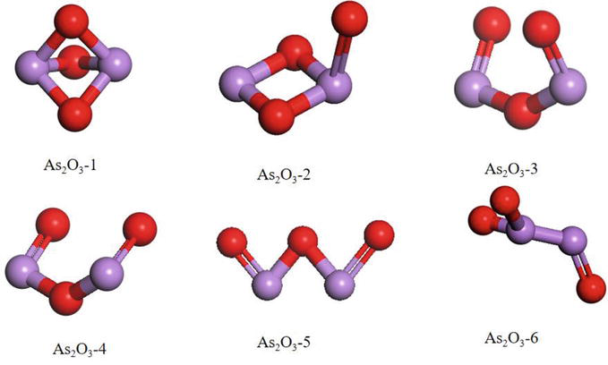
Figure 5.
Schematic diagram of the candidate As2O3 [
Next, the investigation focuses on the reciprocal conversion of oxidized arsenic, with particular emphasis on the As2O3 molecule as the reference point. The three equations, specifically Eq. (6.10), (6.11), and (6.12), are under consideration.
The reaction heat of the conversion of
6. Removal of arsenic from high-temperature flue gas by photocatalysis
The photocatalytic reduction happens when the incident light energy (hv) is not less than the band gap (Eg), and the electron (e−) in the valence band absorbs light energy and transitions to the conduction band, while the hole (h+) is generated in the valence band. The generated electron (e−) and the hole (h+) migrate to the semiconductor surface respectively under the action of electric field or diffusion. The electron (e−) with reducing ability and the hole (h+) with oxidizing ability have redox reactions with the substances adsorbed on the semiconductor surface such as pollutant degradation, water decomposition to produce hydrogen, etc. [64]. Thus, it can be known that when the band gap is smaller, the electrons in the valence band are more easily to transition to the conduction band, and the photocatalytic reduction reaction is more likely to occur.
6.1 Mechanism of photocatalytic oxidation reaction
The electronic characteristics of semiconductors are reflected through their valence band (VB) and conduction band (CB). Semiconductor VB is by the highest occupied molecular orbital (HOMO) the interaction of form, and CB is a minimum of molecular orbital (LUMO) interact with each other. There are no electronic states between the top of VB and the bottom of CB. The energy range between CB and VB is called forbidden bandgap (also called energy gap or bandgap) and is often expressed as Eg. The band structure, including the band and the positions of VB and CB, determines the light absorption properties and redox ability of semiconductors and is one of the important properties of semiconductor photocatalysts [65].
After the photocatalyst is irradiated by ultraviolet and/or visible light (Vis) from sunlight or illumination sources, the electrons in the valence band are excited to the conduction band, while the holes remain in the valence band. Thus, this creates negative electron (e−) and positive hole (h+) pairs [66]. T these photoinduced electrons (or holes) first need to resist the recombination induced by hole capture (or electron capture), and then migrate through the body and surface of the photocatalyst to reach the catalytic reaction site to catalyze water decomposition, CO2 reduction, and pollutant degradation [67]. n the photocatalysis process, e−/h+ pairs form in a few femtoseconds, their process from the original site to the reaction site takes only hundreds of picoseconds, and the catalytic reaction between e−/h+ and the adsorption reactants occurs in the time range of a few nanoseconds to a few microseconds [68]. The electron and hole recombination can last from a few picoseconds to tens of nanoseconds [69].
6.2 Photocatalytic removal of gaseous arsenic
Coal-fired power plants are the largest source of human arsenic pollution [54, 55, 70, 71], and effective control of various forms of arsenic emissions from coal-fired flue gas is critical to global arsenic pollution control. Arsenic in flue gas usually contains elemental arsenic and arsenic oxide such as AsO, AsO2, As2O3, and As2O5 [54, 55, 56, 57]. The As2O3-containing arsenic trivalent (As3+) has stable thermodynamic properties, is difficult to dissociate, is highly toxic, and is the most harmful to the environment and human health [56, 72]. In addition, gaseous arsenic can interfere with selective catalytic reduction (SCR) devices and lead to arsenic poisoning of SCR catalysts, thereby reducing the economic efficiency of power plants [73, 74].
As3+ exists in the flue gas in the form of compounds, among which the simplest form is As2O3. Based on DFT calculation, As2O3 with different initial configurations was geometrically optimized, and the final configurations were shown in Figure 6. As2O3, which is stable in the ground state, presents a spatially symmetric hexahedron structure. Each arsenic atom forms a single bond with three adjacent oxygen atoms and the As-O bond length is 1.96 Å. The strong bonding between arsenic and oxygen and the stability of molecular structure is not conducive to the transition of As3+ to higher valence state. The photocatalytic oxidation method is used to catalyze the oxidation of As3+ to a higher valence state. The possible reaction path is shown in Figure 7. The gaseous As3+ compound in the mainstream direction of the flue gas collides with the photocatalyst and has a certain probability of adsorption on the sample surface. The photocatalyst generates active groups such as hole (h+), hydroxyl radical ∙OH, and superoxide radical ∙O2−, which react with As3+ to oxidize it. Wu et al. developed Cu2+-doped BiOIO3 complex photocatalysts, rod-shaped Bi2S3 single-crystal adsorbents, In2S3/g-C3N4, CoS/g-C3N4, Bi4O5I2/g-C3N5, and other series of complex photocatalysts/adsorbents around the effects of graphite-phase carbon nitride loading on the specific surface area and active sites of photocatalysts, as well as on the formation of bismuth-based heterojunctions, the effects of different sulfur doping on photocatalysts, and the adsorption characteristics of mercury and arsenic by photocatalysts under light-free or light conditions. CoS/g-C3N4, Bi4O5I2/g-C3N5, and other series of complex photocatalysts/adsorbents. These adsorbents are characterized by increased specific surface area and smaller forbidden bandwidth, and it is pointed out that the adsorption characteristics of the photocatalysts for mercury, and arsenic are better in the presence of light conditions. The photocatalytic removal of arsenic from coal-fired flue gas is paved for the realization of photocatalytic removal.
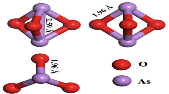
Figure 6.
Geometric optimization of gaseous arsenic As3+.
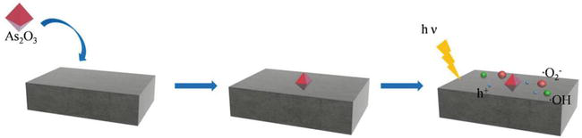
Figure 7.
Schematic diagram of photocatalytic oxidation of gaseous arsenic As3+.
7. Conclusion and outlook
Coal combustion in coal-fired power plants is one of the major anthropogenic sources of arsenic contamination in the environment. It has received increasing attention because of its high toxicity, volatility, and potential carcinogenicity. This chapter describes the nature and transport properties of arsenic in coal, as well as various arsenic removal techniques before, during, and after combustion. The main conclusions and outlook are as follows:
Arsenic can be divided into organic and inorganic arsenic, and there are two kinds of trivalent arsenic (As3+) and pentavalent arsenic (As5+), and the toxicity of As3+ is about 50 times that of As5+. Arsenic in coal mainly exists in three forms: pyrite, organic arsenic, and arsenate. In the process of coal devolatilization, exchangeable and organically bound arsenic evaporates easily, compared with arsenate, which is very stable and usually decomposes at relatively high temperatures.
Arsenic is mainly bound to fly ash in the flue gas during migration. In the high-temperature flue, as the temperature decreases, the silicate melts in the fly ash may dissolve the arsenic and encapsulate it in the fly ash. In addition, gaseous arsenic in the flue gas interacts with metallic elements such as calcium, aluminum, and iron in the fly ash to form arsenates. The arsenic enriched in fly ash migrates with the flue gas to the low-temperature flue and is removed by wet FGD units, ESPs and wet ESP units, and fixed in the waste such as FGD gypsum, fly ash, and wastewater. Although air pollution control equipment can remove the vast majority of arsenic, there is still some arsenic escaping into the atmosphere in gaseous form or attached to submicron particles, as well as the removed gaseous arsenic entering the FGD wastewater mainly in the form of PM as arsenic in the liquid phase, which is more complex and difficult to remove. Therefore, improving the dust removal equipment or developing a greener technology will be a direction for future research.
There are many different control technologies available. These technologies cover methods for removing arsenic from flue gas before to, during, and after burning. Precombustion control technologies mainly use coal beneficiation technology to make the arsenic content in raw coal lower. However, this technology has limitations and is only applicable to control arsenic escape in the form of inorganic minerals. The in-combustion control technology uses the addition of arsenic fixing agents or mixed coal combustion to convert arsenic from gaseous to granular form and from fine to coarse particles for subsequent removal treatment, thus improving the effectiveness of arsenic removal. Post-combustion control technologies reduce arsenic emissions by using existing air pollution control equipment and sorbents to fix and remove arsenic from the flue gas. One of the more mature flue gas arsenic removal processes today is sorbent-based arsenic removal. The adsorbent is used to convert As2O3 to arsenic-containing particulate matter or to oxidize low-soluble and highly toxic As2O3 to highly soluble and less toxic As2O5, which is then captured by air pollution control equipment.
In order to remove arsenic from flue gas more effectively, many researchers have modified the adsorbents to obtain better applicability for arsenic removal in complex flue gas environments. It has been shown that the adsorption of gas-phase arsenic on CaO and Fe2O3 is mainly chemisorbed at 600–900°C. The adsorption amount and efficiency decreased with increasing temperature. The three most effective adsorbents for arsenic are iron oxide, calcium oxide, and aluminum oxide. To solve the problem of adsorbent sintering at high temperatures, adsorbents, such as CeO2/CaO, and Al2O3/CaO, which are resistant to sintering, have been developed. At present, modification of adsorbents is a more effective way to improve the arsenic removal effect, and it can be an important direction to develop efficient arsenic adsorbents in future research.
The commonly used adsorbents for arsenic removal from coal-fired flue gas are relatively mature but have not yet been used in a wider range of applications and have high-cost problems. Therefore, there is an urgent need to develop new materials for the removal of arsenic. Photocatalysts have the advantages of mild reaction conditions, no secondary pollution, and strong redox properties. The application in arsenic removal from flue gas will be a great breakthrough.
Acknowledgments
This work was partially sponsored by the Nation Natural Science Foundation of China (52076126).
Conflict of interest
The authors declare that they have no known competing financial interests or personal relationships that could have appeared to influence the work reported in this paper.
References
- 1.
Xing H, Liu H, Zhang X, et al. In-furnace control of arsenic vapor emissions using kaolinite during low-rank coal combustion: Influence of gaseous sodium compounds. Environmental Science & Technology. 2019; 53 (20):12113-12120 - 2.
Guan Y, Liu Y, Lv Q, et al. Bismuth-based photocatalyst for photocatalytic oxidation of flue gas mercury removal: A review. Journal of Hazardous Materials. 2021; 418 :126280 - 3.
Jia T, Wu J, Song J, et al. In situ self-growing 3D hierarchical BiOBr/BiOIO3 Z-scheme heterojunction with rich oxygen vacancies and iodine ions as carriers transfer dual-channels for enhanced photocatalytic activity. Chemical Engineering Journal. 2020; 396 :125258 - 4.
Liu X, Gao Z, Wang C, et al. Hg0 oxidation and SO3, Pb0, PbO, PbCl2 and As2O3 adsorption by graphene-based bimetallic catalyst ((Fe, Co)@ N-GN): A DFT study. Applied Surface Science. 2019; 496 :143686 - 5.
Bunt JR, Waanders FB. Trace element behaviour in the Sasol–Lurgi MK IV FBDB gasifier. Part 1–the volatile elements: Hg, As, Se, Cd and Pb. Fuel. 2008; 87 (12):2374-2387 - 6.
Liu H, Wang C, Zou C, et al. Simultaneous volatilization characteristics of arsenic and sulfur during isothermal coal combustion. Fuel. 2017; 203 :152-161 - 7.
Yu S, Zhang C, Ma L, et al. Deep insight into the effect of NaCl/HCl/SO2/CO2 in simulated flue gas on gas-phase arsenic adsorption over mineral oxide sorbents. Journal of Hazardous Materials. 2021; 403 :123617 - 8.
Kang Y, Liu G, Chou CL, et al. Arsenic in Chinese coals: Distribution, modes of occurrence, and environmental effects. Science of the Total Environment. 2011; 412 :1-13 - 9.
Tian HZ, Lu L, Hao JM, Gao JJ, Cheng K, Liu KY, et al. A review of key hazardous trace elements in Chinese coals: Abundance, occurrence, behavior during coal combustion and their environmental impacts. Energy & Fuels. 2013; 27 (2):601-614 - 10.
Yudovich YE, Ketris MP. Arsenic in coal: A review. International Journal of Coal Geology. 2005; 61 (3-4):141-196 - 11.
Goodarzi F. Inorganic constituents of coal and their impact on coal quality. CIM Bulletin. 1994; 87 (983):47-56 - 12.
Guo R, Yang J, Liu Z. Thermal and chemical stabilities of arsenic in three Chinese coals. Fuel Processing Technology. 2004; 85 (8-10):903-912 - 13.
Li CX. Environmental protection measures for coal-fired power plants. Clean the World. 2019; 10 :38-39 (in Chinese) - 14.
Izquierdo M, Querol X. Leaching behaviour of elements from coal combustion fly ash: An overview. International Journal of Coal Geology. 2012; 94 :54-66 - 15.
Wang W, Qin Y, Song D, et al. Column leaching of coal and its combustion residues, Shizuishan, China. International Journal of Coal Geology. 2008; 75 (2):81-87 - 16.
Baba A, Gurdal G, Sengunalp F. Leaching characteristics of fly ash from fluidized bed combustion thermal power plant: Case study: Çan (Çanakkale-Turkey). Fuel Processing Technology. 2010; 91 (9):1073-1080 - 17.
Otero-Rey JR, Mato-Fernández MJ, Moreda-Piñeiro J, et al. Influence of several experimental parameters on As and Se leaching from coal fly ash samples. Analytica Chimica Acta. 2005; 531 (2):299-305 - 18.
Senior CL, Helble JJ, Sarofim AF. Emissions of mercury, trace elements, and fine particles from stationary combustion sources. Fuel Processing Technology. 2000; 65 :263-288 - 19.
Sun JM, Yao Q, Liu HY. Distribution and enrichment mechanism of arsenic in inhalable particulate matter from coal burning. Journal of Coal science. 2004; 29 (1):78-82 (in Chinese) - 20.
Contreras ML, Arostegui JM, Armesto L. Arsenic interactions during co-combustion processes based on thermodynamic equilibrium calculations. Fuel. 2009; 88 (3):539-546 - 21.
Chen D, Hu H, Xu Z, et al. Findings of proper temperatures for arsenic capture by CaO in the simulated flue gas with and without SO2. Chemical Engineering Journal. 2015; 267 :201-206 - 22.
Wang Y, Yu J, Wang Z, et al. A review on arsenic removal from coal combustion: Advances, challenges and opportunities. Chemical Engineering Journal. 2021; 414 :128785 - 23.
Song DY, Qing Y, Zhang JY, Wang WF. Washability characteristics of hazardous trace elements in coals from western region of China. Journal of China University of Mining and Technology. 2006; 35 :255-282 - 24.
Guo X, Zheng CG, Liu YH. Study on the speciation of mercury, arsenic and selenium in coal. Fuel. 2001; 22 :763-766 - 25.
Akers D, Dospoy R. Role of coal cleaning in control of air toxics. Fuel Processing Technology. 1994; 39 (1-3):73-86 - 26.
Wang WF, Qin Y, Song DY. Cleaning of potential hazardous elements during coal washing. Journal of Fuel Chemistry and Technology. 2003; 31 :295-299 - 27.
Zhou YP. Distribution type and occurrence form of arsenic in anthracite of laochang mining area. Coal Geology & Exploration. 1998; 26 :8-13 - 28.
Wang M, Song D, Zheng B, et al. The studying of washing of arsenic and sulfur from coals having different ranges of arsenic contents. Annals of the New York Academy of Sciences. 2008; 1140 (1):321-324 - 29.
Zhang Z, Fan J, Jin J, et al. Mode of occurrence of Pb, As, Be, Cr in coal. Ranliao Huaxue Xuebao (Journal of Fuel Chemistry and Technology);(China). 1992; 20 (2):206-212 - 30.
Gullett BK, Raghunathan K. Reduction of coal-based metal emissions by furnace sorbent injection. Energy & Fuels. 1994; 8 (5):1068-1076 - 31.
Zhao Y, Zhang J, Huang W, et al. Arsenic emission during combustion of high arsenic coals from southwestern Guizhou, China. Energy Conversion and Management. 2008; 49 (4):615-624 - 32.
Zhao B, Chen G, Qin L, et al. Effect of coal blending on arsenic and fine particles emission during coal combustion. Journal of Cleaner Production. 2021; 311 :127645 - 33.
Liu Huimin,Wang Chunbo,Zhang Yue,et al. Experimental and modeling study on the volatilization of arsenic during co-combustion of high arsenic lignite blends.Applied Thermal Engineering, 2016, 108: 1336-1343. - 34.
Marczak M, Wierońska F, Burmistrz P, et al. Investigation of subbituminous coal and lignite combustion processes in terms of mercury and arsenic removal. Fuel. 2019; 251 :572-579 - 35.
Wu D, Liu J, Yang Y, et al. Experimental and theoretical study of arsenic removal by porous carbon from MSW incineration flue gas. Fuel. 2022; 312 :123000 - 36.
Bartoňová L, Čech B, Ruppenthalová L, et al. Effect of unburned carbon content in fly ash on the retention of 12 elements out of coal-combustion flue gas. Journal of Environmental Sciences. 2012; 24 (9):1624-1629 - 37.
Díaz-Somoano M, Martínez-Tarazona MR. Retention of trace elements using fly ash in a coal gasification flue gas. Journal of Chemical Technology & Biotechnology: International Research in Process, Environmental & Clean Technology. 2002; 77 (3):396-402 - 38.
Li S, Gong H, Hu H, et al. Re-using of coal-fired fly ash for arsenic vapors in-situ retention before SCR catalyst: Experiments and mechanisms. Chemosphere. 2020; 254 :126700 - 39.
Yu S, Zhang C, Ma L, et al. Insight into As2O3 adsorption characteristics by mineral oxide sorbents: Experimental and DFT study. Chemical Engineering Journal. 2021; 420 :127593 - 40.
Córdoba P, Ochoa-Gonzalez R, Font O, et al. Partitioning of trace inorganic elements in a coal-fired power plant equipped with a wet flue gas desulphurisation system. Fuel. 2012; 92 (1):145-157 - 41.
Wang J, Zhang Y, Liu Z, et al. Effect of coordinated air pollution control devices in coal-fired power plants on arsenic emissions. Energy & Fuels. 2017; 31 (7):7309-7316 - 42.
López-Antón MA, Díaz-Somoano M, Spears DA, et al. Arsenic and selenium capture by fly ashes at low temperature. Environmental Science & Technology. 2006; 40 (12):3947-3951 - 43.
Diaz-Somoano M, Unterberger S, Hein KRG. Prediction of trace element volatility during co-combustion processes. Fuel. 2006; 85 (7-8):1087-1093 - 44.
Wang J, Zhang Y, Wang T, et al. Effect of modified fly ash injection on As, Se, and Pb emissions in coal-fired power plant. Chemical Engineering Journal. 2020; 380 :122561 - 45.
Zhang Y, Wang C, Li W, et al. Removal of gas-phase As2O3 by metal oxide adsorbents: Effects of experimental conditions and evaluation of adsorption mechanism. Energy & Fuels. 2015; 29 (10):6578-6585 - 46.
Hong J, Zhao Y, Wu J, et al. Fabrication of Al2O3/CaO with anti-sintering for efficient removal of As2O3 in simulated flue gas: Experimental and DFT study. Fuel. 2022; 307 :121812 - 47.
Zhao S, Xie X, Liao Y, et al. Removal of As2O3 in coal-fired flue gas by metal oxides: Effects of adsorption temperature and flue gas components. Journal of Cleaner Production. 2022; 376 :134239 - 48.
Li S, Zhang Z, Liu Q, et al. Preparation of CeO2/CaO with anti-sintering for efficient capture of As2O3 from flue gas at a high temperature. Energy & Fuels. 2021; 35 (24):20197-20205 - 49.
Zhang Y, Wang C, Liu H. Experiment and mechanism research on gas-phase As2O3 adsorption of Fe2O3/γ-Al2O3. Fuel. 2016; 181 :1034-1040 - 50.
Zhang Y, Liu J. Density functional theory study of arsenic adsorption on the Fe2O3 (001) surface. Energy & Fuels. 2019; 33 (2):1414-1421 - 51.
Zhao P, Guan J, Liu Q, et al. Microscopic spherical α-Fe2O3 for highly efficient gaseous arsenic capture in simulated flue gas under a wide temperature range. Energy & Fuels. 2021; 35 (23):19581-19591 - 52.
Ding W, Wan X, Zheng H, et al. Sulfite-assisted oxidation/adsorption coupled with a TiO2 supported CuO composite for rapid arsenic removal: Performance and mechanistic studies. Journal of Hazardous Materials. 2021; 413 :125449 - 53.
Ling Y, Li J, Zou C, et al. Interaction mechanism between gaseous arsenic and the unburned carbon in coal-fired fly ash: A DFT combined thermodynamics study. Chemical Engineering Journal. 2021; 425 :130714 - 54.
He KQ, Yuan CG, Jiang YH, et al. Synergistic effects of Fe-Mn binary oxide for gaseous arsenic removal in flue gas. Ecotoxicology and Environmental Safety. 2021; 207 :111491 - 55.
Tian C, Gupta R, Zhao Y, et al. Release behaviors of arsenic in fine particles generated from a typical high-arsenic coal at a high temperature. Energy & Fuels. 2016; 30 (8):6201-6209 - 56.
Shen F, Liu J, Zhang Z, et al. On-line analysis and kinetic behavior of arsenic release during coal combustion and pyrolysis. Environmental Science & Technology. 2015; 49 (22):13716-13723 - 57.
Winter RM, Mallepalli RR, Hellem KP, et al. Determination of As, Cd, Cr, and Pb species formed in a combustion environment. Combustion Science and Technology. 1994; 101 (1-6):45-58 - 58.
Perdew JP, Burke K, Ernzerhof M. Generalized gradient approximation made simple. Physical Review Letters. 1996; 77 (18):3865 - 59.
Ernzerhof M, Perdew JP. Generalized gradient approximation to the angle-and system-averaged exchange hole. The Journal of Chemical Physics. 1998; 109 (9):3313-3320 - 60.
Xu W, Zhang C, Shen H, et al. Surface oxalate coordination: Facilitating basic OER activity by regulating the electronic structure of Fe–Ni3S2. ACS Sustainable Chemistry & Engineering. 2022; 44 (10):14396-14406 - 61.
Zou C, Wang C, Chen L, et al. The effect of H2O on formation mechanism of arsenic oxide during arsenopyrite oxidation: Experimental and theoretical analysis. Chemical Engineering Journal. 2020; 392 :123648 - 62.
Ling C, Shi L, Ouyang Y, et al. Nanosheet supported single-metal atom bifunctional catalyst for overall water splitting. Nano Letters. 2017; 17 (8):5133-5139 - 63.
Gao Z, Zhao M, Yan G, et al. Identifying the active sites of carbonaceous surface for the adsorption of gaseous arsenic trioxide: A theoretical study. Chemical Engineering Journal. 2020; 402 :125800 - 64.
Chong MN, Jin B, Chow CWK, et al. Recent developments in photocatalytic water treatment technology: A review. Water Research. 2010; 44 (10):2997-3027 - 65.
Ma Y, Wang X, Jia Y, et al. Titanium dioxide-based nanomaterials for photocatalytic fuel generations. Chemical Reviews. 2014; 114 (19):9987-10043 - 66.
Bai S, Jiang J, Zhang Q, et al. Steering charge kinetics in photocatalysis: Intersection of materials syntheses, characterization techniques and theoretical simulations. Chemical Society Reviews. 2015; 44 (10):2893-2939 - 67.
Gopidas KR, Kamat PV. Photoinduced charge transfer processes in ultrasmall semiconductor clusters. Photophysical properties of CdS clusters in Nafion membrane. Journal of Chemical Sciences. 1993; 105 :505-512 - 68.
Zhang JZ. Interfacial charge carrier dynamics of colloidal semiconductor nanoparticles. The Journal of Physical Chemistry B. 2000; 104 (31):7239-7253 - 69.
Kubacka A, Fernandez-Garcia M, Colon G. Advanced nanoarchitectures for solar photocatalytic applications. Chemical Reviews. 2012; 112 (3):1555-1614 - 70.
Wang C, Liu H, Zhang Y, et al. Review of arsenic behavior during coal combustion: Volatilization, transformation, emission and removal technologies. Progress in Energy and Combustion Science. 2018; 68 :1-28 - 71.
Yang W, Gao Z, Liu X, et al. The adsorption characteristics of As2O3, Pb0, PbO and PbCl2 on single atom iron adsorbent with graphene-based substrates. Chemical Engineering Journal. 2019; 361 :304-313 - 72.
Liu H, Wang C, Zou C, et al. Vaporization model of arsenic during single-particle coal combustion: Numerical simulation. Fuel. 2021; 287 :119412 - 73.
Zhang H, Kong M, Cai Z, et al. Synergistic effect of arsenic and different potassium species on V2O5-WO3/TiO2 catalyst poisoning: Comparison of Cl−, SO42− and NO3− anions. Catalysis Communications. 2020; 144 :106069 - 74.
Lu Q, Pei X, Wu Y, et al. Deactivation mechanism of the commercial V2O5–MoO3/TiO2 selective catalytic reduction catalyst by arsenic poisoning in coal-fired power plants. Energy & Fuels. 2020; 34 (4):4865-4873