 Open access peer-reviewed chapter
Abstract
Fiber-reinforced plastics (FRP) offer great lightweight construction potential. However, the anisotropic high-performance materials can only be fully utilized through the development of material-specific joining processes. A literature study shows that conventional methods such as screwing, riveting and bolting are unsuitable, since the load-bearing fibers are severed in the joining region. This leads to high-stress concentrations. To reduce these, a method is presented in which through holes are created in thermoplastic FRP by reorienting the fibers in this area around the point of disruption in accordance with the load path. For this purpose, the polymer matrix is softened locally by applying heat and penetrated with a needle or mandrel. Based on this, a technology for material-specific joining of FRP and metals has been developed in the form of thermomechanical flow drill joining. In this process, a mandrel forms a bush from the metal component and deflects the fibers of the locally softened organic sheet to suit the material. Cold metal transfer (CMT) pin welding is presented as another fully automatable joining process. In this method, the softened plastic component is penetrated with the welding wire, displacing the fibers in the joining area and realigning them to suit the load path.
Keywords
- fiber-reinforced plastics
- thermomechanical flow drill joining
- cold metal transfer pin welding
- load path
- fiber orientation
1. Introduction
Lightweight design is an essential component in product development for reducing greenhouse gas emissions during component manufacture and especially during the use of moving components, thus making an important contribution to conserving resources and achieving climate targets. Fiber-reinforced plastics (FRP), especially carbon fiber-reinforced plastics (CFRP), provide great lightweight construction potential due to their high specific strengths and stiffnesses. For these reasons, the use of FRP is steadily increasing. The demand for carbon fibers (CF) has grown by nearly 60% from 58 kt in 2015 to 92 kt in 2021 [1].
In hybrid structural parts, concentrated loads are induced via the metal components. The CFRP components are used for load transfer. Thermoplastic FRPs can be integrated into existing process chains of metal constructions due to their reversible formability and thus have a significant advantage over thermoset systems. However, the lightweight potential can only be fully exploited by joining processes appropriate for the material.
The following strategies, for example, are pursued in the technological implementation of mixed designs with thermoplastic FRP and metals: Molding of the plastic onto the metal component in the molding process (IMA: In Mold Assembly) and direct bonding of the plastic to the metal component after the molding process (PMA: Post Molding Assembly); cf. e.g. [2, 3]. With the PMA technique, the metal and plastic components can be produced in separate manufacturing processes and subsequently joined by means of mechanical joining technology. The design of components in multi-material design has given significant impetus to joining technology, e.g. the combined riveting and adhesive bonding already used in car body construction, cf. e.g. [4]. In IMA processes, on the other hand, the joining elements are generally based on tight fit, e.g. by undercuts or holes in the metal component. Thus, the hybrid structure is produced simultaneously in the combined master molding and assembly process. The need for high-strength joints designed to withstand loads increases with the complexity of the components and the number of material groups used. In the design and manufacture of highly loaded lightweight structures in mixed construction with high-strength thin-walled metal and fiber composite components, PMA processes have major advantages over IMA techniques. This is mainly due to the significantly greater design freedom of PMA, which allows the structure to be designed according to the load path over a wide range [5].
Current joining methods, analyzed in a literature review, such as riveting and bolting require pre-hole cutting operations in which the load-bearing fibers are severed. Due to the high resulting notch stress concentrations, material thickening or heavy inserts are necessary, which is contrary to the lightweight concept. Following the literature study, this chapter describes thermomechanical flow drill joining (FDJ) and cold metal transfer (CMT) pin welding for joining thermoplastic FRP to metals. In these processes, the matrix is locally thermally softened in the joining zone and the fibers are displaced in the joining process and aligned to the load path. In this way, notch stresses are reduced and higher shear tensile strengths are achieved than with riveting, for example. In this way, even particularly high-performance continuous fiber-reinforced plastics can be joined appropriately for the material.
2. State of the art: joining technologies for FRP/metal hybrid structures
In the following, known methods for joining FRP and metals are summarized. For a detailed analysis of the different joining technologies see Ref. [5].
The integration of structural FRP components in the body shell by means of mechanical joining technology was successfully demonstrated e.g. in Ref. [6, 7, 8, 9, 10]. In addition to the various tests on basic components, the integration of large-area structural components, such as floor and bulkhead modules as well as high-performance ribs made of textile-reinforced plastics for space-frame design concepts, was one of the focal points of the investigations.
With regard to joining technology, methods that were originally developed for isotropic materials are often used for the FRP material group. A basic classification of these joining techniques can be made into detachable, partially detachable and non-detachable [4]. In this context, extensive studies and design information for mechanical connection systems [2, 7], adhesive connections [11, 12], welded connections [13, 14, 15, 16] as well as snap-fit [4, 17] and contour connections [11, 12] are sufficiently described in the literature. In addition, a distinction can also be made according to the principle of action between the firmly bonded (e.g. adhesive bonding, welding), the force-fit (e.g. clamping, pressing) and the form-fit connections (e.g. pins, contour connection) [18]. A further subdivision is made with respect to the geometric design of the joining zone into point and linear or planar joining systems.
2.1 Bolt connections
Bolt connections, which also include pin and rivet connections, are of particular importance for mixed construction with fiber composites and metals. Notes on the design are described in detail in Refs. [11, 18], for example. Bolt connections can be designed as single- or double-shear connections, overlapping and shafted, and with a lug on one or both sides [18]. At higher loads, the asymmetrical arrangement of the joining parts in the single-shear variant induces an eccentricity moment at the joint, which loads the joining partners for bending/peeling and leads to canting of the fastener. The associated failure can be counteracted by a symmetrical and thus double-shear arrangement of the parts to be joined. However, the increased component weight caused by the material doubling at the joint is a disadvantage.
The high potential of fiber-reinforced plastic composites cannot be fully exploited with rivets and bolts. Unlike metals, where stress concentrations at the holes are largely reduced by plastic flow processes, the installation of the fasteners (machining drilling, cutting component of self-piercing rivets) at the load application area leads to the severing of load-bearing fibers [19]. This causes high-stress concentrations at the hole edges, which often cause delamination and inter-fiber failures. The design and dimensioning of riveted and bolted joints in FRP is therefore fundamentally different compared to mono-metal designs, see e.g. [20, 21, 22]. In order to exploit the high material potential of fiber-plastic composites, the fiber arrangement in the load application area must be designed to withstand the stresses. The advantageous loop principle allows the introduction of particularly high loads [7].
2.2 Screw connections
Screw connections are widely used in mixed construction methods in general mechanical engineering and in vehicle construction. Unlike bolt connections, the introduction of loads at the connection point is predominantly perpendicular to the laminate plane. Classification can be made with respect to thread, head, and shank forms. In mixed designs with metals and FRP, a distinction is made between metal-side and plastic-side joining. An internal thread is produced on the plastic side using, for example, the tapping process [23] or thread-forming screws [24]. Alternatively, metallic thread inserts can also be integrated in the fiber composite [17]. For metal-side joining, flow drilling joining systems have proved particularly successful [25]. Metal- and plastic-side direct screwing processes as well as thread inserts are characterized by simple fabrication and one-sided accessibility of the joining point [26, 27].
2.2.1 Plastic side direct screwing
Various manufacturers offer thread-forming metal screws that can be inserted into structurally integrated core holes. The widely used direct screw process is used for inexpensively manufacturable unfilled as well as short- or long-fiber-reinforced injection-molded components and has been investigated, for example, in Refs. [2, 28, 29, 30]. The pull-out strength of plastic-set direct screw connections is determined, among other things, by the shear strength of the thread, with plastic threads exhibiting comparatively low values. The high degree of flexibility in the design of plastic components makes it possible to mold load introduction points in the injection molding process that are suitable for the load and serve to increase the screw-in depth [31]. In this way, screw-in tubes can be used to increase the pull-out strengths for thread-forming metal screws and reduce relaxation-related preload losses [29]. In the case of textile-reinforced plastic components, such load introductions can only be formed to a limited extent. For thin-walled thermoplastic FRP components in the high-performance range, direct screwing with thread-forming metal screws is, therefore, unsuitable.
2.2.2 Threaded inserts
Inserts are used in plastic components when requirements are placed on the connection point with regard to easy maintenance and interchangeability. Compared to the plastic-side direct screw connection systems, the thread insert merely transfers introduced assembly and operating loads from the screw to the surrounding plastic component. Threaded inserts are, on the one hand, embedded in-situ during the production of the molded part and, on the other hand, subsequently pressed in by ultrasonic or heating of the insert, screwed in or integrated by expanding the insert when driving in a screw in the FRP component [2]. In this process, the threaded inserts are mounted in screw-in tubes or directly in the component [24]. Inserts fulfill an integration-based adapter function between the plastic component and the metallic screw. A uniform distribution of the screw forces can be achieved as a result of special inserts with functional surfaces adapted to the material for force-locking, form-locking, or material-locking anchoring in the plastic component, cf. e.g. [32, 33, 34]. Threaded connections with inserts make an economic contribution to the implementation of connection systems suitable for large-scale production and are therefore used in many mixed construction systems with FRP components. For complex and highly stressed mixed construction systems, threaded inserts are not recommended—especially for thin-walled FRP components—because the connection forces are induced predominantly perpendicular to the direction of reinforcement. The transverse forces can thus only be applied locally with the connection system and thus cause interlaminar shear stress peaks at the joint, which often lead to premature failure of the FRP component.
2.2.3 Metal-side direct screwing with flow form screws
In addition to the plastic side, the assembly of a complex lightweight system in mixed construction can also be carried out using metal-side direct screw methods. In body-in-white construction, joining techniques using flow drilling screws have become particularly well established. These locally exploit the plastic flow properties of the metal component, such as the EJOT FDS® screw system, which offers significant advantages when joining chemically incompatible materials, see e.g. [35, 36]. Analogous to the plastic-side direct screwing, considerable transverse forces are generated at the joints of textile-reinforced thermoplastics during the production of FDS® joints. These induce a high-notch stress concentration due to the high screw-in torques during setting and the non-material-specific design of the screw head geometry, which leads to high interlaminar shear stress peaks [37]. For highly stressed mixed structures with thin-walled plastic components, direct bolting with flow-hole forming screws is therefore unsuitable.
2.3 Adhesive joints
Adhesive joints have been successfully used in vehicle construction for a long time and have proven their worth for mixed connections with metal and plastic components, see [38]. Adhesives are used in particular in the manufacture of front ends and add-on parts such as doors, tailgates, and engine hoods, e.g. [39]. An adhesive is a non-metallic material that joins parts by surface adhesion and internal strength (cohesion). Adhesive bonds can also be used to connect chemically incompatible materials, such as metals and plastics, in a quasi-substance-bonding manner. In this connection, the loads are introduced over a large area and almost homogeneously into the components of the mixed construction system. In contrast to bolted, riveted, and screwed joints, the fiber architecture on the composite component is not affected by the joining process, so that bonded joints for FRP components are generally considered to be particularly suitable for the material, see e.g. [40]. Adhesive bonding technology can be used to produce multifunctional joining systems which, in addition to force transmission, also perform sealing and vibration damping functions. In contrast, the high cost of pretreating the parts to be joined, such as activating the joining surfaces by means of radiation treatment, etching, grinding or degreasing with hydrocarbon compounds, to ensure reproducible joining properties—especially in large-scale production—is very cost-intensive [41].
2.4 Thermal contact joining
Thermal contact joining of short glass fiber-reinforced polyamide (GF20-PA6) and high-alloy austenitic steel X5CrNi18-10 (1.4301) is described in [42]. Prior to the joining process, pins are welded onto the metal component using modified gas metal arc welding (GMAW) technology. In contrast to conventional GMAW welding processes, the wire electrode consisting of the joining component material is not completely melted but is placed in a defined manner on a metal sheet so that the head geometry and length of the pins can be varied. The joining process is then carried out by pressing the overlappingly positioned joining parts. For this purpose, the FRP component is first plasticized up to the melting temperature of the matrix, followed by pressing the joining partners. Depending on the type and degree of mechanical surface activation, the plastic melt flows into the unevenness of the metal surface, resulting in form-fit and material-fit bonding mechanisms. The strength of the mixed joint is primarily determined by the pins of the metal component penetrating the FRP during the joining process.
2.5 Further joining methods for FRP
Further joining methods for FRP that are state of the art and/or the subject of current research work are summarized in the following.
Welding of metal/plastic-based mixed structures was investigated e.g. in Refs. [15, 16, 43, 44, 45, 46], where primarily ultrasonic and induction welding processes were considered. In this process, adhesion is based on the penetration of the polymer into the rough surface structure of the metal, the formation of dispersion forces and hydrogen bridge bonds, and the formation of weak covalent bonds between the metallic joining partner and the functional groups of the polymeric components. For the wetting of the joining partners, the specific surface and interfacial energies play a decisive role, which in this context is also referred to as thermodynamic adhesion [47]. Joining by ultrasonics of continuous fiber-reinforced organic sheets with metals was considered, for example, in Refs. [14, 48]. It was found that the metal component penetrates locally into the thermoplastic matrix of the composite component due to the ultrasonic vibrations acting perpendicularly to the joining zone, so that the metal component can enclose the exposed reinforcing fibers in the ductile state. Comparatively high-bond strengths are achieved by embracing the load-bearing fibers. In these investigations, mainly good formable metals such as Al99.5 were used. The induction welding process requires the electrical conductivity of the joined parts. Due to the induced resistance effects and the magnetic hysteresis during dissipation, heat is generated which leads to the plasticization of the thermoplastic matrix of the FRP component. The subsequent pressing allows the parts to be joined by a quasi-material bond, analogous to adhesive bonding, see [46, 47, 49].
No additional joining element is required for collar joining [3, 50, 51]. To produce the mixed joint, a hole is first drilled in the metal sheet. A collar is then formed from the metal sheet at this point with the aid of a die. In the process, a groove for the formation of an undercut on the collar of the metal sheet is created by the previous embossing with a matrix. In the actual joining process, the metal component with the collar is pressed into the plastic part, so that the undercut creates a form-fit connection between the joining partners. Collar joining is not recommended for continuously reinforced thermoplastic composite components because the reinforcing fibers are severed at the joint during pressing.
In the case of injection riveting, the connections are implemented using an injection molding technology adapted for this purpose [52]. Disadvantages of the technique, similar to stamp riveting [53], are the necessary two-sided accessibility as well as the complex plant and process technology.
2.6 Machining of FRP components
When drilling FRP, delamination and microcrack are often caused at the bore edges during the entry and exit of the drilling tools. The degree of damage is strongly influenced by the condition of the cutting blades, see [19]. At the exit point, the delamination is mostly caused by the abrupt penetration of the drill. In Refs. [54, 55, 56] it is recommended to support the FRP workpiece at the exit point by appropriate shims with softer materials, such as wood or aluminum plates, and to mount it with low vibration. In addition, the drilling process for thermoplastic fiber composites often leads to decomposition of the polymer matrix. To a limited extent, this process can be counteracted with cooled tools and reduced cutting and feed rates, see e.g. [57]. Damage to the bore edge can be largely avoided with circular or orbital milling processes [19]. To create a through hole, the drilling tool is fed along a helical path to the FRP workpiece. Thus, in contrast to conventional drilling technology, boreholes with different diameters can be produced with the aid of one tool. Furthermore, the axial machining forces and the associated tool wear are comparatively low if the cutting values are selected appropriately. The production of internal threads is described in Refs. [19, 23, 58] for glass fiber-reinforced plastic (GFRP) and CFRP components. Internal threads can be produced in FRP components by tapping, cutting, milling and thread forming. In thread forming, the thread flanks are shaped by a forming process. For this purpose, the forming studs of the thread forming tool are pressed into the pre-drilled workpiece, whereby the thread flanks are formed due to plastic deformation. In contrast, drilling and milling processes represent material-removing machining techniques. In tapping, the thread flanks and thread tips are already significantly damaged when the core hole is inserted at the base of the thread. The resulting spalling, fiber bundle fractures and kinks as well as distortions often considerably reduce the strength behavior of the screwed connection. Thread milling, on the other hand, causes much less damage with comparatively low machining forces.
3. Design of through holes suitable for FRP
The load-bearing fibers of the highly anisotropic FRP must be oriented around through-holes in accordance with the load path in order to utilize the full material potential. The analysis of construction principles in nature and their adaptation to disturbance points provides guidance in optimizing the shape of these areas. For example, in trees, the maintenance of a constant stress distribution at the disturbance zone is observed, see e.g. [59, 60]. If a tree is damaged, e.g. by cracks, decay or fractures, the resulting stress increases are reduced or absorbed by the accumulation of additional or firmer material near the defect [61, 62] (Figure 1a).
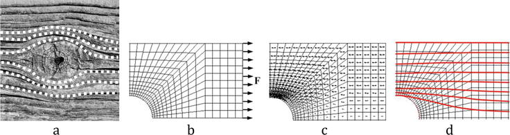
Figure 1.
(a) Fiber orientation around a knothole, (b) numerical model, (c) principal stress trajectories, (d) optimized fiber orientation [
Since wood has maximum strength and stiffness properties only in the direction of the fibers, the tree always strives to align its wood fibers along the highest stress, see for example [63]. The orientations of the wood fibers thereby largely correspond to the direction of the greatest principal stress, reducing the shear between the fibers and increasing the material utilization. This design principle of nature can be used in technical FRP applications to increase strength, especially at notch-sensitive component sections (e.g., at holes or cutouts), as a design model for the load-appropriate arrangement of reinforcing fibers at load application areas. Based on this principle, optimization algorithms have been developed in Refs. [64, 65] to align the fibers in the direction of the principal stress trajectories in a load-appropriate manner (Figure 1b–d). The methods presume freedom from shear stresses in the principal stress system. Since the fiber composite component has the largest modulus of elasticity in the longitudinal direction of the fibers, the FRP component is stiffness-optimized by the specific arrangement of the reinforcing fibers in the principal stress direction.
In contrast to thermoset FRP, where the redirection of the fibers at the load application points must already be taken into account in the preform process (Figure 2a), the reorientation of the reinforcing fibers in textile-reinforced thermoplastics can be carried out subsequently on the component, see e.g. [66, 67, 68, 69, 70]. To ensure radial displacement of the fibers within the matrix (Figure 2b), a defined area must first be plasticized at the load introduction area of the organic sheets. The viscosity of the matrix can be reduced in a targeted manner by local heat input, so that the reinforcing fibers can be reoriented in the forming zone, for example with the aid of a needle [5].
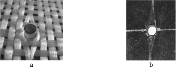
Figure 2.
Reorientation of the fibers (a) of a textile fabric around an insert prior to the resin insertion and (b) in a thermoplastic FRP [
Due to the local heating, however, the fibers remain firmly clamped in the adjacent colder matrix material and are therefore stretched differently during reorientation with the needle tool. Thus, in addition to the diameter of the through hole, the permissible strain at break of the fiber component in particular must be given special consideration when dimensioning the reforming area. In the following model (Figure 3), the most deflected and most elongated fibers of a unidirectional single layer at the needle edge are considered [5].
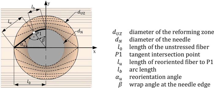
Figure 3.
Schematic representation of fiber redirection on a unidirectional prepreg layer [
Since the diameter
The filaments located directly at the bore edges are prestressed in the range of failure strain. To ensure that further loading does not lead to fiber breaks, the heating region must be selected larger than the diameter
In Ref. [5], a test rig was developed and implemented. The results were validated in bolt tensile tests following DIN 65562. Reference specimens were produced with spiral and wood drills. Especially with the spiral drill, delamination is caused at the bore edges. The test results of Ref. [5] show that the utilization of the high specific strength and stiffness properties of organic sheets can be increased by more than 28% by designing the load application point to suit the load. In addition, the deformation work of the specimens with the hot-formed holes is 25% higher than that of the reference specimens.
Different failure mechanisms can be observed in the breakage images and fracture patterns of the tested components. Whereas machined specimens fail primarily by strong delamination, cracks and intermediate fiber fractures at the edge of the hole, the test specimens with formed holes only show fiber fractures at the 90° layers arranged transverse to the loading direction [5].
In contrast to the spiral-drilled specimens, the strength
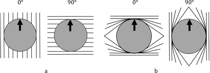
Figure 4.
Loading of the 0° and 90° layers in orthogonal multilayer composites with (a) machined holes and (b) hot-formed holes [
4. Thermomechanical flow drill joining
In Ref. [5], comprehensive investigations were carried out on the manufacturing of metallic bushings by means of the flow drilling process as well as on their quality evaluation. This process uses a rotating hard metal mandrel which penetrates into the metal component (Figure 5). As a result of the frictional heat generated, the resistance of the base material is reduced to such an extent that the drill mandrel can be pushed through the metal component with little force. As soon as the metal plasticizes at the entry point of the working area, it initially begins to flow at the taper in the opposite direction to the feed direction. At the same time, as the sheet is pushed through, the material is dragged along in the feed direction as a result of combined friction/flow processes, causing a bushing to form on the underside.
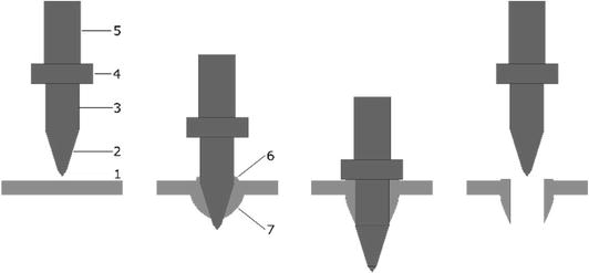
Figure 5.
Flow drilling method with 1 working area, 2 cone, 3 cylindrical area, 4 collar, 5 shank, 6 material flow against feed direction, 7 bush, according to ref. [
Based on this technology, thermomechanical flow drill joining for hybrid components made of FRP and metal, which is also suitable for economical large-scale production, was developed. The process is characterized by short process times, force-flow-compatible and high-strength joining properties, and a high degree of lightweight design. In contrast to many common processes, no auxiliary joining element is required. To produce a FDJ joint, the plastic flow properties of the metal component are specifically used. A rotating mandrel is used to thermomechanically form a bush from the metallic base material as described above. The heat generated causes the thermoplastic to plasticize. Alternatively, further heat can be introduced by heating elements. During the forming process, the bush is pushed directly through the thermoplastic FRP component (Figure 6a), which is also plasticized locally and then turned over positively when the mandrel is reset or in a further process step (Figure 6b). The fibers are reoriented around the flat joints (Figure 6c and d).
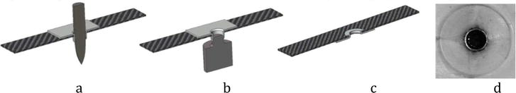
Figure 6.
Principle for manufacturing a FDJ connection [
In Ref. [5], a joining device was developed, designed and implemented. It provides the industry with an efficient technology for the production of material-specific joints between FRP and metals using FDJ technology. In a comprehensive parameter study, the optimal process variables for joining FRP of different thicknesses and different metal alloys were determined. The comparison of the head and shear tensile strengths based on DIN EN ISO 14272 and DIN EN ISO 14273 of the new joining technology with conventional methods such as riveting and flow-forming screws shows a significantly higher load-bearing capacity of the FDJ joints (Figure 7). The process parameters with which the specimens for the tests in Figure 7 were produced are given in Ref. [5] page 79 Figures 7–13.
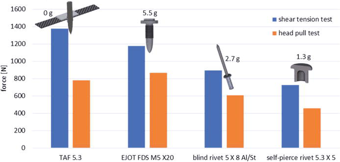
Figure 7.
Comparison of head and shear tensile strength of FDJ joints with conventional joining methods [
With the developed failure hypothesis for the sizing of the joints with the FEM, the method also meets the requirements of the industry for the calculation and dimensioning of the joined components [5].
5. CMT-pin technique
The FDJ technology can be used to create highly stressable material-compatible joints between thermoplastic FRP and metals. However, many applications, e.g. in automotive engineering, require a closed joint, which is not provided by the FDJ process due to the remaining through-hole.
Therefore, joining of FRP with metals by cold metal transfer pin welding (CMT pin) is proposed as an alternative automatable process with one-sided accessibility. For improved low-spatter droplet separation with minimal heat input compared to MIG and MAG welding, this arc welding process uses computer controlled backward movement of the wire during short-circuiting, followed by movement toward the workpiece. The technology was developed by the company Fronius International GmbH and can be adapted for welding pins. Fronius provides appropriate operating curves for this purpose.
Sequential joining, in which the pins are first welded and then the polymer component is pressed on or, in the case of duroplastic systems, cast on, is well known. In the process described below, the FRP component is joined in situ.
In the first process step, the FRP is positioned over the metal and heated, e.g. by means of an infrared radiator, until the thermoplastic matrix softens (Figure 8a). Subsequently, the welding wire is pushed through the organic sheet by feeding the wire or a movement of the robot and the fibers are displaced according to the load path (Figure 8b). The use of an endless welding wire as joining element (pin) ensures flexible pin lengths even on graded wall thicknesses of the FRP. Immediately after contacting the wire, it is welded to the metal. The so-called pin foot is formed, the shape of which can be optimized by moving the wire forwards or backwards. Finally, the wire is separated by a separation pulse (Figure 8c). The head shape of the pin can be adjusted by selective adaptation of the process parameters. The connection is form-fit. The pin shaft takes up the forces in the plane and the head orthogonally to it.
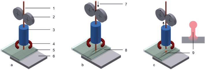
Figure 8.
Process steps in CMT pin joining of FRP and metals [
In Refs. [72, 73], a heating strategy using infrared radiation was developed. The heating of flat sheets of carbon fiber-reinforced polyamide 6 (CF-PA6) with infrared radiation was modeled using the finite element method (FEM), allowing the temperature distribution in the sample to be studied in greater detail than is possible experimentally. The infrared radiation heats the upper surface of the CFRP sheet. Some of this heat is released back into the environment by convection and by radiation. In the plate, heat transport takes place by means of conduction. Due to the time dependence of the heating process, the heat capacity and density of the material are needed in the simulation. The emission coefficient describes the heat transfer by radiation and the heat transfer coefficient describes the convective heat transfer. Both values were determined in a parameter study. For this purpose, the values are varied systematically and the FEM calculations are performed in each case. The temperatures as a function of time were compared with the experimental data at several points along the plate diagonals. The density of the PA6-CF is 1.434 g/cm3. Heat capacity (Figure 9) was measured using differential scanning calorimetry technique with a heating rate of 10 K/min. The thermal conductivity calculated according to Refs. [11, 74, 75, 76] is 4.72 W/(m∙K) in the fiber direction and 0.48 W/(m∙K) perpendicularly.
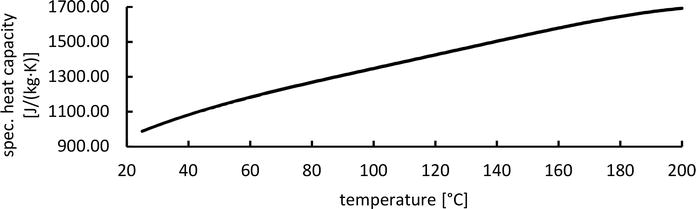
Figure 9.
Experimentally determined temperature-dependent heat capacity of the CFRP investigated [
A layup with a sequence of 0 and 90° plies was investigated. The plate thicknesses considered are 2 and 3.8 mm. The calculations were performed with the software Abaqus 2019. To validate the FEM models, the heating of square CFRP sheets with an edge length of 150 mm at different distances of the IR radiator to the CFRP surface was studied experimentally. To observe the area distribution of the temperature on the irradiated side, 16 thermocouples were pressed into the CFRP sheet along the diagonals at different distances from the center of the sheet. The 250 W Omega radiator is assumed to be a circular radiator in Refs. [72, 73] and the model is built with a cyclic symmetry. Since losses are assumed, the radiator power is assumed to be 210 W in the model. The smallest deviation between experiment and FEM was obtained with a constant heat transfer coefficient of 2.5 W/(m2∙K) and an emission coefficient for the CFRP of 0.95 and for the radiator of 0.6 (Figure 10).
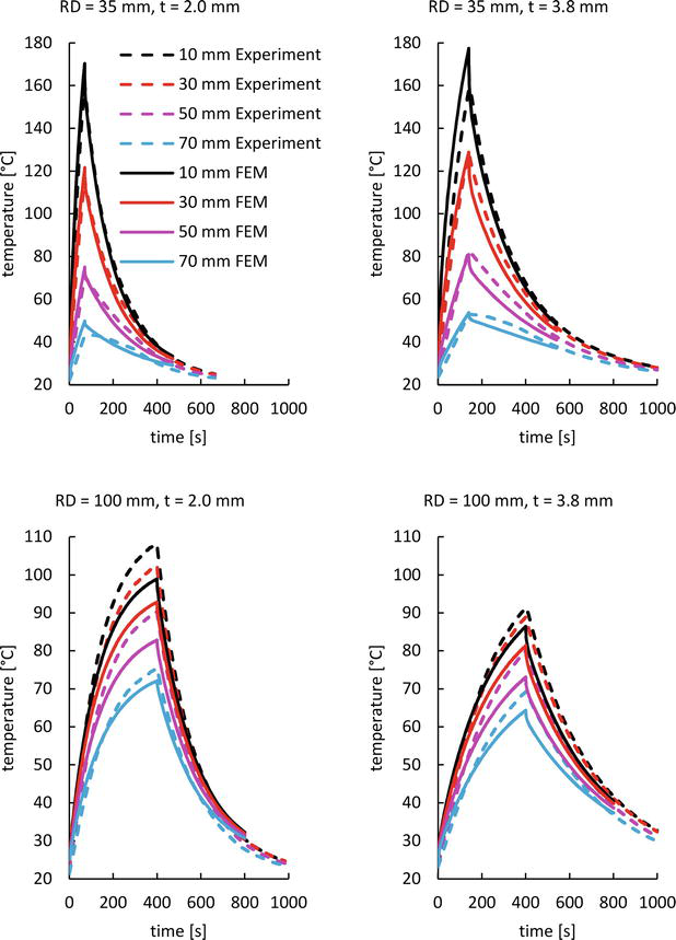
Figure 10.
Comparison of the temperature curves on the top surface between experiment and 3D simulation for different distances of the measuring points to the center of the plate along the diagonal [
The comparison of the temperature fields recorded in the experiment with a thermal imaging camera with the simulation results also indicates a high level of agreement.
With the help of the models built in this way, it was possible to analyze different radiators and process cycles in Refs. [72, 77] and thus develop a heating strategy suitable for CMT pin joining.
On this basis, comprehensive parameter studies were carried out in Refs. [72, 77] on the joining of CF-PA6 with sheets of 1.5528 with a 150 g/m2 Al-Si coating. It was found that the electrically conductive CFRP cannot be joined by this method. The welding wire penetrates the CFRP, but moves back to the surface of the organic sheet to ignite the arc. When the arc is ignited, the CFRP is severely damaged due to the strong and rapid heat input. Since the process curves are pre-programmed by the manufacturer, it was not possible to develop a welding strategy in Ref. [72] in which the arc ignites on the metal. Therefore, the joining of dielectric glass fiber-reinforced polyamide 6 (GF-PA6) was investigated as an alternative. With this material, the arc ignites on the steel sheet as intended. Even with a distance of 1.5 mm between the steel and the GFRP, some of the fibers are not completely diverted around the pin but are pushed out downwards, so that they disrupt the welding process. The reason for this is that with the corresponding welding parameters, not only the pins have spherical heads, but also the welding wire. In a further parameter study, a two-stage process sequence was developed in which the heated and thus softened organic sheet is first penetrated by the robot movement with a pointed welding wire, so that all joints are pre-holed according to the material and then the pins with spherical heads are welded. By means of microcomputer tomographic analyses, the deflection of the fibers around the pin could be demonstrated (Figure 11). Micrographs of the weld metal show complete bonding of the pin foot to the base material (Figure 12).
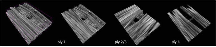
Figure 11.
Microcomputer tomographic analysis of GFRP sheet after penetration [
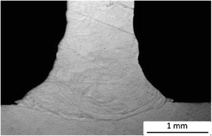
Figure 12.
Micrograph of pin foot [
Using the process described, in which the locally preheated organic sheet is first penetrated at the joints with a pointed welding rod and then the pins are welded, it was possible to implement functional demonstrators in Refs. [72, 77] as GFRP sheets welded onto steel-hat profiles. This represents thrust fields, e.g. in vehicle construction. A comparison with glued specimens was made in a three-point bending test. An 8% higher flexural strength and an approx. 25% greater work of fracture of the CMT pin joined specimens can be determined [72, 77].
For detailed analyses of this joining method and validation in experimental tests, see Refs. [72, 73, 77].
6. Conclusion and outlook
It has been shown that conventional methods such as screwing, riveting, and bolting are unsuitable, especially for joining continuous fiber-reinforced FRP with metals, since the load-bearing fibers are cut during the pre-hole cutting operations or when the joining elements are set. This leads to considerable notch stress concentrations at the joints. To reduce these, a method based on nature’s construction methods was presented in which through-holes are created in thermoplastic FRP by reorienting the fibers in this area to match the load path around the point of disruption. To do this, the polymer matrix is softened locally by applying heat and penetrated with a needle or mandrel. Based on the strain at break of the fibers, the diameter of the forming area is calculated.
Based on these results, flow hole forming was used as a starting point for the development of a joining technology for connecting FRP and metals in a way that is suitable for the material: thermomechanical flow drill joining. In this process, a mandrel forms a bush from the metal component. The heat generated in the process softens the plastic of the organic sheet so that the fibers are displaced instead of severed. Another joining process that can be fully automated is CMT pin welding. In this process, the matrix is also softened by the application of heat, e.g. by infrared radiation. The plastic component is then penetrated with the welding wire, displacing the fibers in the joining area and realigning them to suit the load path. A separation pulse is finally used to form a head, thus securing the organic sheet against lifting from the metal component. The advantage of the CMT pin technique over the FDJ process is that the joints are closed, but they are not flat due to the pin heads. Furthermore, CMT pin welding can currently not be used to join electrically conductive CFRP with the manufacturer’s predefined process curves.
As an alternative to these two technologies, the research group Sustainable Lightweight Technologies ZenaLeb of the Fraunhofer Institute for Applied Polymer Research IAP Division Polymeric Materials and Composites PYCO and the Chair of Polymer-based Lightweight Design of the Brandenburg University of Technology Cottbus-Senftenberg in Germany is currently analyzing the capability of a new method based on stud welding [78]. In this process, the FRP is pre-heated (Figure 13a) analogously to the CMT pin technique. It is then penetrated by a joining element, a stud in the form of a nail, so that the fibers are reoriented according to the load path (Figure 13b). Due to the adjustable stud geometry with a flat head, in contrast to the CMT pin technique, plane joints (Figure 13c) can even be realized with CFRP, which, in contrast to the FDJ process, are closed.

Figure 13.
Stud welding process for joining thermoplastic FRP and metals. 1 stud welding gun, 2 heater, 3 stud, 4 FRP, 5 steel part, 6 reoriented fibers, 7 stud joint.
Acknowledgments
The results presented in this chapter were generated in several research projects funded by the Federal Ministry for Economic Affairs and Climate Action and the Federal Ministry of Education and Research.
References
- 1.
Sauer M, Schüppel D. Composites Market Report 2021 - the Global Market for Carbon Fibers and Carbon Composites. Freely Accessible Short Version. Berlin: Composites United e.V; 2022 - 2.
Ehrenstein GW. Handbuch Kunststoff-Verbindungstechnik. München: Hanser Verlag; 2004 - 3.
Endemann U, Glaser S, Völker M. Verbindungstechnik für Kunststoff-Metall-Hybridstrukturen: Kunststoff und Metall im festen Verbund. Ludwigshafen, Germany: Kunststoffe; 2002. pp. 110-113 - 4.
Neitzel M, Mitschang P, Breuer U. Handbuch Verbundwerkstoffe - Werkstoffe, Verarbeitung, Anwendung. 2nd ed. München: Hanser Verlag; 2014 - 5.
Seidlitz H. Entwicklung von kraftflussgerechten Verbindungstechniken für Mischbauweisen mit thermoplastischen Faserverbunden und Metallen. In: Dissertation. Chemnitz: Technischen Universität Chemnitz, Fakultät für Maschinenbau; 2013 - 6.
Ruther M, Jost R, Freitag V, Peitz V, Piccolo S, Brüdgam S, et al. Fügesystemoptimierung zur Herstellung von Mischbauweisen aus Kombinationen der Werkstoffe Stahl, Aluminium, Magnesium und Kunststoff. Final Report. Paderborn: Universität Paderborn, Werkstoff- und Fügetechnik; 2003 - 7.
Hahn O, Bye B, Draht T, Lübbers R, Ruther M, Zilg C, et al. Fügen von faserverstärkten Kunststoffen im strukturellen Leichtbau. Paderborn: Universität Paderborn; 2004 - 8.
Lesemann M, Sahr C, Hart S, Taylor R. SuperLIGHT-CAR - the multi material car body. In: 7. LS-DYNA Anwenderforum. Bamberg: RWTH Aachen University, Institut für Kraftfahrzeuge; 2008 - 9.
Steinig M. Hochgeschwindigkeitsbolzensetzen für hochfeste und hybride Strukturverbindungen. Tagungsband T32 des 31. EFB-Kolloquiums Blechverarbeitung. Bad Boll: EFB: Hochfeste und hybride Materialien - Schnelle Umform- und Fügeverfahren; 2011 - 10.
Schöll R, Friedrich HE, Erdl G. Innovative Fahrzeugleichtbaustruktur in Spant- und Space-Frame-Bauweise. Zeitschrift für Produktentwicklung und Ingenieur-Werkstoffe. 2009:37-38 - 11.
Schürmann H. Konstruieren mit Faser-Kunststoff-Verbunden Berlin. Heidelberg: Springer-Verlag; 2007 - 12.
Moser K. Faser-Kunststoff-Verbund: Entwurfs- und Berechnungsgrundlagen. Düsseldorf: VDI-Verlag; 1992 - 13.
Krüger S, Wagner G, Eifler D. In: Degischer HP, editor. Eignung des Metall-Ultraschallschweißen zum Fügen von Verbundwerkstoffen. Weinheim: WILEY-VCH; 2003 - 14.
Ageorges C, Ye L, Hou M. Advances in fusion bonding techniques for joining thermoplastic matrix composites: A review. Composites Part A: Applied Science and Manufacturing. 2001; 32 (6):839-857 - 15.
Balle F, Huxhold S, Emrich S, Wagner G, Kopnarski M, Eifler D. Influence of heat treatments on the mechanical properties of ultrasonic welded AA 2024/CF-PA66-joints. Advanced Engineering Materials. 2013; 15 :837-845 - 16.
Balle F, Wagner G, Eifler D. Ultrasonic metal welding of aluminium sheets to carbon fibre reinforced thermoplastic composites. Advanced Engineering Materials. 2009; 8 :35-39 - 17.
Ehrenstein GW. Mit Kunststoffen konstruieren. Universität Erlangen-Nürnberg. München: Hanser-Verlag; 2020 - 18.
Bergmann HW. Konstruktionsgrundlagen für Faserverbundbauteile Berlin. Heidelberg: Springer-Verlag; 1992 - 19.
Weinert K. Bearbeitung von Textilverbunden. In: Hufenbach W, editor. Textile Verbundbauweisen und Fertigungstechnologien für Leichtbaustrukturen des Maschinen- und Fahrzeugbaus. Dresden: SDV-Die Medien AG; 2007. pp. 90-99 - 20.
Niklewicz J, Ferris DH, Nunn GJ, Sims GD. The use of pin bearing data for the preliminary design of ‘bolted’ joints. In: International Conference on Joining and Repair of Plastics and Composites. London: Woolstencroft, D. H.; 1999. pp. 13-22 - 21.
Hufenbach W, Gude M, Freund A. Simulation des Schädigungsverhaltens von thermomechanisch beanspruchten Blindnietverbindungen in CFK/Al-Strukturen. NAFEMS Magazin. 2008;(10):30 - 22.
Kroll L, Mueller S, Mauermann R, Gruetzner R. Strength of self-piercing rivited joints for CFRP/aluminium sheets. In: 18th International Conference on Composite Materials (ICCM18). Jeju Island, Korea; 2011 - 23.
Weiner K, Kempmann C. Gewindefertigung in faserverstärkten Kunststoffen. Kunststoffe. 2004; 7 :44-48 - 24.
Renz R, Ahlers-Hestermann G, Humm H. Mechanisches Fügen von Kunststoffen - Direktverschraubung von Formteilen aus Kunststoffen und Gewindeeinsätze Teil 1. Joining Plastics. 2008; 2 (1):64-69 - 25.
Küting J, Hahn O. Entwicklung des Fliessformschraubens ohne Vorlochen für Leichtbauwerkstoffe im Fahrzeugbau. In: Dissertation. Paderborn: Universität Paderborn, Laboratorium für Werkstoff- und Fügetechnik; 2004 - 26.
Tome A, Dratschmidt F, Ehrenstein GW. Direktverschraubungen in Kunststoff - Günstig auf lange Sicht? Plastverarbeiter. 1998; 49 :124-127 - 27.
Küting J, Meschut G. Direktverschrauben ohne Vorlochen zur Realisierung einseitig zugänglicher Verbindungen im Karosseriebau. Blech Rohre Profile. 2003; 2 :33 - 28.
Dratschmidt F. Zur Verbindungstechnik von glasfaserverstärktem Polyamid - Schrauben und Inserts. In: Dissertation. Erlangen: Universität Erlangen-Nürnberg, Lehrst. f. Kunststofftechn; 1999 - 29.
Tome A. Vorspannkraftrelaxation von Kunststoff-Direktverschraubungen. In: Dissertation. Erlangen: Universität Erlangen-Nürnberg, Lehrst. f. Kunststofftechn; 2000 - 30.
Pyper M. Kunststoffteile direkt verschraubt. Konstruktion & Engineering. 2006; 9 :80-81 - 31.
Renz R, Ahlers-Hestermann G, Humm H. Mechanisches Fügen von Kunststoffen - Direktverschraubung von Formteilen aus Kunststoffen und Gewindeeinsätze Teil 2. Joining Plastics. 2008; 2 (2):142-148 - 32.
Kerb-Konus-Vertriebs-GmbH. Gewindeeinsätze für Kunststoffe und Holz: Produktdatenblatt Nr. 30. 2012. Available from: http://www.kerbkonus.de/ [Accessed: 2012; Produktdatenblatt Nr. 30] - 33.
Kerb-Konus-Vertriebs-GmbH. Gewinde für dünne Formteile: Produktdatenblatt Nr. 40. 2012. Available from: http://www.kerbkonus.de/ - 34.
Wilhelm Böllhoff GmbH & Co. KG. Hochbelastbare Gewindeeinsätze zum Umspritzen: Produktdatenblatt. 2012. Available from: http://www.boellhoff.de/ - 35.
Küting J. Entwicklung des Fließformschraubens ohne Vorlochen für Leichtbauwerkstoffe im Fahrzeugbau. In: Dissertation. Paderborn: Universität Paderborn, Laboratorium für Werkstoff- und Fügetechnik; 2004 - 36.
Quitter D. Leichtbau durch Mischbauweise, neue Strukturkonzepte und angepasste Fügetechniken. Würzburg: Konstruktionspraxis; 2007 - 37.
Seidlitz H, Kroll L, Ulke-Winter L. Kraftflussgerechte Verbindungstechniken für Hochleistungskomponenten in Mischbauweise. In: euroLITE - Internationale Fachmesse für Leichtbaukonstruktion. Salzburg; 2009 - 38.
Rasche M. Kleben im Fahrzeugbau. Adhäsion. 1987;(9):13-23 - 39.
Maurer B, Schäfers C, Maciej M. Kleben und Dichten von Bördelfalznähten im Karosseriebau. In: 13. Paderborner Symposium Fügetechnik. Paderborn; 2006 - 40.
Ridzewski J. Konzepte zur Gestaltung rohrförmiger CFK-Aluminium-Hybrid-Verbunde. In: Dissertation. Clausthal: TU Clausthal; 2005 - 41.
Seidlitz H. Grundlagenuntersuchungen zur Kennwertermittlung, Berechnung, Modellierung und Dimensionierung von Dickschicht-Klebverbindungen. Diploma Thesis. Cottbus: HS Lausitz; 2005 - 42.
Nestler D, Bayreuther V, Trautmann M, Wielage B, Hälsig A, Podlesak H, et al. Wärmekontaktfügen von Stahl/CFK-Werkstoffverbunden. In: Verbundwerkstoffe und Werkstoffverbunde. In 18. Symposium Verbundwerkstoffe und Werkstoffverbunde. Chemnitz; 2011. pp. 346-353 - 43.
Balle F, Wagner G, Eifler D. Ultrasonic spot welding of aluminum sheet/carbon fiber reinforced polymer – Joints. Materialwissenschaft und Werkstofftechnik. 2007; 38 (11):934-938 - 44.
Wagner G, Eifler D. Bewertung der Eignung der Metall-Ultraschallschweißtechnik zum Fügen von Glasfasertextilien und Glasfaserverbundwerkstoffen. In: Hufenbach W, editor. Textile Verbundbauweisen und Fertigungstechnologien für Leichtbaustrukturen des Maschinen- und Fahrzeugbaus. Dresden: SDV-Die Medien AG; 2007. pp. 19-20 - 45.
Beiß T, Dallner C, Schmachtenberger EM, Wacker M. Vibrationsfügen faserverstärkter Duroplaste. Joinning Plastics. 2007; 1 (2):180-186 - 46.
Bos M. Deformations- und Dehnungsanalyse von geschweißten Metall/Faser-Kunststoff-Verbunden mit optischen und thermischen Messverfahren. In: Dissertation. Kaiserslautern: Technische Universität Kaiserslautern, Fachbereich Maschinenbau und Verfahrenstechnik; 2009 - 47.
Velthuis R, Mitschang P, Schlarb AK. Prozessführung zur Herstellung und Eigenschaften von Metall/Faser-Kunststoff-Verbunden. In: 15. Symposium: Verbundwerkstoffe und Werkstoffverbunde. Kassel; 2005 - 48.
Krüger S, Wagner G, Eifler D. Schweißen artfremder Werkstoffpaarungen - Ultraschallschweißen von metallischen Halteelementen an konsolidierte Glasfaser-Verbundwerkstoffe. Materials Testing. 2004; 46 (3):96-101 - 49.
Mitschang P, Velthuis R. Process parameters for induction welding of metal/composite joints. In: ECCM-13. Stockholm; 2008 - 50.
Wilhelm W, inventor; AG B, assignee. Verfahren zur Herstellung von Verbundbauteilen aus Metall und Kunststoff sowie diese Verbundbauteile. Germany patent DE000010133292A1. 2003 - 51.
Erhard G. Konstruieren mit Kunststoffen. 4th ed. München: Carl Hanser Verlag; 2008 - 52.
Moritzer E. Spritznieten als neue Organoblech-Metall-Hybridfügetechnik. final report. Paderborn: Industrielle Gemeinschaftsforschung, DVS Forschungsvereinigung, Universität Paderborn; 2021. Report No.: IGF-Nr. 19.796 N - 53.
Krassmann D, Moritzer E. Development of a new joining technology for hybrid joints of sheet metal and continuous fiber-reinforced thermoplastics. Welding in the World. 2022; 66 :45-60 - 54.
Collings TA. Experimentally Determinded strength of mechanically fastened joints. In: Matthews FL, editor. Joining Fibre-Reinforced Plastics. New York: Elsevier Applied Science; 1987. pp. 9-63 - 55.
Noll TJ. Beitrag zur Entwicklung punktueller Lasteinleitungen und Verbesserung der Versagensanalyse für Faser- Kunststoff-Verbund-Strukturen unter zyklischer Belastung. In: Dissertation. Kaiserslautern: Technische Universität Kaiserslautern, Institut für Verbundwerkstoffe GmbH; 2008 - 56.
Enßle M. Bearbeitung von Verbundwerkstoffen am Beispiel der Airbus-Passagiertür A350 XWB. Lightweight Design. 2012; 5 :48-52 - 57.
Kempmann C, Brinkel F, Weinert K. Temperaturbelastung beim Bohren. Kunststoffe International. 2006;(12):72-77 - 58.
Kempmann C. Fertigung von Innengewinden in Composite-Werkstoffen. In: Weinert K, editor. Spanende Fertigung – Prozesse Innovationen Werkstoffe. Essen: Vulkan-Verlag GmbH; 2005. pp. 372-382 - 59.
Kroll L. Textilverstärkte Kunststoffbauteile in funktionsintegrierender Leichtbauweise. In: Wintermantel E, Ha SW, editors. Medizintechnik - Life Science Engineering. Berlin, Heidelberg: Springer-Verlag Berlin Heidelberg; 2009. pp. 343-356 - 60.
Kroll L, Ulke-Winter L. Leichtbau-Hochleistungsstrukturen nach dem Vorbild der Natur. In: Von der Natur lernen: (R)Evolution in der Entwicklung technischer Systeme für den Apparate- und Anlagenbau. Frankfurt am Main; 2010 - 61.
Abrecht W. Untersuchung der Spannungssteuerung radialer Festigkeitsverteilung in Bäumen. Dissertation. Karlsruhe: Universität Karlsruhe, Fakultät für Maschinenbau; 1995 - 62.
Zispe A. Untersuchungen zur lastgesteuerten Festigkeitsverteilung in Bäumen. Dissertation. Karlsruhe: Universität Karlsruhe, Fakultät für Maschinenbau; 1997 - 63.
Ledermann M. Beiträge zur Optimierung von Faserverbunden nach dem Vorbild der Natur. Dissertation. Karlsruhe: Universität Karlsruhe, Fakultät für Maschinenbau; 2003 - 64.
Mattheck C, Reuschel D. Design nach der Natur. Physik in unserer Zeit. 1999; 30 (6):253-258 - 65.
Spickenheuer A, Uhlig K, Gliesche K, Heinrich G, Albers A, Majic N. Steifigkeitsoptimierung von Faserverbundbauteilen für den extremen Leichtbau. In: 12. Chemnitzer Textiltechnik-Tagung. Chemnitz; 2009. pp. 210-219 - 66.
Lin HJ, Yang SH. Modeling and analysis of composite laminates with continuous fiber around a circular hole. Journal of Composite Materials. 1993; 27 (5):513-525 - 67.
Gunderson SL, Lute JA. The use of preformed holes for increased strength and damage tolerance of advanced composites. Journal of Reinforced Plastics and Composites. 1993; 12 (5):559-569 - 68.
Wiedemann J. Leichtbau 2 - Konstruktion. 2nd ed. Berlin, Heidelberg, New York: Springer-Verlag; 1996 - 69.
Durante M, Langella A. Bearing behavior of drilled and molded-in holes. Applied Composite Materials. 2009; 16 :297-306 - 70.
Hufenbach W, Adam F, Helms O, Kupfer R. Gestaltung von textilverbundgerechten Fügezonen mit warmgeformten Bolzenlöchern. Kunststofftechnik. 2010;(11):255-269 - 71.
Ontool GmbH. THERMDRILL - Die kostensparende Alternative zu Schweiß- und Nietmuttern sowie anderen Verbindungstechniken: Produktinformation. 2012. Available from: http://www.ontool.eu/ - 72.
Shapovalov O, Ost L, Doynov N, Ambrosio M, Seidlitz H, Michailov V. Substitution von metallischen Schubfeldern im Fahrzeugbau durch fügetechnische Integration von FKV-Schalen. final report. Cottbus, Wildau: Industrielle Gemeinschaftsforschung, Brandenburgische Technische Universität Cottbus-Senftenberg, Fraunhofer-Institut für Angewandte Polymerforschung IAP; 2022. Report No.: IGF-Nr. 20649 BR - 73.
Ost L, Shapovalov O, Seidlitz H, Michailov V, Doynov N, Kuke F, et al. Simulation of composites’ heating. Kunststoffe International. 2023;(5):60-64 - 74.
Sec L, R, RS. LVI. On the influence of obstacles arranged in rectangular order upon the properties of a medium. The London, Edinburgh, and Dublin Philosophical Magazine and Journal of Science. 1892; 34 :481-502 - 75.
Rolfes R, Hammerschmidt U. Transverse thermal conductivity of CFRP laminates: A numerical and experimental validation of approximation formulae. Composites Science and Technology. 1995; 54 :45-54 - 76.
Bard S, Schönl F, Demleitner M, Altstädt V. Influence of fiber volume content on thermal conductivity in transverse and fiber direction of carbon fiber-reinforced epoxy laminates. Materials. 2019; 12 :1-10 - 77.
Ost L, Shapovalov O, Seidlitz H, Michailov V, Doynov N, Kuke F, et al. Entwicklung und Analyse einer Fügestrategie für FKV/Metall-Mischverbindungen auf Basis der CMT-Pinschweißtechnik. Joining Plastics. 2023; 17 :28-35 - 78.
Kuke F, Seidlitz H, Fritzsche S, Kloshek A, inventors; Cottbus-Senftenberg BUoT, assignee. Verfahren zur mechanischen Verbindung eines ersten Werkstücks mit einem zweiten, elektrisch leitfähigen Werkstück. Germany patent DE102019102234A1; 2019