 Open access peer-reviewed chapter
Abstract
Gas-metal arc welding (GMAW) is a widely used fusion joining process in industry known for its ability to create high-quality welds. However, the complex and nonlinear nature of GMAW process variables often leads to weld defects in certain situations. Various dynamic factors affect the GMAW process, including power source dynamics, metal transfer dynamics, arc and droplet dynamics, and weld pool dynamics, making precise control challenging. While achieving completely defect-free welds can be difficult, some welds may still meet industry standards for acceptable performance in specific applications. Properly controlling process parameters plays a crucial role in reducing defects and enhancing overall weld quality. Advanced sensor technologies have emerged as valuable tools for monitoring and adjusting process parameters to achieve desired weld characteristics. This chapter provides a review of research on how GMAW process parameters influence the welding of carbon steels, emphasizing the importance of process control and the role of sensor technologies in improving weld quality.
Keywords
- GMAW process parameters
- GMAW process dynamics
- carbon steel welding
- weld defects
- process control
1. Introduction
Welding is one of the fundamental processes in the manufacturing industry, which is used to join parts by fusing the workpiece edges to form permanent joints. Numerous welding processes are applied in various manufacturing industries, such as aerospace, automotive, shipbuilding, railway, industrial machinery manufacture, agricultural equipment production, and other general engineering applications [1]. Globally, some of the commonly used conventional welding processes include: shielded metal arc welding (SMAW), oxyfuel gas welding (OFW), gas-metal arc welding (GMAW), flux cored arc welding (FCAW), gas tungsten arc welding (GTAW), submerged arc welding, and spot welding [2]. Moreover, arc welding and gas welding methods like SMAW and OFW are the widely used welding processes in small-size welding enterprises, especially those located in developing countries, because of their cheap cost of acquisition of the welding equipment and low operation costs. However, the SMAW and OFW methods are time-consuming and produce low-quality welds compared to advanced arc welding processes such as the GMAW process that is credited with high-quality welds and flux-free welds [1]. The GMAW process can be used to weld most metals, namely carbon steel, high-alloy and low-alloy steels, stainless steel, aluminum, copper, titanium, and nickel alloys [3].
Due to the continuous wire electrode in GMAW, welds are done at a high speed resulting in time-saving [4]. However, it is inevitable to produce defect-free welds due to the complexity of the GMAW process [5] characterized by nonlinear system variables’ relationships [6] and difficulty in setting appropriate input welding parameters—such as welding current, welding voltage, gas flow rate, torch angle, and electrode feed rate—for varying applications [7]. Inappropriate section of process parameters can produce major defects, such as excessive spatter, undercut, overlap, porosity, and poor weld bead contours [1, 8]. Automation with or without robots is an effort toward overcoming defects in GMAW welding [6]. Automation improves both motion and process control resulting in enhanced weld quality; however, inconsistencies in process parameters (inputs) and material variations still hamper the achievement of excellent welding performance in terms of productivity and weld quality [9]. The weld quality is affected by material variations such as thickness, geometry, workpiece fit-up, material composition, and surface finish [9]. For instance, carbon still has a wide spectrum of material compositions ranging from low-carbon steels (mild steels), medium-carbon steels, and high-carbon steels; therefore, selection of the right process parameters for a given composition of carbon steels is of great importance in GMAW welding [10].
Even with the selection of the right material variables and consistent process parameters, the GMAW process still experiences the challenges of too high heat input, too low heat input, arc instability, distortion, and joint position errors due to the nonlinear relationship that exists between variables. The variability in the weld process produces weld defects, such as undercutting, porosity, irregularities in the weld bead, lack of weld penetration, lack of fusion, heat-affected zone (HAZ) softening, microstructure deterioration, crack susceptibility, and loss of mechanical properties in the weld metal (WM) and heat-affected zone [11]. Studies on GMAW welding have developed a considerable understanding on how to address the challenges experienced in the GMAW process in many applications. Some studies have used statistical quality control tools, such as statistical models [12, 13], numerical models [14, 15, 16, 17, 18], and artificial intelligent models [19, 20], to predict the desired output parameters by refining the input process parameters [19, 20]. This has led to process advancements in terms of equipment and process control for improvement in the weld quality and productivity, even though some challenges still exist [11].
Artificial Intelligence (AI), one of the Industry 4.0 technologies, can be used to provide intelligent controllers to increase the welding process control [11]. Therefore, the challenge of complex nonlinear relationships of GMAW process variables is expected to be addressed by AI intelligent controllers. This chapter presents the existing knowledge on the influence of process parameters in GMAW welding and the status of GMAW process control for improvement in the weld quality and productivity.
2. Description of gas-metal arc welding
2.1 Gas-metal arc welding process
Gas-metal arc welding (GMAW) is a welding process in which the base metal (workpiece) is melted and subsequently fused by the heat generated from an electric arc struck between the base metal and a continuous consumable bare wire electrode automatically fed from a wire spool at a constant speed through the welding gun; and a shielding gas protects the weld pool from reacting with constituents in the atmosphere [1, 5, 21]. The arc in GMAW has various characteristics that include plasma, temperature, radiation, electrical features, magnetic fields, and arc blow [6]. Figure 1 shows a schematic illustration of the gas-metal arc welding process.

Figure 1.
The gas-metal arc welding process [
2.2 Equipment for GMAW
The GMAW process equipment comprises of the electric power source, welding gun, wire electrode feed unit, electrode supply, shielding gas supply, shielding gas hoses, shielding gas regulator and flowmeter, electrode conduit, power and work leads, assorted hand tools, and spare parts, as shown in Figure 2 [1]. The GMAW process is adaptable to semiautomatic, automatic, automated, and robotic welding [24].

Figure 2.
A schematic layout of the GMAW system components [
3. GMAW process parameters
The categories of GMAW process parameters presented in Figure 3 include the power supply variables, shielding gas supply variables, and the workpiece variables that include: voltage, current, speed, filler wire diameter, shielding gas flow rate, the orientation of the electrode, and the distance between the nozzle and plate [6, 19].
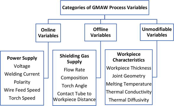
Figure 3.
Categories of GMAW process parameters [
3.1 Welding current
Welding current varies directly with wire feed speed or melting rate and an increase in electrode wire diameter necessitates an increase in current [1, 25]. Moreover, welding influences the metal transfer modes [1, 24], penetration [1], and bending strength [4].
3.2 Polarity
Polarity is defined by the electrode that is connected to the electrical terminal; direct current electrode positive (DCEP) or straight polarity is achieved when the wire electrode is connected to the positive terminal, while connecting the wire electrode to the negative terminal gives the direct current electrode negative (DCEN) polarity. DCEP polarity has a stable arc, smooth metal transfer [26], low spatter, good weld bead, and good penetration [5, 27]; consequently, it is the most desirable polarity [28]. The DCEN polarity produces large drop sizes and arc forces that propel drops away from the workpiece leading to an unstable arc [6]. In the review presented by Kah et al. [29], the alternating current gas-metal arc welding combines the benefit of arc stability of DCEP and high melting rate of DCEN, resulting in high weld quality that is useful in aluminum. Accordingly, the benefits of alternating current-gas metal arc welding (AC-GMAW) process include improved distortion control, reduced heat input, higher welding wire melting rate, and reduced dilution, resulting in higher deposition of filler wire with minimal heat input [29].
3.3 Arc length (arc voltage)
The arc length, which is the gap between the electrode tip and the base of the workpiece base, directly affects the arc voltage; the arc length is inversely proportional to the arc voltage, i.e., a high arc length causes a low arc voltage and vice versa [1, 5, 30]. Additionally, the arc sound pressure increases with an increase in arc voltage [27]. The arc voltage also influences the metal transfer mode [31, 32] and depth of penetration [33].
3.4 Travel speed
Travel speed, which is determined by the rate at which the GMAW torch moves, determines the amount of filler metal that is deposited. The depth of penetration [33] and weld bead geometry [32] are influenced by the travel speed; high filler metal is deposited at slow travel speed, while higher travel speed results in an insufficient filler metal deposition.
3.5 Electrode extension (stickout)
Electrode extension (stickout) is the distance between the contact tube tip and the end of the electrode. An increase in the electrode extension increases resistance causing the end of the electrode to melt before the actual welding, resulting in a reduction in weld heat, penetration, and fusion, and an increased buildup [1, 5].
3.6 Electrode orientation
Electrode orientation is the direction of travel, i.e., trailing and leading orientations. It influences the weld bead geometry and penetration more significantly than the influence of the arc voltage or travel speed on the bed geometry and penetration [5, 20, 30].
3.7 Electrode size
The electrode size influences the transfer mode, deposition rate and determines the amount of current and voltage to be set; a small electrode requires more time to deposit on a thick material, while a larger diameter requires higher current and voltage to be used [1, 5, 34].
3.8 Shielding gases
The main function of the shielding gas in the GMAW process is to protect the molten weld pool from contaminants in the atmosphere and prevent oxidation [23]. Therefore, the shielding gas controls the microstructure and composition of the weldment. The type of shielding gas and its flow rate have a great effect on arc characteristics, metal transfer mode, penetration and weld bead profile, weld speed, etc. A mixture of argon with 2–5% oxygen added, and argon with 25% carbon dioxide gas (CO2) added or 100% CO2 (active gas) are used when welding carbon steels [5, 30, 35]. The low gas flow rate can cause blow holes and porosity [17].
4. Weld quality characteristics
The welding quality characteristics that define the GMAW welds include: weld bead geometry (bead width and penetration), heat-affected zone (HAZ), microstructure and mechanical properties (strength, ductility, and hardness) of the weldment), and discontinuities (porosity and spatter) [20, 36, 37]. These weld quality characteristics—which are discussed in detail in the proceeding subsections—are influenced by input (process) parameters such as welding speed, current, wire feed speed, contact tip to workpiece distance, and voltage [1, 5, 19, 24]. The deposition rate is an important process variable that influences the weld quality characteristics.
4.1 Weld bead geometry
The weld bead geometry is characterized by convexity index, depth of penetration (bead penetration), bead height, bead width, and reinforcement area [20, 36, 38]. To obtain the desired quality characteristics, process parameters, such as welding speeds, current, wire feed speed, contact tip to workpiece distance, and voltage, are set on the welding equipment. However, it is hard to maintain these process parameters at a constant value throughout the welding duration due to external disturbances that may cause parameter variations resulting in some undesired quality, such as incomplete penetration, which can contribute to the failure of the welded structure. Proper selection and optimization of the process parameters enable attainment of acceptable weld bead penetration with a high-quality joint.
Different techniques, such as Taguchi experimental design, statistical analyses like analysis of variance (ANOVA), and numerical methods like artificial neural networks (ANNs), have been used to optimize and predict the effect of the process parameters on weld bead geometry [39]. Kalaignar et al. [40] used ANOVA to predict the most significant process parameters affecting weld bead geometry and concluded that welding speed was the major factor affecting the bead penetration and bead width; and that wire feed rate and welding speed were the most significant parameters affecting bead height [40]. A larger penetration is desirable and a smaller convexity index is a desirable quality characteristic [41].
4.2 Heat-affected zone (HAZ)
Heat-affected zone (HAZ) is the part of the metal that changes its properties due to the heat from welding, but does not melt, as shown in Figure 4 [42]. The features that define the HAZ are the width and grain size, which are influenced by the process parameters set on the welding equipment [35]. Moghaddam et al. [43] employed ANOVA on experimental results and determined that the most significant process parameters that influence HAZ were arc voltage and nozzle-to-plate distance. Too high values of arc voltage and nozzle-to-plate distance resulted in a high heat input, which in turn increased the HAZ and vice versa. Therefore, lower values of both arc voltage and nozzle-to-plate distance are desirable for achievement of the desired weld quality [43].

Figure 4.
Heat-affected zone [
4.3 Microstructure and mechanical properties of the weldment
The heat-affected zone (HAZ) corresponds to the part of the base metal that undergoes structural modifications due to welding. These alterations in the microstructure influence the composition of the welded area and require control, as defects in welding are closely linked to the microstructure of this zone. The microstructure’s configuration is interconnected with the mechanical characteristics of the weldment. The arrangement of the microstructure is significantly influenced by the material’s chemical composition and the heating and cooling cycles it experiences [44, 45]. Wire feed rate is the most important parameter that affects the HAZ microstructure, as it changes the heat input and cooling rate. Lower wire feed rate leads to smaller HAZ area and ferrite-rich microstructure with some cementite (Fe3C) or austenite. Voltage and welding speed have less influence, and they cause some Widmanstatten Ferrite (WF) and pearlite in the HAZ due to different cooling cycles. The HAZ microstructure is mainly ferrite and pearlite [46].
The HAZ is the part of the base metal that changes its microstructure due to welding. This affects the quality of the weldment and depends on the material’s chemistry and the heating and cooling cycles. Wire feed rate is the key parameter that controls the HAZ microstructure of low-carbon steel, as it affects the heat input and cooling rate. Lower wire feed rate makes the HAZ smaller and richer in ferrite with some Fe3C or austenite. Voltage and welding speed have less effect, and they produce some Widmanstatten Ferrite (WF) and pearlite in the HAZ due to different cooling cycles. The HAZ microstructure is mainly ferrite and pearlite [43, 47].
Figure 5 shows that different microstructures of low-carbon steel are formed under varying welding conditions. The microstructures of similar lead and trail currents and dissimilar currents are clearly visible in the corresponding weld metal (WM) and HAZ. This leads to a corresponding change in the hardness. The size of the grain, its shape (bainitic or polygonal/lath-like or granular), and the composition of phases (bainite/ferrite/pearlite) present determine the hardness in the WM and HAZ. The similarity in hardness values in the HAZ of samples 1 and 2 corroborates the similarity in volume fraction of ferrite grains present. The WM for sample 3 consists of a higher composition of lath-like grains (bainitic ferrite) and some laths are very fine with fine white dots (probably bainite) when compared to sample 4 where large lath-like and granular grains (bainitic and polygonal ferrite, respectively) are dominant. The HAZ for sample 4 also shows softening as it consists of granular ferrite with large grains with very little presence of bainite or pearlite, whereas the HAZ for sample 3 consists largely of granular ferrite with smaller grains, which is responsible for greater hardness [47].

Figure 5.
Microstructures for different wire diameters and welding current [
In another experimental study, the effect of changing process parameters, such as current, voltage, root gap, welding rate, and shielding gas flow rate, also showed the change in mechanical properties (ultimate tensile strength (UTS), impact value, root bend, and microstructure) of weldment. The three weldments tested were found to have a microstructure consisting mainly of ferrite grains with a small amount of pearlite. Weldment 2 had finer and more elongated grains than weldment 1 and weldment 3. The specimen of weldment 2 exhibits higher UTS than the other specimens [44]. In a study on the effects of changing varying current, voltage, and number of passes on mechanical properties of HAZ, it was found out that the increase in current increases the hardness, increase in voltage increases the depth of penetration, and increase in the number of passes decreases the hardness [45].
The impact of heat input on the microstructures of two carbon steels with different carbon levels was investigated in a study. For low-carbon steel, there was a decrease in the pearlite with an increase of heat input causing coarser microstructure in the HAZ, while high-carbon steel showed that there was an increase in the pearlite with an increase of heat input causing less coarse microstructure in the HAZ, indicating that high-carbon steel has better mechanical properties and is more resistant to heat input effects [48].
4.4 Discontinuities (porosity and spatter)
According to the American Welding Society (AWS) publication “Standard Welding Terms and Definitions” (AWS A3.0:2001), a “discontinuity” is termed as a disruption in the normal structure of a material which hinders uniformity of its mechanical, metallurgical, or physical properties. In fact, not all discontinuities are considered to be defects. A defect can be a gap in the material that can minimize the accepted standard of a product. A flaw is can be termed as an unwelcome discontinuity. The size and shape of discontinuities vary and bigger size and shapes can minimize weld quality [9].
Porosity, a type of discontinuity in welding, emerges when gas becomes trapped within a weld, leading to the creation of circular or elongated voids, either on the surface or beneath it, as shown in Figure 6a [9]. In processes like arc welding, this phenomenon results from gases that are normally dissolved within the molten weld material. If the concentration of these dissolved gases surpasses their capacity to dissolve, the excess gas is expelled from the solution as bubbles or gas pockets during the solidification phase of the weld material [49]. Some causes of porosity are impurities, insufficient shielding, erratic arc, short arc gap, and low-quality welding skill in general [50].

Figure 6.
(a) Clustered porosity and (b) weld spatter [
Surface irregularities are flaws on the weld surface that may affect the weld quality and performance. They include ripples, spatters, craters, arc strikes, and pores. Spatter denotes the presence of melted metal fragments that do not properly blend into the weld, possibly indicating problems with the welding procedure or insufficient skill [9]. This issue encompasses the formation of liquid droplets close to the welding arc while welding and their subsequent expulsion from the weld pool, as shown in Figure 6b. Multiple factors can trigger this expulsion of melted material, including issues like unsuccessful arc initiation. Insufficiently fine-tuned settings frequently play a role in causing spatter. The consequences of spatter can encompass substandard weld quality, disorderly workspaces, and wastage of materials. Moreover, the removal of spatter from the surfaces of workpieces prolongs production time and raises costs [49].
Sefton and James [51] carried out a research that focused on the challenge posed by GMA welding’s sensitivity to strong air currents. They explored the consequences of altering air velocities and shielding gas rates during welding while maintaining consistent other conditions. A specialized apparatus ensured precise airflow control. At draught speeds as modest as 0.9 m/s, the shielding gas dispersed and polluted the weld, resulting in the emergence of porosity, a notable defect. Elevated gas flows without air disruption prevented porosity. Amplified draught speeds and particular gas flows corresponded to heightened porosity, reducing the weld’s strength. The study also observed spatter, with porosity as the primary influencer of spatter levels. In fact, the higher the porosity, the higher the spatter and vice versa [51].
5. Characteristics of carbon steel
Carbon steel is among the commercially important metals with intrinsic mechanical properties, low cost, abundant sources, and high melting temperatures that lead to their intensive and extensive use in various economic sectors such as engineering, transportation, agriculture, and information technology [3, 48, 52, 53]. Various types of carbon steel include the low-carbon steel that comprises not more than 0.20% C, medium-carbon steel that contains the carbon percentage between 0.20 and 0.50%, and high-carbon steel that has more than 0.50% C [42]. The carbon content and alloying elements added determine the characteristics of carbon steel. These characteristics include hardenability, strength, hardness, toughness, wear resistance, workability, weldability, and machinability [54].
5.1 Chemical composition of carbon steel
Chemical composition can be defined as a combination of different elements that make up a chemical substance. A combination of iron (Fe) and carbon (C) coupled with suitable alloying elements makes up carbon steel. The chemical composition of carbon steels varies with the carbon content where low-, medium-, and high-carbon content corresponds with the respective carbon steel types. The common alloys added to carbon steels or that occur as impurities include manganese, phosphorus, sulfur, silicon, copper, nickel, and chromium, among others. Generally, every alloying element composed in the carbon steel material has either negative or positive contributions to its inherent properties and characteristics that include hardenability, strength, hardness, toughness, wear resistance, workability, weldability, and machinability. In fact, the higher the alloying content, the greater the effects it imparts on carbon steel. The chemical composition in the weld metal is basically the combination of base metal and electrode metal compositions. For example, high-carbon content increases the strength, hardness, and wear resistance while it reduces the ductility, weldability, and toughness of the carbon steels [54]. The chemical composition of the weld interface and heat-affected zone is similar to that of the base metal. However, the mechanical properties may differ depending on the cooling rates and temperatures expressed during the welding process [42].
5.2 Welding characteristics of carbon steel
All carbon steels can be welded with low-carbon steel exhibiting a high rate of weldability due to the low-carbon equivalent value which disregards the need for preheat and postheat treatment controls as in the case of high-carbon steel [51, 52]. This chapter examines previous studies and argues that it is important to distinguish between weld characteristics and welding characteristics. These terms may seem similar, but this analogy is not true. Weld characteristics are the properties of a carbon steel-welded joint such as mechanical properties like tensile strength, hardness, elongation, and impact energy [55]. Welding characteristics are the behaviors and qualities of carbon steel during the welding process. These welding characteristics encompass a range of factors that describe how well a welding process performs and how effectively it joins materials. These factors include the welding process parameters, preheat temperature, interpass temperature, and postweld heat treatment, carbon content, cooling rate, joint design, filler material, base metal conditions, alloying elements, and heat input [24, 56, 57, 58]. According to B. Choudhury and Chandrasekaran [58], the weld bead geometry (shape and size of the weld bead) and the strength (force it can withstand) are examples of welding characteristics that measure weld quality [58].
6. Fundamental principle of the GMAW process control
6.1 GMAW process dynamics
Gas-metal arc welding process dynamics refer to the aspect of rapid changes in the GMAW process variables during the welding process which influences the metal transfer dynamics. The GMAW process experiences dynamic changes in the different components of the GMAW system, which include power supply, wire electrode feed, shielding gas supply, and power and work leads [1]. These components of the GMAW system contribute to the disturbances and uncertainties in the GMAW process [59]. The welding process should be stable to give desired weld quality; however, stability of the welding process is not possible due to disturbances and uncertainties over which the welder has no control, resulting in weld defects like spatter, porosity, excessive light, and fumes [60].
To develop mechanisms for overcoming the disturbances and uncertainties observed during GMAW process, several researchers have developed mathematical (statistical and numerical) models that describe the physical GMAW process by employing fundamental principles of science, statistical and/or experimental techniques [6, 12, 13, 32, 40, 41], and artificial intelligence models [14, 15, 59]. The major aim of these models is to provide a framework for describing and understanding the behavior of the GMAW system in order to provide an effective feedback control [6]. Dynamic models developed have either focused on the specific dynamic behavior of the power source [61], metal transfer [62, 63], arc and droplet [64], and weld pool dynamics [65]. The dynamic models have focused on adjustment of the process parameters to attain the desired heat input and mass flow to the molten pool, which directly influences the weld geometry and greatly improves the weld quality [13].
6.2 GMAW process control
Process control of robotic or automatic equipment involves regulating the sequence of operations, process variables, multiple schedules, and motion in order to produce the desired response [9]. The most common process controllers used in the GMAW process include: Proportional-Integral-Derivative (PID), Integral Sliding Mode Controller (SMC), Model Predictive Control (MPC), Adaptive Control, and Intelligent Control.
7. Weld quality measurement systems
7.1 Online weld quality systems
The GMAW process characteristics—such as extreme brightness of the arc radiation, spatters/splash of the hot metal, fumes/smokes, high temperatures—inhibit the welder (operator) from clearly viewing the molten weld pool dynamics and the formed weld bead during the welding process. Therefore, online monitoring is used to continuously compare the actual and desired weld quality values so as to adjust the welding parameters based on such real-time sensing and feedback control [77]. An online weld quality measurement system is the quality measurement inspection done during the welding process. A sensor mounted on the robot head scans the welded surface and sends the analyzed measured data to the welder (operator) or control algorithm, as shown in Figure 7 [78]; and subsequently, adjustments in the input process parameters can be made. The benefits of using an online weld quality measurement system include higher productivity, lower costs due to limited final inspection, less audit, less repair, and greater reliability of the welded components in automated welding operations, which subsequently guarantees good weld quality [79, 80]. Online weld quality systems have been used to satisfactorily measure weld bead dimensions (groove width, weld bead width, filling depth, and reinforcement height) and detect weld defects (plate displacement, weld bead misalignment, and undercut) [81].

Figure 7.
Real-time scanning using a laser scanner mounted on the robot head [
Intelligent models, analytical and simulation techniques, such as soft-computing tools, finite element methods, and thermal models for online monitoring, have been developed to improve the online monitoring of the weld quality [27]. Online monitoring can also be obtained using data mining algorithms that detect the process disturbance with the statistical data [82]. Advanced (i.e., reliable, noncontact, and nondestructive) online sensors used to [80] extract data from the GMAW welding process include fuzzy-logic-based optical sensors, laser profile sensors [78], and the hall effect sensor [82]. The usability of the online sensors’ quality assessment and diagnosis is limited by their speed, time of evaluation (delayed evaluation or postprocess evaluation), cost, robustness, and accessibility. Arc sensing provides more flexible online sensing but is also limited by directly measuring only the input and the intermediate variables of the process without detecting the output variables, so it does not give the information about the weld quality. Consequently, Ayoade and Steele [5] experimentally investigated both arc sensing data collection for in-process and sensor technology sensing for postprocess data inspection to establish the method that provided better weld quality [5]. Online surface measurement is also important for determining weld quality in Wire Arc Additive Manufacturing (WAAM) using the GMAW process, whereby online surface measurement is used to measure each layer of metal added in order to ensure that the desired bead geometry is obtained before the next layer is laid; the bead geometry determines the quality of the next layer [83].
7.2 Offline weld quality systems
Offline weld quality measurement is a postwelding inspection or nondestructive testing (NDT) technique for identifying defects in which the weld bead is measured after welding or away from the welding station to check whether the desired quality has been achieved [82]. Offline weld quality measurement is time-consuming and costly [27]. Welded surface beads can be measured using numerous handheld manual gauges that measure the weld toe radius shown in Figure 8 [78]. Vision systems are other tools that are used in weld quality measurement by scanning the welded surface and a computerized environment is used for evaluation and that assessment is done by manually placing measurement points (a minimum of 3 points) in the area of interest on the cross-section curve of the measured surface [78].

Figure 8.
Manual weld geometry measurement gauges: (a) radius gauge, (b) radius master, and (c) gauge for throat thickness and depth of undercut [
8. Weld quality standards
The presence of discontinuities and imperfections is a common occurrence in welded structures; therefore, an appropriate standard must be satisfied by a specific weld so that the welded products can be considered to be fit for service in a specific application without failure [24].
8.1 International standard SS-EN ISO 5817
The international standard SS-EN ISO 5817 is a standard applicable to a wide range of welded fabrications, which provides quality levels of imperfection in fusion welded butt and fillet joints (except for beam welding) in all types of steel, nickel, titanium, and their alloys; the SS-EN ISO 5817 is applicable to material thickness ≥ 0.5 mm and covers fully penetrated butt welds and all fillet welds as well as partial-penetrated butt welds. The standard provides three classifications of quality levels designated by symbols B, C, and D, where B is the highest and D has the lowest requirements on the finished welds for each weld discontinuity and imperfection [80, 81]. The standard specifies more than 40 different discontinuities and weld imperfections for the different quality levels [78], with 23 outside imperfections, 13 inside imperfections, two weld geometry imperfections, and two types of multiple imperfections [84]. The SS-EN ISO 5817 standard was established when stress analysis was based on simple strength of materials calculations (nominal methods) and the acceptance limits were set from a production point of view of good workmanship [85]. However, an inconsistency between acceptance limits according to the SS-EN ISO 5817 standard and fatigue life exists within the same quality level where some existing imperfection types lead to short fatigue life, other imperfection types lead to long fatigue life while some other imperfection types do not influence fatigue life [79, 81].
8.2 Volvo group STD 181: 0004
The Volvo Group STD 181–0004 standard was developed to mitigate the inconsistencies of the SS-EN ISO 5817, which featured a weak relationship between the acceptance limits and the influence of existing imperfections on the fatigue life. The Volvo Group STD 181–0004 standard has five quality levels whereby four quality levels (VE, VD, VC, and VB) are for fatigue-loaded structures and one for static-loaded structures (VS) within general lower demands. Quality level VE, which has the lowest requirements regarding discontinuities, is used for welds where the root and weld penetration is critical; VD is used for as-welded normal quality, VC is used for as-welded high quality, and the highest level VB stands for B posttreated welds [81, 84].
According to Jonsson et al. [82], the Volvo Group STD 181–0004 standard achieves a more consistent weld quality compared to SS-EN ISO 5817, according to the following three important principles:
The same fatigue life should be attainable for all imperfection types in one weld quality class level.
A shift from one weld class level to the next weld class level reflects a 25% increase in fatigue strength, which is a factor-of-2 increase in fatigue life.
Only imperfection types that influence fatigue strength are defined in the different classes.
8.3 IIW guidelines on weld quality
The International Institute of Welding (IIW) guidelines on weld quality quantitatively relate weld acceptance criteria to the expected structural performance in terms of fatigue strength [85]. The IIW guidelines on weld quality ensure that the welded joint’s imperfections meet the fatigue strength demands, which are defined in S-N curves for different fatigue assessment methods. The IIW guidelines on weld quality define acceptance criteria based on weld geometry and imperfections with a focus on increased fatigue strength [78].
9. Conclusion
Significant weld quality improvements have been achieved by GMAW process dynamics modeling and coupled with adaptive controls that refine process parameter inputs. Online and offline weld quality measurements have been combined to create better weld surface geometry measurements, resulting in the adjustment of process parameters for control of the weld quality. The welding process parameters play a critical role in determining the microstructure and mechanical properties of carbon steel. Therefore, to achieve the required microstructure and mechanical properties while minimizing weld defects, the welding process parameters need to be controlled and optimum welding process parameters need to be found. The process parameters have an effect of changing the microstructure and mechanical properties of carbon steel. Moreover, significant advancements have been made in the areas of sensor technologies and computational power for online and offline weld quality measurement systems of the weld surface geometry has enabled the realization of intelligent automated GMAW processes. Consequently, smart manufacturing with smarter robot welding units, more-intelligent process control, and automated quantitative quality inspections within the welding industry has been realized [5]. The IIW guidelines on weld quality provide acceptance criteria for high-quality weld structures, therefore, the desired weld quality characteristics can be achieved. Furthermore, Smart manufacturing, a technology of the Fourth Industrial Revolution (4IR) (also referred to as Industry 4.0), is now beginning to take center stage in the development of industrial processes. Therefore, efforts are being put into developing smarter welding intelligent technologies that are capable of recognizing abnormalities in the weld, identifying the cause of the weld defect, and making immediate necessary corrective actions leading to weld quality improvement without human intervention.
References
- 1.
Jeffus L. Welding and Metal Fabrication. Boston, Massachusetts: Cengage Learning; 2012 - 2.
Elaru P. Improving project based learning to enhance trainees. In: Skills Acquisition in Welding and Metal Fabrication at Buhimba Technical Institute in Hoima. Kampala, Uganda: Kyambogo University; 2019 - 3.
Chavda SP, Desai JV, Patel TM, Ksv L. A review on parametric optimization of MIG welding for medium carbon steel using FEA-DOE hybrid Modeling. International Journal of Science and Research Development. 2013; 1 (9):3-6 - 4.
Pandhare V, Rai P, Lad BK, Das S, Sabiruddin K. Determination of significant factors affecting the bending strength of weld joint prepared by gas metal arc welding. Journal of Mechanical Engineering Research and Technology. 2016; 2 (1):1-12. Available from:http://www.ijmert.net/Current-Issue.php - 5.
Ayoade AA, Steele JPH. Welding heterogeneous measurement system for data mining robotic GMAW weld quality. Welding Journal. 2022; 101 :96-110. DOI: 10.29391/2022.101.008 - 6.
Naidu DS, Dzcelik S, Moore KI. Modeling, Sensing and Control of Gas Metal Arc Welding. 2003 - 7.
Chitrambalam ST, Ming TW, Mohammad IS, Mat SB. A study on relationship between process variables and weld penetration for gas metal arc welding (GMAW). International Conference and Exhibition on Sustainable Energy and Advanced Materials. 2011:237-244 - 8.
Jeet S, Sahoo BB, Barua A, Parida B, Kumar Bagal D. A study on relationship between process variables and weld penetration for gas metal arc welding (GMAW). International Journal of Technical Innovation in Modern Engineering & Science. 2018; 4 (8):683-692. Available from:https://www.researchgate.net/publication/327228295 - 9.
O’Brien ACLJ. Welding Handbook: Welding Science and Technology. Ninth Edit. ed. Vol. 1. Miami: American Welding Society; 2001 - 10.
Ssempijja D. Investigations into the Mechanical Performance of Ugandan Made Carbon Steel Bars. Kampala, Uganda: Kyambogo University; 2019 - 11.
Gyasi EA, Handroos H, Kaha P. Survey on artificial intelligence (AI) applied welding: A future scenario of the influence of AI on technological, economic, educational and social changes. In: 29th International Conference on Flexible Automation and Intelligent Manufacturing (FAIM2019). Vol. 38. 2019. pp. 702-714. DOI: 10.1016/j.promfg.2020.01.095 - 12.
Chandrasekaran RR, Benoit MJ, Barrett JM, Gerlich AP. Multi-variable statistical models for predicting bead geometry in gas metal arc welding travel speed. International Journal of Advanced Manufacturing Technology. 2019; 105 :1573-1584. DOI: 10.1007/s170-019-04355-0 - 13.
Park JH, Cho DW, Moon HS. CFD simulation of molten pool dynamic behavior on vertical-downward position in P-GMAW process. International Communications in Heat and Mass Transfer. 2022; 132 (105876):1-17. DOI: 10.1016/j.icheatmasstransfer.2021.105876 - 14.
Hu Z, Hua L, Qin X, Ni M, Ji F, Wu M. Molten pool behaviors and forming appearance of robotic GMAW on complex surface with various welding positions. Journal of Manufacturing Processes. 2021; 64 (January):1359-1376. DOI: 10.1016/j.jmapro.2021.02.061 - 15.
Rohe M, Stoll BN, Hildebrand J, Reimann J, Bergmann JP. Detecting process anomalies in the gmaw process by acoustic sensing with a convolutional neural network (Cnn) for classification. Journal of Manufacturing Materials Process. 2021; 5 (4):1-17. DOI: 10.3390/jmmp5040135 - 16.
He Y, Li D, Pan Z, Yu L, Yuan H, Le J. Dynamic modeling of weld bead geometry features in thick plate GMAW based on machine vision, Mdpi. 2020; 20 (7104):1-18. DOI: 10.3390/s20247104 - 17.
Srivastava S, Garg RK. Process parameter optimization of gas metal arc welding on IS:2062 mild steel using response surface methodology. Journal of Manufacturing Processes. 2017; 25 :296-305. DOI: 10.1016/j.jmapro.2016.12.016 - 18.
Terner M, Bayarsaikhan TA, Hong HU, Lee JH. Influence of gas metal arc welding parameters on the bead properties in automatic cladding. Journal of Welding and Joining. Feb 2017; 35 (1):16-25. DOI: 10.5781/jwj.2017.35.1.16 - 19.
Lorza RL, García EM, Rubén FCR, Martínez MÁ. Using Genetic Algorithms with Multi-Objective Optimization to Adjust Finite Element Models of Welded Joints. 2018. DOI: 10.3390/met8040230 - 20.
Zhao S, Qiu X, Burnett I, Rigby M, Lele A. Statistical characteristics of gas metal arc welding (GMAW) sound. In: Proceedings of the 23rd International Congress on Acoustics. 2019. pp. 7594-7601. DOI: 10.18154/RWTH-CONV-238970 - 21.
Antonini JM. Health, safety and environmental issues. In: Saleem Hashmi BM, Van Tyne CJ, Batalha GF, editors. Comprehensive Materials Processing. Amsterdam, Netherlands: Elsevier; 2014 - 22.
Kaputska N. Reciprocating Wire Feed GMAW – An Advanced Short Circuit GMAW Mode. 2014. Available from: https://ewi.org/reciprocating-wire-feed-gmaw-an-advanced-short-circuit-gmaw-mode/EWI - 23.
Dinbandhu V, Prajapati JJV, Abhishek K. Advances in gas metal arc welding process: Modifications in short-circuiting transfer mode. In: Davim JP, Gupta K, Gupta K, editors. Handbooks in Advanced Manufacturing, Advanced Welding and Deforming. Amsterdam, Netherlands: Elsevier; 2021. pp. 67-104. DOI: 10.1016/b978-0-12-822049-8.00003-7 - 24.
Jeffus L. Welding: Principles and Applications. Boston, Massachusetts: Cengage Learning; 2017 - 25.
Balamurugan S, Senthilkumar B, Kannan T, Surendran P. Influence of welding process parameters on bead geometry - A review. Journal of Mechanical Engineering. 2015; 1 (3). Available from:https://www.researchgate.net/publication/301503796 - 26.
Pires I, Quintino L, Miranda RM. Analysis of the influence of shielding gas mixtures on the gas metal arc welding metal transfer modes and fume formation rate. Materials and Design. 2007; 28 (5):1623-1631. DOI: 10.1016/j.matdes.2006.02.012 - 27.
Pal KP, Bhattacharya S, SK. Investigation on arc sound and metal transfer modes for on-line monitoring in pulsed gas metal arc welding related papers, Journal of Materials Processing Technology. 2010; 210 :1397-1410. DOI: 10.1016/j.jmatprotec.2010.03.029 - 28.
Bazargan-Lari Y, Eghtesad M, Assadsangabi B. Study of internal dynamics stability and regulation of globular-Spray mode of GMAW process via MIMO feedback-linearization scheme. In: 12th International Conference on Intelligent Engineering Systems. 2008. pp. 31-36 - 29.
Kah P, Suoranta R, Martikainen J. Advanced Gas Metal Arc Welding Processes. 2013. pp. 655-674. DOI: 10.1007/s00170-012-4513-5 - 30.
Somani CA, Lalwani DI. Experimental investigation of gas metal arc welding (GMAW) process using developed articulator. IOP Conference Series: Materials Science and Engineering. 2018; 455 (012073):1-8. DOI: 10.1088/1757-899X/455/1/012073 - 31.
Praveen P, Kang MJ, Incheon Y, Korea S. Arc voltage behavior in GMAW-P under different drop transfer modes. Manufacturing Engineering. 2009; 32 (2):196-202 - 32.
Kumar A, Khurana MK, Yadav PK. Optimization of gas metal arc welding process parameters. IOP Conference Series: Materials Science and Engineering. 2016; 149 (1):1-11. DOI: 10.1088/1757-899X/149/1/012002 - 33.
Ibrahim IA, Mohamat SA, Amir A, Ghalib A. The effect of gas metal arc welding (GMAW) processes on different welding parameters. Procedia Engineering. 2012; 41 :1502-1506. DOI: 10.1016/j.proeng.2012.07.342 - 34.
Rao ZH, Hu J, Liao SM, Tsai HL. Modeling of the transport phenomena in GMAW using argon – Helium mixtures. International Journal of Heat and Mass Transfer. 2010; 53 :5707-5721. DOI: 10.1016/j.ijheatmasstransfer.2010.08.009 - 35.
Adak DK, Mukherjee M, Pal TK. Development of a direct correlation of bead geometry, grain size and HAZ width with the GMAW process parameters on bead-on-plate welds of mild steel. Transactions of the Indian Institute of Metals. 2015; 68 (5):839-849. DOI: 10.1007/s12666-015-0518-8 - 36.
Mvola B, Kah P, Layus P. Review of current waveform control effects on weld geometry in gas metal arc welding process. International Journal of Advanced Manufacturing Technology. 2018; 96 (9-12):4243-4265. DOI: 10.1007/s00170-018-1879-z - 37.
Penttilä S, Kah P, Ratava J, Eskelinen H. Artificial neural network controlled GMAW system: Penetration and quality assurance in a multi-pass butt weld application. International Journal of Advanced Manufacturing Technology. 2019; 105 (7-8):3369-3385. DOI: 10.1007/s00170-019-04424-4 - 38.
Gyasi EA, Kah P, Penttilä S, Ratava J, Handroos H, Sanbao L. Digitalized automated welding systems for weld quality predictions and reliability. Procedia Manufacturing. 2019; 38 (2019):133-141. DOI: 10.1016/j.promfg.2020.01.018 - 39.
Sreeraj P, Kannan T, Subhashis M. Simulation and parameter optimization of Gmaw process using neural networks and particle swarm optimization algorithm. International Journal of Mechanical Engineering and Robotics Research. 2013; 2 (1):130-146 - 40.
Kalaignar R, Rengarajan S, KrishnaMohan P. An investigation and welding characterization of dissimilar joints of alloy steel with SS 410 through. International Journal of Emerging Engineering Research and Technology. 2017; 5 (6):35-40 - 41.
Sen M, Mukherjee M, Pal TK. Evaluation of correlations between DP- GMAW process parameters and bead geometry. Welding Journal. 2015; 94 (8):265-279 - 42.
Groover MP. Fundamentals of Modern Manufacturing: Materials, Processes, and Systems. Fourth Edi ed. Hoboken: John Wiley & Sons, Inc.; 2010 - 43.
Moghaddam MA, Golmezerji R, Kolahan F. Simultaneous optimization of joint edge geometry and process parameters in gas metal arc welding using integrated ANN-PSO approach. Scientia Iranica. 2017; 24 (1):260-273. DOI: 10.24200/sci.2017.4031 - 44.
Phogat S, Singh R. Experimental study of effect of process parameter of GMAW welding on mechanical properties and microstructure of steel (SAILMA 350 HI). International Journal of Applied Mechanics. 2017; 12 (1):113-123. Available from:http://www.ripublication.com - 45.
Sura N, Singh K. Experimental study on effects of process parameters on HAZ of plain carbon steel using GMAW. In: International Conference on Emerging Trends in Science & Technology (ICETST). Vol. 11. 2018. pp. 9-14. Available from: https://www.researchgate.net/publication/325417305 - 46.
Tawfeek T. Study the influence of gas metal arc welding parameters on the weld metal and heat affected zone microstructures of low carbon steel. International Journal of Engineering & Technology. 2017; 9 (3):2013-2019. DOI: 10.21817/ijet/2017/v9i3/1709030272 - 47.
Moinuddin SQ , Kapil A, Kohama K, Sharma A, Ito K, Tanaka M. On process-structure-property interconnection in anti-phase synchronised twin-wire GMAW of low carbon steel. Science and Technology of Welding and Joining. 2016; 21 (6):452-459. DOI: 10.1080/13621718.2015.1124960 - 48.
Syahida N, Nasir M, Khairul M, Abdul A, Ahmad MI. Influence of heat input on carbon steel microstructure. ARPN Journal of Engineering and Applied Sciences. 2017; 12 (8):2689-2697 - 49.
Ghazvinloo HR, Honarbakhsh- Raouf A, Shadfar N. A comprehensive study on the welded joints appearance in GMAW. Journal of Materials and Environmental Science. 2021; 2021 (10):12. Available from:https://www.researchgate.net/profile/Hamid-Reza-Ghazvinloo/publication/366722992_A_comprehensive_study_on_the_welded_joints_appearance_in_GMAW/links/63b03814097c7832ca7d360c/A-comprehensive-study-on-the-welded-joints-appearance-in-GMAW.pdf - 50.
Raj M. Effect of Process Parameters on Mechanical Properties in GMAW. Delhi: Delhi Technological University; 2016 - 51.
Mamo S, Foden J. Understanding the shielding gas dynamics and improving the weld quality in MIG /MAG welding with respect to draughts. Science, Research and Development. 2013:61-80 - 52.
Odebiyi OS, Adedayo SM, Tunji LA, Onuorah MO. A review of weldability of carbon steel in arc-based welding processes. Cogent Engineering. 2019; 6 (1):1-32. DOI: 10.1080/23311916.2019.1609180 - 53.
Prakash SO, Karuppusway P, Gandhi BS. Enhancing the notch tensile strength of GMAW welded AISI 1013 low carbon steel with taguchi optimization. Samriddhi: A Journal Of Physical Sciences, Engineering And Technology. 2021; 13 (01):20-25. DOI: 10.18090/samriddhi.v13i01.5 - 54.
Kalpakjian S, Schmid SR. Manufacturing Engineering and Technology. Sixth Edit ed. Singapore: Prentice Hall; 2009 - 55.
Campbell SW, Galloway AM, McPherson NA. Artificial neural network prediction of weld geometry performed using GMAW with alternating shielding gases. Welding Journal. 2012; 91 (6):174s-181s - 56.
Khan MS, Bhole SD, Chen DL, Boudreau G, Biro E, Deventer JV. Resistance spot welding characteristics and mechanical properties of galvannealed HSLA 350 steel. Canadian Metallurgical Quarterly. 2009; 48 (3):303-310. DOI: 10.1179/cmq.2009.48.3.303 - 57.
Chavda SP, Desai JV, Patel TM. A review on optimization of MIG welding parameters using Taguchi’s DOE method. International Journal of Engineering & Management Research. 2014; 4 (1):2250-2758 - 58.
Choudhury B, Chandrasekaran M. Investigation on welding characteristics of aerospace materials - A review. Materials Today: Proceedings. 2017; 4 (8):7519-7526. DOI: 10.1016/j.matpr.2017.07.083 - 59.
Wong Y, Ling S. Novel classification method of metal transfer modes in gas metal arc welding by real time input electrical impedance. Science and Technology of Welding and Joining. 2014; 19 . DOI: 10.1179/1362171813Y.0000000184 - 60.
Galeazzi D, Régis HG e S, Pigozzo IO, da Rosa AF, Pereira AS, Marques C. Analysis of current pulse during short-circuit phase in CMT version of GMAW process under a view of additive manufacturing. International Institute of Welding. 2022; 66 :1-13. DOI: 10.1007/s40194-022-01298-1 - 61.
Dutra JC, Silva RHGE, Bernardi RA, Schwedersky MB, Marques C, Riffel KC. A new interpretative basis for the high performance GMAW process. Soldagem e Inspecao. 2021; 26 (2620):1-8. DOI: 10.1590/0104-9224/SI26.20 - 62.
Zhang YM, Yang YP, Zhang W, Na SJ. Advanced welding manufacturing: A brief analysis and review of challenges and solutions. Journal of Manufacturing Science and Engineering, Transactions of the ASME. 2020; 142 (11):1-33. DOI: 10.1115/1.4047947 - 63.
Ribeiro RA, Dos Santos EBF, Assunção PDC, Braga EM, Gerlich AP. Cold wire gas metal arc welding: Droplet transfer and geometry. Welding Journal. 2019; 98 (5):135S-149S. DOI: 10.29391/2019.98.011 - 64.
Chen SJ, Wang LW, Xiao J, Wei PS. Arc behavior and droplet dynamics of AC GTAW-GMAW hybrid indirect arc. Welding Journal. 2018; 97 (3):91S-98S. DOI: 10.29391/2018.97.008 - 65.
Mariappan M, Parthasarathi NL, Ravindran R, Lenin K, Raja A. Effect of alternating shielding gases in gas metal arc welding of SA515 gr 70 carbon steel. Materials Research Express. 2021; 8 (9):1-17. DOI: 10.1088/2053-1591/ac21e9 - 66.
Trigos AE, Garcia-Guarin J, Espinel Blanco EE. Design of a PID control for a prototype of an automated GMAW welding bench. Journal of Physics Conference Series. 2019; 1257 (1):1-8. DOI: 10.1088/1742-6596/1257/1/012001 - 67.
Hamouda N, Babes B, Boutaghane A, Kahla S, Talbi B. An Enhanced MPPT Method Combining Fractional-Order and Fuzzy Logic PID Controller for a Photovoltaic-Wire Feeder System (PV-WFS). Vol. 174. Heidelberg, Germany: Springer International Publishing; 2021. DOI: 10.1007/978-3-030-63846-7_12 - 68.
Bera MK, Bandyopadhyay B, Paul AK. Integral sliding mode control for GMAW systems. IFAC Proceedings. 2013; 10 (PART 1):337-342. DOI: 10.3182/20131218-3-IN-2045.00121 - 69.
Bera MK, Lal Priya PS, Bandyopadhyay B, Paul AK. Discrete-time Sliding Mode Control of GMAW Systems using Infrequent Output Measurements. 2013. DOI: 10.0/Linux-x86_64 - 70.
Bera MK, Bandyopadhyay B, Paul AK. Robust nonlinear control of GMAW systems-a higher order sliding mode approach. In: Proceedings of the IEEE International Conference on Industrial Technology. 2013. pp. 175-180. DOI: 10.1109/ICIT.2013.6505668 - 71.
Bera MK, Bandyopadhyay B, Paul AK. Variable gain super-twisting control of GMAW process for pipeline welding. The Journal of Dynamic Systems, Measurement, and Control Transactions of the ASME. 2015; 137 (7):1-7. DOI: 10.1115/1.4029408 - 72.
Penttilä S, Kah P, Ratava J, Pirinen M. Penetration and quality control with artificial Neural Network welding system. In: 27th International Ocean and Polar Engineering Conference. San Francisco, United States: ISOPE. 25 June 2017. pp. 54-61 - 73.
Xia C et al. Model predictive control of layer width in wire arc additive manufacturing. Journal of Manufacturing Processes. 2020; 58 (August):179-186. DOI: 10.1016/j.jmapro.2020.07.060 - 74.
Sartipizadeh H, Haeri M. Control of droplet detachment frequency in a GMAW process by a hybrid model predictive control. The Journal of Dynamic Systems, Measurement, and Control Transactions of the ASME. 2018; 140 (11):1-10. DOI: 10.1115/1.4040251 - 75.
Kah P, Shrestha M, Hiltunen E, Martikainen J. Robotic arc welding sensors and programming in industrial applications. International Journal of Mechanical and Materials Engineering. 2015; 10 (1):1-16. DOI: 10.1186/s40712-015-0042-y - 76.
Thompson R, Absi Alfaro SC. Intelligent control proposition on gmaw process with machine learning techniques. In: 25th ABCM International Congress of Mechanical Engineering, 2019. 2021. DOI: 10.26678/abcm.cobem2019.cob2019-0263 - 77.
Cheng Y, Yu R, Zhou Q , Chen H, Yuan W, Zhang Y. Real-time sensing of gas metal arc welding process – A literature review and analysis. Journal of Manufacturing Processes. 2021; 70 :452-469 - 78.
Stenberg T, Barsoum Z, Åstrand E, Öberg AE, Schneider C, Hedegård J. Quality control and assurance in fabrication of welded structures subjected to fatigue loading. Weld World. 2017; 61 :1003-1015. DOI: 10.1007/s40194-017-0490-5 - 79.
Wu CS, Polte T, Rehfeldt D. Gas metal arc welding process monitoring and quality evaluation using neural networks. Science and Technology of Welding and Joining. 2000; 5 :324-328. DOI: 10.1179/136217100101538380 - 80.
Naso D, Turchiano B, Pantaleo P. A fuzzy-logic based optical sensor for online weld defect-detection. IEEE Transactions on Industrial Informatics. 2005; 1 (4):259-273. DOI: 10.1109/TII.2005.857617 - 81.
Li Y, Li YF, Member S, Wang QL, Xu D, Tan M. Measurement and Defect Detection of the Weld Bead Based on Online Vision Inspection. 2010; 59 (7):1841-1849 - 82.
Thekkuden DT, Santhakumari A, Sumesh A, Mourad AI, Rameshkumar K. Instant detection of porosity in gas metal arc welding by using probability density distribution and control chart. The International Journal of Advanced Manufacturing Technology. 2018; 95 :4583-4606 - 83.
Couto MO, Costa RR, Leite AC, Lizarralde F, Rodrigues AG, Payão Filho JC. Weld Bead Width Measurement in a GMAW WAAM System by using Passive Vision. 2020. DOI: 10.48011/asba.v2i1.1121 - 84.
Bhardwaj S, Ratnayake RMC, Keprate A. Review of weld quality classification standard and post weld fatigue life improvement methods for welded joints. In: Proceedings of 1st International Conference on Structural Damage Modelling and Assessment. 2020; 110 :978-981. DOI: 10.1007/978-981-15-9121-1_20 - 85.
Jonsson B, Samuelsson J, Marquis GB. Development of weld quality criteria based on fatigue performance. Weld World. 2011; 55 (01112):79-88