 Open access peer-reviewed chapter
Abstract
Design, construction, and operation of a dam should involve planning and careful consideration not only of the foundation and mass of the dam itself but also of the proper management of the reservoir, and of communities displaced by the reservoir, and impacted in any way upstream or downstream. Many management problems involve a reservoir’s density stratification, resulting in low oxygen, phosphorus release, and hydrogen sulfide (H2S) in the lower layers. Control measures include selective withdrawal and artificial aeration. Case examples are given. Other problems introduced by damming are often best dealt with by measures slow and well-considered, as illustrated by examples. References for further study are provided.
Keywords
- stratification
- aeration
- social impacts
1. Introduction
A dam is the parent of an impoundment, a reservoir, a lake not formerly present. If such a lake develops quality problems, its parent, the dam, bears some responsibility. A range of lake problems can be foreseen, as discussed in the following sections.
Many problems involve the density stratification of a lake (Section 2). Density stratification often leads to thermal stratification, depleted oxygen in the lower layer, and the release from bottom sediments of nutrients causing algal blooms. To address these problems, mitigating measures can be provided in the design and operation of the dam, as well as in control of contaminant inflows to the reservoir (Section 3).
In turn, the mitigating measures usually come with side effects, good or bad, and sometimes costs. Management measures upstream, in, and downstream of reservoirs should be undertaken slowly and carefully (Section 4).
This brief chapter may serve as a literature survey of the management and environmental impact issues introduced.
2. Stratified reservoirs
Many reservoirs, natural or created by dams, become density-stratified.
2.1 Definitions
Figure 1 is a schematic profile of a density-stratified reservoir. The dam is on the left. It has a gated spillway in its upper parts, and a valve and metered
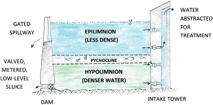
Figure 1.
Schematic profile of a density-stratified reservoir.
The upper part of the reservoir is the
Interestingly, the pycnocline is a region that often sees a high concentration of plankton. Harder [1] has observed that plankton, originally homogeneously distributed throughout a volume containing two bodies of water of different densities, will tend to congregate at the density interface, i.e. the pycnocline. Fish are there, too, to feed on the plankton.
2.2 Causes
Density stratification is often a natural phenomenon, due to:
Solar warming of the epilimnion, rendering it less dense (except at near-freezing temperatures);
Tributary inflows of cooler water from upstream, which upon entering the reservoir plunge to join the hypolimnion;
Salinity intrusion from downstream, if the dam is separating the reservoir from the sea or a saline estuary.
2.3 Problems caused by density stratification
In turn, density stratification inhibits vertical mixing, especially across the pycnocline. Impaired vertical mixing leads to the reduction of dissolved oxygen in the hypolimnion. The (impaired) downward diffusion of oxygen through the pycnocline may be estimated as follows: assume the diffusive flux to be F = −Kdc/dy, where K is the vertical diffusion coefficient and dc/dy is the vertical gradient of dissolved oxygen concentration. While in general K is a function of vertical gradients in ambient velocity as well as density gradients, Koh and Fan [2] showed that, as a rough approximation in the ocean, K can be related to the vertical density gradient alone:
where e = (1/ρ)(dρ/dy) is the vertical relative density gradient expressed in m−1, and K is expressed in cm2/s; and where 4 × 10⁻⁷ m−1 ≤ e ≤ 10−2 m−1.
Low DO leads, in turn, to problems such as the release of phosphorus from sediments, which in turn enables algae blooms on the surface. In extreme cases, the reduction in dissolved oxygen results in fish kills, unpleasant odors, and even downright dangerous hydrogen sulfide (H2S) concentrations onshore near the reservoir, and unattractive quality if hypolimnion water is withdrawn for production. This issue is discussed further by Thomann and Mueller [3], among others.
3. Management measures
3.1 Selective withdrawal, selective abstraction
A reservoir should be able to spill downstream, and not just from a surface spillway. Water for use should be withdrawn, and not just from the reservoir bottom.
If a reservoir is stratified, the poorer quality water is usually (but not always) found in the lower layers.
Figure 2(a) illustrates a discharge strong enough to overcome buoyancy forces both in the hypolimnion and in the pycnocline. The flow pattern approaches that of potential flow in a homogeneous medium. Water from below and above the outlet elevation, perhaps even epilimnion water, is withdrawn. This arrangement is partially satisfactory in the example of Reservoirs C and E, described below, and would greatly improve the product of Reservoir D.
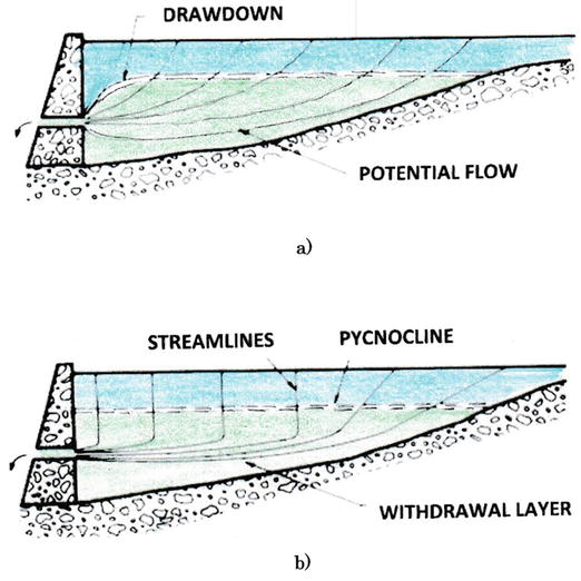
Figure 2.
Withdrawal flow patterns. From Imberger, in Fischer et al. [
Figure 2(b) illustrates a condition in which withdrawal is exclusively from the hypolimnion, without greatly disturbing the pycnocline. The withdrawal through an outlet port is kept sufficiently small that it “sips” water from a thin layer at the outlet level, somewhat like extracting very few paper sheets from the middle of a stack of papers. The water removed is replaced by the waters above, from the surface down through the epilimnion and the pycnocline to the withdrawal level, descending nearly as a block (except as disturbed by wind or inflows).
Selective withdrawal is discussed in more detail by Imberger in Chapter 6 of Fischer et al. [4], and by Bryant and Wood [5], among others.
3.2 Examples
As will be discussed below, this reservoir also has an aeration system working in tandem with the withdrawal tower, to keep the lower layers sufficiently aerobic [6].
Expensive and somewhat problematic large-scale dosing of CuSO4 has been undertaken to control the algal growths. Also, major efforts are undertaken to control the inflow to the reservoir of raw sewage and its oxygen-demanding constituents by upgrading sewerage and treatment in bordering slum areas [7, 8].
The low-level sluice is equipped with a valve, a venturi flow gauge, and a salinometer. Whenever the salinity reading exceeds that suitable for potable water, and there is a net pressure gradient in the sluice towards the sea, the valve can be carefully opened to release the impounded saline water to sea.
This arrangement permits a new impoundment to be converted from seawater to potable freshwater within a time period depending on the rate of freshwater inflow and the volume of the reservoir, without the need to first pump the impoundment dry of its original seawater. At Lower Seletar Reservoir in Singapore, the conversion took about 1 year to accomplish (Figure 3) [9].
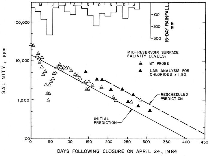
Figure 3.
Measured and predicted rate of desalination in Reservoir E.
3.3 Air-bubble mixing and hypolimnetic oxygenation
A mechanism not directly connected to the dam but often operated in association with withdrawal strategies is air-bubble induced circulation. A relatively simple system consisting of air blowers/compressors on shore, an air-feed tube leading from the blowers to a local deep spot on the lake bed, and an air diffuser at that spot on the lake bed, provide a means both to enhance mixing of epilimnion and hypolimnion waters through the pycnocline and to oxygenate the hypolimnion (Figure 4).
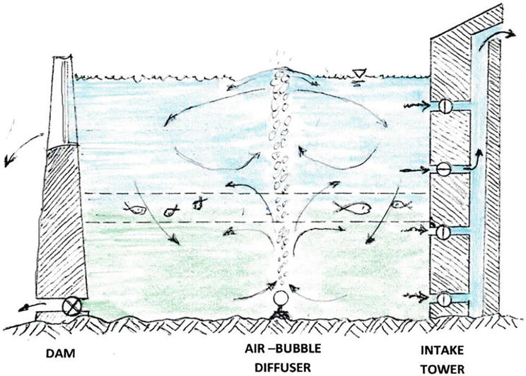
Figure 4.
Air bubble column from air diffuser on lake bed, inducing water circulation patterns.
In 1970 Cederwall and Ditmars [10] undertook an early study of the mixing of a water body by an air-bubble plume. In 2012 Lima Neto [11] modeled the liquid volume flux in bubbly jets using a simple integral approach. An extensive discussion of air-bubble columns, hypolimnetic oxygenation, and the air flow rates in many actual installations is provided by Cooke et al. [12].
3.4 Examples
However, plans to build a new and better dam led to fears that the density difference would be weakened, allowing more frequent occasions of hypolimnion water reaching the surface and causing widespread nuisance and perhaps even dangerous H2S conditions in the heart of the city. A means was sought to eliminate the H2S from the lower layer.
Following a successful test, a set of six air-bubble diffusers was deployed over a 3-km length of the Basin. A bed of crushed stone supports each diffuser assembly consisting of a fiberglass cradle and an adjustable rack. The rack holds the diffuser in place and is so constructed that it can be adjusted vertically by about 1 m to provide equal air distribution along the entire length of the diffuser. The diffuser is the 5-m long end of the 75-mm diameter polyethylene pipe from shore. It has four rows of 3-mm diameter holes placed at quarter points around the diffuser pipe’s circumference. The holes are spaced 50 mm in the center, and each row is aligned off-center to its adjacent row. A reverse flow check valve is at the intake end of the diffuser and a cleanout flange is provided at the other, normally closed, end. The airflow rate to each of the diffusers is of the order of 0.14 standard m3/s.
This diffuser system did not fully mix the very strongly stratified upper and lower layers, but it did largely eliminate the H2S and replace it with some dissolved oxygen [6, 13, 14, 15].
Based on this success, similar aerators were installed in other reservoirs in the neighborhood, and have been operating there for nearly four decades [6].
4. Impacts upstream and downstream of a dam
Large dam projects are often planned and debated for a number of years before being built, in order to optimize their benefits and to minimize their adverse impacts; yet some less desirable results still ensue. Obeng [16] describes four large dam projects in Africa. Lake Kariba was formed by damming the Zambezi River in 1958. Although hydroelectric power was realized and fish grew abundantly in the reservoir, there were problems including population resettlement, deoxygenation, seismic tremors, an explosive bloom of
Kainji Dam on the Niger River in Nigeria was intended for hydroelectric power, flood control, navigation, irrigation, and fisheries [16]. It has met many of these objectives; advance planning has helped to mitigate, although not entirely obviate adverse effects such as algal blooms and schistosomiasis.
Lake Nasser, formed by The Aswan High Dam on the Nile River in Upper Egypt formed an impoundment known as Lake Nasser in Egypt and Lake Nubia in Sudan. As intended, the dam has contained floods, produced hydroelectricity, stored water, and contributed to fisheries, but it is the adverse effects: environmental, affecting the health of the people, and threatening the limestone foundations of many of the Pharaonic monuments that have brought the most criticism of the project [6, 16].
The dam project on the Volta River in Ghana, proposed as far back as the early 1920s, was well studied and planned. However, perhaps due to pressing economic interests, the forestalling of possible environmental impacts did not receive adequate attention during construction [16]. The resettlement of some 80,000 displaced people, though well planned beforehand, was in the event rushed and poorly executed. Eventually, however, the dam fulfilled the intentions for which it was built.
For another example, in 2021 the quick filling of the reservoir behind the dam on the Blue Nile in Ethiopia has been of heated international concern to Sudan and Egypt [18]. Öziş [19] has discussed the quantity and quality implications in the upstream and downstream dimensions of damming on the Euphrates and Tigris Rivers in the Middle East. Anderson [20] discusses the impacts of the Three Gorges Dam on the Yangtze River in China.
The operators of a reservoir should anticipate a large storm inflow and may decide to draw down the reservoir to accommodate it. However, the suddenness of the drawdown can leave riparian groundwater levels unbalanced by the reservoir, to the extent that major landslides into the reservoir cannot be held back, and the suddenly displaced water overtops the dam and causes catastrophic flooding downstream. A prime example is the Vajont Dam flood near Belluno, Italy in 1963, caused by 260 million cubic meters of rock sliding abruptly into the reservoir [21].
A low coastal dam can be called a barrage. Burt & Watts [22] have edited the proceedings of an international conference held in 1996 in Cardiff, UK titled, “Barrages: Engineering Design and Environmental Impacts.” The 39 professional papers cover Concepts and Issues; Environmental Implications; Changing Estuaries; Cardiff Bay’s Hydraulic Regime; the Cardiff Bay Barrage; Ecological Issues; Water Quality; Costs, Benefits and Decisions; Tawe Barrage; River Flows and Control; and Planning and Control.
5. Conclusion
Density stratification often happens normally in a natural lake or an impoundment behind a dam, due to factors such as solar heating of the upper layers or colder or saltier water intruding the lower layers. Density stratification inhibits vertical turbulent mixing, particularly across the pycnocline, the elevation where the change in density with respect to depth is greatest.
Inhibited vertical mixing can lead to depressed dissolved oxygen levels in the hypolimnion (lower layers), particularly if the lake is subject to sewage or other oxygen-demanding inflow. Low oxygen, in turn, releases phosphorus from sediments to feed algal and other phyto-blooms on the surface.
The adverse effects of stratification can be ameliorated by the selective withdrawal of water, to waste, or to abstraction, from the upper or the lower layers, as deemed wise. Air-bubble columns have been used to reduce the intensity of stratification and to increase the oxygen level in the lower layers.
It is important to try to anticipate the possible adverse impacts that the construction of a dam, and the creation of its impoundment, may have on the affected population, environment, and geology nearby, upstream, and downstream. As discussed above, the possible impacts are many and varied. Field conditions from site to site may vary sufficiently that simple import of one solution to a problem, successful at one place, may not necessarily work well at another, as noted for Kai Tak Nullah. The best advice is to move forward slowly and carefully with implementation.
References
- 1.
Harder W. Reactions of plankton organisms to water stratification. Limnology and Oceanography. 1968; 13 (1):156-168 - 2.
Koh RCY, Fan L-N. Mathematical Models for the Prediction of Temperature Distributions Resulting from the Discharge of Heated Water into Large Bodies of Water. USEPA Water Quality Control Office Contract No. 14-12-570. Washington, D.C., USA: U.S. Government Printing Office; 1970 - 3.
Thomann RV, Mueller J. Principles of Surface Water Quality Modeling and Control. New York, NY, USA: Harper and Row; 1987 - 4.
Fischer HB et al. Mixing in Inland and Coastal Waters. New York, NY, USA: Academic Press; 1979 - 5.
Bryant PJ, Wood IR. Selective withdrawal from a layered fluid. Journal of Fluid Mechanics. 1976; 77 (3):581 - 6.
French JA. Personal Communication - 7.
French JA et al. Remediation for Guarapiranga Reservoir, Sao Paulo, Brazil. In: Fifth Stockholm Water Symposium. Abstracts. Stockholm, Sweden. 1995. p. 75 - 8.
Oliveira LHW et al. Dimensionamento de Sistema de Aeração por Circulação Artificial da Coluna d’Água para o Reservatorio Guarapiranga, em São Paulo. 19th Congresso Brasileiro de Engenharia Sanitária e Ambiental. Brasil: Foz do Iguaçu; 1996. In Portuguese - 9.
French JA, Harley BM, Neysadurai A. Desalination of an impounded estuary. In: Proc. of the 1985 Specialty Conference in Environmental Engineering. Boston, Massachusetts: ASCE; 1985 - 10.
Cederwall K, Ditmars JD. Analysis of air-bubble plumes. Rep. No. KH-R-24. W.M. Keck Laboratory of Hydraulics and Water Resources, Division of Engineering and Applied Physics, California Institute of Technology; 1970 - 11.
Neto L, Iran E. Modeling the liquid volume flux in bubbly jets using a simple integral approach. Journal of Hydraulic Engineering ASCE. 2012; 138 (2):210 - 12.
Cooke GD et al. Restoration and Management of Lakes and Reservoirs. 3rd ed. Baton Rouge, FL, USA: CRC/Taylor and Francis; 2005 - 13.
Metropolitan District Commission. Charles River Artificial Destratification Project, Boston, Massachusetts. 1981 - 14.
Science Museum of Boston. Handout: Why are Those Bubbles in the River? 1981 - 15.
Godbey A et al. An impact assessment of the new Charles River dam. Boston’s Charles River Basin: An Engineering Landmark, Journal of the Boston Society of Civil Engineers Section, ASCE. 1981; 67 (4):362-385 - 16.
Obeng L. Environmental impacts of four African impoundments. In: Gunnerson C, Kalbermatten J, editors. Environmental Impacts of International Civil Engineering Projects and Practices. ASCE Preprint 2920. Reston, VA, USA. 1977. pp. 29-43 - 17.
Matanzima J. Thayer Scudder’s four stage framework, water resources dispossession and appropriation: The Kariba case. International Journal of Water Resources Development. 2021; 38 (2):322 - 18.
Saied M. Ethiopia preps for third filling as Nile dam diplomacy fails. Al-Monitor. October 20, 2021 - 19.
Öziş Ü. Quantity/quality implications in the upstream/downstream dimensions of Euphrates & Tigris in the Middle-East. In: Fifth Stockholm Symposium. Stockholm, Sweden. 1995 - 20.
Anderson W (Schoolworkhelper Editorial Team). Impacts of Three Gorges Dam. Poster in: SchoolWorkHelper. 2019. Available from: https://schoolworkhelper.net/impacts-of-three-gorges-dam/ - 21.
Graf von Hardenberg W. Expecting Disaster: The 1963 Landslide of the Vajont Dam. Arcadia Collection of Technology and Expertise. No. 8. 2011 - 22.
Burt N, Watts J. Barrages: Engineering Design & Environmental Impacts. Chichester, UK: Wiley; 1996