Open Access is an initiative that aims to make scientific research freely available to all. To date our community has made over 100 million downloads. It’s based on principles of collaboration, unobstructed discovery, and, most importantly, scientific progression. As PhD students, we found it difficult to access the research we needed, so we decided to create a new Open Access publisher that levels the playing field for scientists across the world. How? By making research easy to access, and puts the academic needs of the researchers before the business interests of publishers.
We are a community of more than 103,000 authors and editors from 3,291 institutions spanning 160 countries, including Nobel Prize winners and some of the world’s most-cited researchers. Publishing on IntechOpen allows authors to earn citations and find new collaborators, meaning more people see your work not only from your own field of study, but from other related fields too.
To purchase hard copies of this book, please contact the representative in India:
CBS Publishers & Distributors Pvt. Ltd.
www.cbspd.com
|
customercare@cbspd.com
In image guided radiotherapy (IGRT), cone beam computed tomography (CBCT) is an important tool for patient positioning and verification before treatment. Therefore, the CBCT system has become an essential part and significant component of radiation therapy because it is a development that facilitates more accurate delivery of the prescribed dose to the treatment sites. However, the CBCT system uses ionizing radiation to acquire images for patient setup. Historically, the significance of this imaging dose has been overlooked as it is relatively small in quantity when compared to therapeutic doses used to patients for treatment purposes. In recent years, several works have been made to estimate the dose delivered from CBCT imaging using Monte Carlo simulations in phantoms and patients, thermoluminescence dosimetry (TLD) as well as a variety of other dosimetry methods. The aim of this chapter is to summarize the results from international literature concerning the additional imaging dose delivered to patients due to the usage of Cone Beam CT during radiation therapy, as well as to discuss the future work necessary in order to arrive at a clinically relevant personalized dose estimation protocol.
Faculty of Medicine, Medical Physics Department, University of Thessaly, Larisa, Greece
Foteini Simopoulou
Faculty of Medicine, Radiotherapy Department, University of Thessaly, Larisa, Greece
Vasileios Simopoulos
Faculty of Medicine, Radiotherapy Department, University of Thessaly, Larisa, Greece
George Kyrgias
Faculty of Medicine, Radiotherapy Department, University of Thessaly, Larisa, Greece
Kiki Theodorou
Faculty of Medicine, Medical Physics Department, University of Thessaly, Larisa, Greece
*Address all correspondence to: Iliopoulos_panagiotis@hotmail.com
1. Introduction
Cancer even today continues to be recognized as the most lethal among all illnesses [1]. To face cancer, various treatment approaches have been employed in recent years. Alongside surgery and chemotherapy, radiation therapy stands out as a prominent method in cancer treatment. In cases where surgery and chemotherapy are not feasible, radiation therapy becomes the sole available option for certain types of cancer. Considering the crucial role of radiation therapy in the treatment of many cancer types, the accuracy of treatment delivery becomes vital for cancer patients [2]. One of the key factors contributing to the effectiveness of cancer treatment lies in appropriately irradiating the targeted tumor tissue while protecting the surrounding normal tissues as much as possible. Therefore, ensuring proper patient positioning before and during treatment is essential for optimal outcomes [3].
Image guided radiotherapy (IGRT) is an innovative radiation treatment technique that incorporate the use of image guidance which improves the outcome of treatment by delivering the radiation therapy with greater precision to the planned target [4].
In the last decades, patient positioning in radiotherapy relied on the megavoltage (MV) treatment beam and tools like an electronic portal imaging device (EPID) or film positioned behind the patient. However, because of the poor soft-tissue contrast due to Compton scattering a new technique was invested kilovoltage- cone beam computed tomography (kV-CBCT) [5].
Nowadays, the Varian on-board imaging (OBI) and Elekta X-ray volume (XVI) systems are frequently used for kV-CBCT scans during radiotherapy treatment [6]. CBCT has become the most used imaging modality for IGRT and its significance lies in its ability to generate high-resolution volumetric images of patient’s anatomy during radiotherapy enhancing the treatment’s effectiveness. However, there are concerns regarding the additional radiation dose associated with daily imaging techniques like CBCT [7].
In the past, there was an assumption that imaging doses were insignificant compared to therapeutic doses, leading to less emphasis on reducing them. However, recent changes in imaging practices, involving more frequent exposures, have the potential to accumulate hundreds of mGy doses in patient tissues [8, 9, 10]. Unlike diagnostic radiology where imaging settings are often adjusted and optimized for individual patients, this is typically not the case in the context of radiotherapy, where imaging settings remain unchanged and are not fitted to each patient’s specific needs [11].
This additional imaging dose delivered to patients from CBCT has become an issue of concern that warrants big attention, so Monte Carlo simulations, Thermoluminescence dosimetry (TLD), and a variety of other dosimetry methods are used to estimate these doses.
The purpose of this chapter is to offer a comprehensive review on imaging dose during IGRT which will provide Medical Physicists and Doctors of a Radiotherapy Department the necessary evidence-based knowledge to plan and execute, in the most effective and safe way, their IGRT treatment.
Cone beam computed tomography (CBCT), is an advanced medical imaging method that utilizes kV X-rays with high contrast. Unlike traditional computed tomography (CT), CBCT uses divergent X-rays, creating a cone-shaped beam. Practically a kV source and a flat panel imager are mounted onto the linear accelerator (LINAC) gantry in a way that they both share a common isocenter with the treatment unit [12].
CBCT plays a pivotal role in modern radiotherapy, serving as a valuable imaging modality for treatment planning and delivery. It provides volumetric images of the patient’s anatomy with high resolution, allowing for precise localization of the target area and accurate dose calculation. CBCT offers advantages over conventional imaging techniques, such as the ability to capture three-dimensional images in a single rotation of the gantry and the capacity to monitor anatomical changes during the course of treatment. By integrating CBCT into treatment workflow, radiation physicists and oncologists can optimize treatment plans, ensure proper patient positioning, and make necessary adjustments based on real-time imaging data.
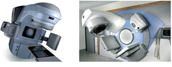
Currently, there are two gantry-mounted cone beam devices. These include the Varian on Board Imager (OBI) from Varian Medical Systems, USA, and the Elekta X-ray volume imaging (XVI) from Elekta Oncology Systems, UK (Figure 1). These two systems utilize kV CBCT imaging technology and operating within the range of 30–140 kV. A kV X-ray source (kVS) and a kV detector (kVD) are attached to the linac gantry at a 900 offset from the treatment beam.
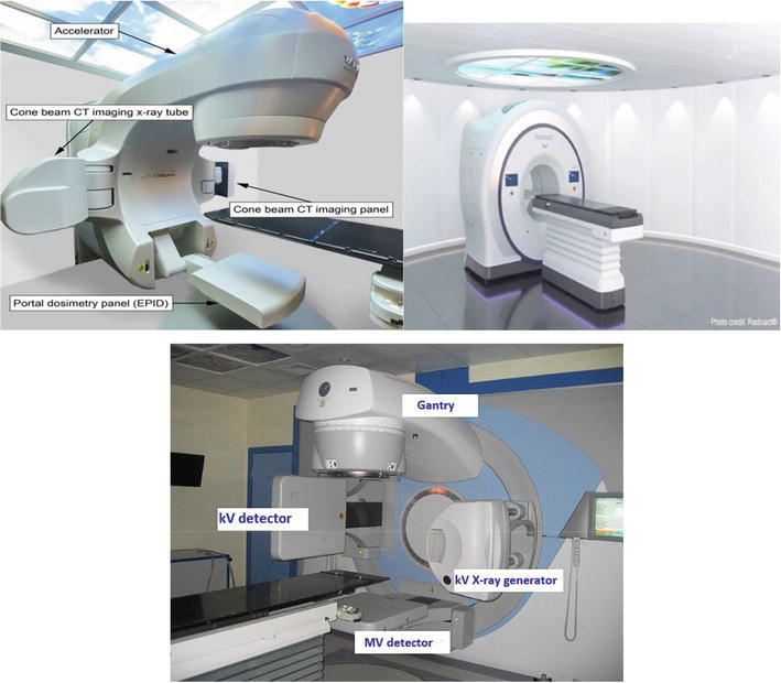
Megavoltage imaging techniques capture projection images using either electronic portal imaging devices (EPIDs) or, in the case of MVCT in the tomotherapy [13, 14], a single-row CT detector (Figure 2). For the EPID technique an AP (anterior/posterior) image is mainly used for 2D positioning and for 3D positioning two perpendicular images AP and lateral are used [15]. Mega voltage CT collects complete 3D images during its 360-degree rotation around the patient [15]. The volumetric MV-CBCT images are reconstructed using EPID projections, leading to a higher dose compared to a pair of orthogonal MV portal images [16]. The imaging dose from a 2.5-MV image (Tomotherapy systems) beam is approximately half that of a 6-MV beam.
KV-CBCT images produce enhanced high-contrast resolution compared to MV-CBCT images. The enhancement in image quality is ascribed to the prevalence of the photoelectric effect at kV energies. On the other hand, at MV energies, the dominant interaction is Compton scattering, which is inversely proportional to photon energy and remains relatively unaffected by the atomic number (Z) of the material. Consequently, the image contrast of MV-CBCT images is reduced for various tissue-equivalent materials [12]. Since the majority of clinical systems use kV CBCT, in the following we will address issues concerning those systems.
The primary utilization of CBCT on linear accelerators (Linacs) is for IGRT but also its capabilities extend to adaptive radiotherapy as well. Highly conformal treatment techniques like intensity modulated radiotherapy (IMRT), volumetric modulated arc therapy (VMAT), and 3D-conformal radiation therapy (3DCRT) necessitate accurate localization of the target and organs at risk. CBCT serves as an advanced imaging modality enabling radiation therapists to correct for target position changes before treatment and monitor complex alterations in patient and tumor anatomy such as weight loss and tumor regression. The advancements in large-area flat-panel detectors and computing capacity have made CBCT the preferred platform for precise three-dimensional IGRT tasks [17]. As a result, it has started replacing two-dimensional IGRT to verify if the tumor region remains within the planning target volume (PTV) throughout treatment. CBCT as an IGRT modality has gained popularity for patient setup verification and tumor position confirmation [18] and also the use of CBCT-based IGRT has notably enhanced treatment across various sites [19, 20, 21].
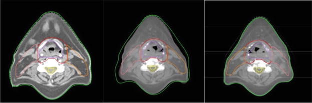
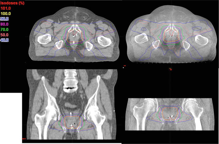
The accuracy of delivering the prescribed dose throughout a treatment course using a single reference, known as planning CT (PCT), can be limited by variations in the patient’s anatomy, such as weight loss and changes in the size and position of the tumor. Therefore, having information about the patient and tumor anatomy immediately before each treatment fraction becomes crucial for improving treatment outcomes. Adaptive radiotherapy (ART) is a technique that involves modifying treatment parameters, such as field margins and the number of fractions, based on changes observed in both tumor anatomy and patient anatomy. CBCT has the potential to be a valuable tool for online ART [22] because it helps to localize the tumor position in three dimension and detects any changes in tumor or patient anatomy during treatment. This is achieved by fusing CBCT images with PCT images using image registration algorithms and assessing the differences (Figures 3 and 4). In cases where it is deemed necessary, the dose distribution can be reevaluated using the treatment planning system (TPS) or specialized software integrated into the imaging system. This allows for the generation of optimized treatment plans by incorporating the information obtained from CBCT scans and adapting the dose delivery accordingly [12].
Figure 3.
The PTV and organ outlines were duplicated from the initial CT image (a) to the CBCT image (b) acquired two weeks after treatment. As needed, adjustments were made (c). It is essential to observe the notable alterations in the skin and PTV contours during this process.
Figure 4.
The dose distributions were computed for the identical prostate IMRT treatment plan using two different imaging sources: The planning CT on the left and a CBCT acquired on the first day of treatment on the right [22].
For CBCT measurements mainly thermoluminescent dosimeter (TLDs) and Monte Carlo codes were used but there are also other detectors such as metal-oxide-semiconductor field effect transistor (MOSFET), ion chamber, radiographic and radio chromic film, optically stimulated luminescence dosimeter (OSLD), and glass dosimeter [8] that have been used, according to literature, for CBCT dose estimation.
Ionization chambers, specifically Farmer-type chambers, are the primary detectors employed for reference dosimetry in clinical settings. These chambers have a small energy dependence across a range of diagnostic and therapeutic energy levels [21]. However, the response of an ionization chamber can be influenced by various factors. These include air density, exposure rate, ion recombination losses, and electric field polarity, all of which impact the collection rate of ion pairs [22]. Reference dosimetry protocols take these factors into consideration to ensure accurate measurements [23].
The American Association of Physicists in Medicine (AAPM) has established a set of guidelines for accurately measuring the reference dosimetry of kilovoltage (kV) energy X-rays [24]. The method involves determining the absorbed dose to water at a depth of 2 cm in a water phantom, and it is calculated using the following formula:
Dw=MplNkPQ,chamberPsheathμenρwairwaterE1
Where:
Dwrepresents the absorbed dose to water (Gy),
Mpl is the chamber reading, which is corrected for various factors such as ion recombination, polarity, temperature, pressure, and electrometer response (nC),
Nkis the air-kerma calibration factor, adjusted based on the spectrum of the X-ray beam used (mGy/nC),
PQ,chamberis the chamber correction factor, accounting for the individual response of the specific chamber used for measurement,
Psheathis a factor related to the sheath used with the chamber,
μenρwairwaterrepresent the mass energy-absorption coefficients of air and water, respectively [24]. By adhering to this protocol and using the provided lookup tables, accurate reference dosimetry measurements can be obtained for kilovoltage X-ray energies in the specified range.
Several studies have been published regarding the application of optically stimulated luminescence dosimeters (OSL) in medical settings, specifically for therapeutic radiotherapy beams [25, 26, 27, 28, 29, 30] and low energy X-rays [31, 32]. The most used OSL dosimetry system consisting of a small reader (microStar) and a detector (nanodot) [33].
The film dosimetry system uses Gafchromic XR-QA2 from International Specialty Products in Wayne, NJ. To scan the films, an Epson Expression 10000XL flat-bed document Scanner is employed by Seiko Epson Corporation in Nagano, Japan. The Gafchromic XR_QA2 film is specifically designed as a quality assurance tool for radiology and dosimetry applications [34].
Thermoluminescent dosimeters (TLDs) are crystalline materials commonly used for radiation dosimetry purposes. Lithium fluoride TLDSs (TLD 100-LiF) are mainly used for dosimetry measurements. To ensure greater accuracy, each TLD is individually calibrated prior to the measurements for certain the photons energy and are irradiated in a poly-methyl methacrylate holder. Subsequently, the irradiated TLDs are read using a Harsaw 3500 TLD reader (Harsaw Thermo Electron, Solo, USA) [3].
The Monte Carlo (MC) method is the gold standard for simulating the tracking of particles and the deposition of radiation doses across various energy ranges relevant to therapeutic and imaging applications. In the context of dose calculations for CBCT imaging, the EGSnrc code system, which consists of the BEAMnrc and DOSXYZnrc codes has been extensively utilized. Additionally, other general purpose MC codes like MCNP and Geant4 have also been employed in this field [8, 35, 36, 37, 38, 39, 40, 41, 42, 43, 44, 45, 46, 47, 48, 49, 50, 51, 52].
Dose measurements from CBCT were divided into two categories: in vitro and in vivo measurements.
In vitro measurements in the context of radiotherapy CBCT refer to experimental evaluations conducted outside of a patient’s body to assess doses. A significant portion of research on measuring doses from CBCT imaging has been conducted using phantoms [6, 18, 19, 20, 21, 22, 23, 24, 25, 26, 27, 28, 29, 30, 31, 32, 33, 34, 35, 36, 37, 38, 39, 40, 41, 42, 43, 44]. The findings demonstrate the wide of doses observed, influenced by various factors such as imaging protocols, phantom characteristics, and dosimeter selection. Understanding these dose distributions is crucial for optimizing imaging protocols, managing patient radiation exposure and ensuring safe and effective radiotherapy treatments [8].
Also, for calculating in vitro patient-specific imaging doses, Monte Carlo code is used and relies on CT images of the unique characteristics of the patient’s anatomy. The most precise approach for computing patient dose from diagnostic energy X-rays is through the utilization of the Monte Carlo technique. First, the real X-ray source must be modeled. Using various Monte Carlo codes such as BEAM or GATE, our source is modeled. Therefore, the code must be validated through various procedures such as the PDDs and the profiles, and after the identification of the measurements and the Monte Carlo calculated data, our code is validated [36]. The final step is to calculate patient doses with the validated Monte Carlo code using real patient CT images and evaluate the calculated doses (Figure 5).
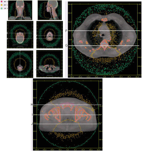
Figure 5.
Monte Carlo isodose lines on reconstructed CBCT image slices for head and neck cancer, lung cancer, and pelvis patient cancer [36].
4.1 In vivo studies
To assess the doses received by patients during medical procedures, in vivo measurements can be conducted using available detectors such as diodes, thermoluminescent dosimeters (TLDs), or optically stimulated luminescent dosimeters (OSLDs) [23, 29, 30]. It is important to note that dosimeters designed for in vivo measurements in megavoltage (MV) beams, like diodes, are not suitable for kilovoltage (kV) beams due to the inherent buildup and the significant difference to kV radiation response [51]. In general, patients are typically examined to assess skin dose [52, 53, 54, 55, 56]. However, there have been a couple of studies that focused on measuring the dose inside the rectum [57, 58]. The skin dose measurements vary from a fraction of a cGy (for low-dose head and neck imaging) to 7 cGy (for high-dose pelvic imaging), and these measurements depend on the location of measurement, the technique employed, and the patient’s size. For the common clinical practice of pelvic imaging using the Elekta system, the rectal dose measurements indicate an average dose of 2–3 cGy to the rectum per CBCT acquisition.
4.2 CBCT doses for different sites
It is crucial to examine the patient doses resulting from CBCT imaging. In kilovoltage imaging, lower dose values are typically observed in head and neck imaging protocols that employ lower time current products (mAs) and partial arc image acquisition. On the other hand, higher doses are found in trunk imaging with higher mAs values and full 360° image acquisition. Megavoltage CBCT imaging results in higher doses compared to kilovoltage imaging, the dose directly correlated to the imaging protocol, specifically the monitor unit (MU) setting used. It is worth noting that kilovoltage doses exhibit greater heterogeneity, typically reaching their maximum value on the skin and showing increased absorption in bone due to the prominence of the photoelectric effect [8].
Table 1 summarizes the results of those studies, encompassing the measured organ doses which range from 0.03 to some mGy per acquisition.
The variation in doses can be attributed to multiple factors, including the type and size of the phantom, the location of the measurement within the phantom, the specific imaging techniques employed, and the characteristics of the imaging devices. Assigning a single value to represent the dose magnitude based on the imaged anatomy is challenging due to the wide range of experimental setups and variables involved [8].
More specifically Table 2 shows a comprehensive list of organ doses for different sites.
To assess the imaging dose and its biological effect, the equivalent doses to the organs and the effective dose are calculated for each patient during CBCT acquisition. The equivalent doses to specific organs are determined by utilizing the corresponding mean doses and radiation weighting factors. The effective dose, E, is calculated using the equation:
E=∑TWT∑RWRDT,RE2
Where WΤrepresents the weighting factor of tissue, WR represents the radiation weighting factor and DT,R represents the mean absorbed dose to tissue T. The weighting factors are based on publication 103 of the International Commission on Radiological Protection (ICRP) [58, 59].
The AAPM Task Group 75 [15] report emphasized the importance of using effective dose as a metric to evaluate patient exposure to imaging doses. Several studies have reported on the effective doses derived from kilovoltage CBCT utilized anthropomorphic phantoms to measure absorbed does, which were then concerted to effective doses using tissue factors from ICRP report 103. The reported effective dose values for trunk imaging ranged from 1.1 to 24 mSv, while for head and neck imaging, the range was 0.09–9.4 mSv per fraction as you can see in Table 3.
The wide variation in reported effective dose values can be attributed to factors such as the same anatomical site being imaged, the measured dose, the specific tissue weighting factors used, the imaging protocol (low dose vs. standard dose), and the imager which determines the imaged volume and the use of a bowtie filter.
Typically, when employing low-dose imaging protocols for head and neck imaging, the resulting effective doses are below 2 mSv. On the other hand, standard imaging protocols have been reported to result in effective doses of up to 24 mSv [8].
To ensure the appropriate dose administration and consistency in medical imaging, it is important to conduct various checks.
To verify the expected imaging dose for each image acquisition procedure which involves a specific protocol the measurement can be conducted in air or within a phantom, as per the guidelines set by the AAPM. To ensure adherence to manufacturer specifications, dosimetry protocols are implemented for kV beams. These protocols are designed to verify that the measured dose falls within the range stated by the manufacturer. The process of acquiring images should encompass the utilization of a specific device. It is important to ensure that the procedures for image acquisition incorporate both the necessary steps. The beam energy should be adjusted to suit the specific application. It is crucial that the energy used is suitable for the desired outcome. In order to ensure that X-ray scattering is fully captured, it is necessary for the sizes to be sufficiently large [16].
It is recommended to utilize the recommendations outlined in AAPM quality assurance reports, including those from AAPM Task Group 142 [63]. Regular consistency checks should be performed annually and after any system upgrades. Moreover, commercially available tools designed for monitoring beam parameters (such as kVp, mAs, etc.) specific to the process can be employed to conduct air-based assessments for imaging dose consistency.
Imaging dose reduction is very important and ALARA should be always the most significant principle in practice. As advised by AAPM TG-75 [15] and AAPM TG-179 [63] a, numerous techniques are available to lower the imaging dose to organs at risk [16].
Minimize the size of the imaging field as much as you can. By doing so, the amount of tissue exposed to radiation around the desired area will decrease. Additionally, reducing the top-to-bottom range of kV-CBCT scans can considerably lessen both the overall and scattered radiation dose within the region [64].
Improve the imaging parameters such as kilovolt peak (kVp) and milliampere-seconds (mAs), and choose suitable default clinical protocols provided by the manufacturer for various body areas in typical adult patients (such as pelvis, abdomen, thorax, head, and neck.
Utilizing partial rotation in kV-CBCT scan protocols offers the advantage of selectively minimizing radiation exposure to superficial organs. By employing partial rotation during a head scan, the dose to the eyes (64) can be significantly reduced. This technique can also be applied to decrease the dose to the bladder or rectum during kV-CBCT scans.
Take into account the incorporation of complete bow tie filters during the acquisition of planar kV images. These filters have the capability to substantially decrease both the dose to the skin and the dose to vulnerable organs. It is essential to consistently employ the appropriate bow tie filter for kV-CBCT acquisition, particularly when manual placement of the filter is necessary. Failing to use the filter can lead to an imaging dose increase of 2–4 times [16, 50].
CBCT has evolved into a conventional imaging method used for patient positioning during radiation therapy. In the past, the imaging dose from CBCT was often disregarded due to its perceived insignificance compared to the therapeutic dose used for treatment. However, the frequent use of CBCT has prompted a reevaluation of the need to measure, document, and account for the imaging dose. This becomes a concern when the imaging dose is substantial compared with the therapeutic dose. In this chapter, the focus is on the attempts to measure and compute the extra dose from CBCT and its potential effects on the total radiation therapy treatment dose [8].
Manufacturers have made improvements in reducing the imaging dose of CBCT units over time, with advancements in technology, modern CBCT systems typically administer lower doses than their older counterparts. Present-day CBCT systems implement diverse techniques, including collimator cassettes and field size-defining blades, to restrict the range of the X-ray beam, which affects the scan volume and the dose to healthy tissues. The use of bowtie filters also influences beam quality and can result in lower skin doses. Additionally, post-processing techniques are often employed to achieve acceptable image quality with lower doses. The magnitude of the dose from CBCT is directly related to the current-time product used in the image acquisition protocol, which can be preset or adjusted by the user. The patient’s size, particularly indicated by body mass index (BMI), has a significant impact on the dose delivered at depth, especially for kilovoltage beams. It is noteworthy that CBCT systems typically lack automatic exposure control (AEC) adjustment, a feature commonly found in diagnostic imaging units. However, integrating AEC into CBCT systems would be beneficial in reducing the imaging dose. Additionally, users can employ various techniques to minimize the imaging dose, such as adjusting the start/stop angles of the X-ray source to avoid sensitive organs, using smaller cassettes or field sizes to shorten the scan length, and implementing low-dose protocols to obtain acceptable images [8].
If a protocol with a high dosage is consistently used, the cumulative imaging dose delivered over the course of treatment can be equivalent to a single fraction of the therapeutic dose. In such cases, incorporating the imaging dose into the treatment planning process may be essential. Research indicates that including the imaging dose during plan, optimization can result in a decrease in the total dose delivered to the patient. Nevertheless, this undertaking is difficult and necessitates either employing Monte Carlo simulations or commissioning imaging beams in treatment planning systems. Presently, commercially available systems lack the capacity to calculate the dose from kilovoltage imaging beams. Therefore, it is important to implement the ability to account for imaging dose in commercial treatment planning systems to enable comprehensive dose optimization [65, 66, 67].
If the cumulative dose from repeated imaging procedures is anticipated to exceed 5% of the prescribed target dose, it is advisable to incorporate the imaging dose into the overall dose during the treatment planning phase. Estimating patient organ doses can be achieved through patient-specific or non-patient-specific methods. To enable patient-specific imaging dose calculations, it might be necessary to introduce new algorithms for kV beams into commercially available treatment planning systems [62].
As the imaging dose typically constitutes only a small portion of the prescribed target dose, it is deemed acceptable for the uncertainties in calculated imaging doses to fall within 20%. Despite this level of uncertainty, the overall combined dose (therapeutic + imaging) is expected to remain within a range of 2–3% [62].
This chapter highlights the increasing awareness and interest in evaluating the additional dose from CBCT. As image guidance plays a vital role in radiation therapy treatment, and with the possibility of treatment adaptation based on dose recalculation in the patient’s actual treatment position, it is crucial to implement tools for controlling and managing the potential negative effects of the extra dose arising from on-board imaging devices.
In the future, there should be some protocol according to which it will be practically possible to be able to calculate for each patient their imaging dose from the CBCT so that there is an individualized integrated view of the total dose (treatment and imaging) of the patient.
1.Stewart BW, Wild C. International Agency for Research on Cancer. World Cancer Report. France: Lyon CEDEX; 2014. p. 2014
2.Xu XG, Bednarz B, Paganetti H. A review of dosimetry studies on external-beam radiation treatment with respect to second cancer induction. Physics in Medicine and Biology. 2008;53(13):R193
3.Özseven A, Dirican B. Evaluation of patient organ doses from kilovoltage cone-beam CT imaging in radiation therapy. Reports of Practical Oncology and Radiotherapy. 2021;26(2):251-258
4.Son K, Kim JS, Lee H, Cho S. Imaging dose of human organs from kV-CBCT in image-guided radiation therapy. Radiation Protection Dosimetry. 2017;175(2):194-200
5.Buckley JG, Wilkinson D, Malaroda A, Metcalfe P. Investigation of the radiation dose from cone-beam CT for image-guided radiotherapy: A comparison of methodologies. Journal of Applied Clinical Medical Physics. 2018;19(1):174-183
6.Abuhaimed A, Martin CJ. Assessment of organ and size-specific effective doses from cone beam CT (CBCT) in image-guided radiotherapy (IGRT) based on body mass index (BMI). Radiation Physics and Chemistry. 2023;208:110889
7.Cumur C, Fujibuchi T, Hamada K. Dose estimation for cone-beam computed tomography in image-guided radiation therapy using mesh-type reference computational phantoms and assuming head and neck cancer. Journal of Radiological Protection. 2022;42(2):021533
8.Alaei P, Spezi E. Imaging dose from cone beam computed tomography in radiation therapy. Physica Medica. 2015;31(7):647-658
9.Zhou L, Bai S, Zhang Y, Ming X, Deng J. Imaging dose and cancer risk in image guided radiation therapy of cancers. International Journal of Radiation Oncology Biology Physics. 2015;93(3):S181-S182
10.Deng J, Zhang Y, Zhou L, Ming X, Wu H. Why are we concerned about imaging dose in the radiotherapy of cancers? Austin Journal of Radiology. 2014;1:1-3
11.Martin C, Kron T, Vassileva J, Wood T, Joyce C, Ung N, et al. An international survey of imaging practices in radiotherapy. Physica Medica. 2021;90:53-65
12.Srinivasan K, Mohammadi M, Shepherd J. Applications of linac-mounted kilovoltage cone-beam computed tomography in modern radiation therapy: A review. Polish Journal of Radiology. 2014;79:181
13.Mackie TR, Kapatoes J, Ruchala K, Lu W, Wu C, Olivera G, et al. Image guidance for precise conformal radiotherapy. International Journal of Radiation Oncology Biology Physics. 2003;56(1):89-105
14.Mackie TR, Balog J, Ruchala K, Shepard D, Aldridge S, Fitchard E, et al. Tomotherapy. Seminars Radiation Oncology. Jan 1999;9(1):108-117
15.Murphy MJ, Balter J, Balter S, BenComo JA Jr, Das IJ, Jiang SB, et al. The management of imaging dose during image-guided radiotherapy: Report of the AAPM task group 75. Medical Physics. 2007;34(10):4041-4063
16.Ding GX, Alaei P, Curran B, Flynn R, Gossman M, Mackie TR, et al. Image guidance doses delivered during radiotherapy: Quantification, management, and reduction: Report of the AAPM therapy physics committee task group 180. Medical Physics. 2018;45(5):e84-e99
17.Jaffray DA, Siewerdsen JH, Wong JW, Martinez AA. Flat-panel cone-beam computed tomography for image-guided radiation therapy. International Journal of Radiation Oncology Biology Physics. 2002;53(5):1337-1349
18.Moore CJ, Amer A, Marchant T, Sykes JR, Davies J, Stratford J, et al. Developments in and experience of kilovoltage X-ray cone beam image-guided radiotherapy. The British Journal of Radiology. 2006;79(special_issue_1):S66-S78
19.Oldham M, Létourneau D, Watt L, Hugo G, Yan D, Lockman D, et al. Cone-beam-CT guided radiation therapy: A model for on-line application. Radiotherapy and Oncology. 2005;75(3):271-2E1
20.Guckenberger M, Meyer J, Wilbert J, Baier K, Sauer O, Flentje M. Precision of image-guided radiotherapy (IGRT) in six degrees of freedom and limitations in clinical practice. Strahlentherapie und Onkologie. Jun 2007;183(6):307-313
21.Boda-Heggemann J, Lohr F, Wenz F, Flentje M, Guckenberger M. kV-Cone-beam-CT-basierte bildgeführte Strahlentherapie–ein klinischer Überblick: A Clinical Review. Strahlentherapie und Onkologie. 2011;187:284-291
22.Ding GX, Duggan DM, Coffey CW, Deeley M, Hallahan DE, Cmelak A, et al. A study on adaptive IMRT treatment planning using kV cone-beam CT. Radiotherapy and Oncology. 2007;85(1):116-125
23.Gilling L. A GATE Monte Carlo Dose Analysis from Varian XI Cone-beam Computed Tomography. University of Canterbury; 2019
24.Ma CM. AAPM TG-61 report on kilovoltage X-ray dosimetry: Formalisms and applications. In: Proceedings of the 22nd Annual International Conference of the IEEE Engineering in Medicine and Biology Society (Cat. No.00CH37143), Chicago, IL, USA. 2000. Vol. 3. pp. 2308-2312. DOI: 10.1109/IEMBS.2000.900604
25.Schembri V, Heijmen B. Optically stimulated luminescence (OSL) of carbon-doped aluminum oxide for film dosimetry in radiotherapy. Medical Physics. 2007;34(6Part1):2113-2118
26.Jursinic PA. Characterization of optically stimulated luminescent dosimeters, OSLDs, for clinical dosimetric measurements. Medical Physics. 2007;34(12):4594-4604
27.Yukihara E, McKeever S. Optically stimulated luminescence (OSL) dosimetry in medicine. Physics in Medicine and Biology. 2008;53(20):R351
28.Jursinic PA. Changes in optically stimulated luminescent dosimeter (OSLD) dosimetric characteristics with accumulated dose. Medical Physics. 2010;37(1):132-140
29.Mrčela I, Bokulić T, Izewska J, Budanec M, Fröbe A, Kusić Z. Optically stimulated luminescence in vivo dosimetry for radiotherapy: Physical characterization and clinical measurements in 60Co beams. Physics in Medicine and Biology. 2011;56(18):6065
30.Reft CS. The energy dependence and dose response of a commercial optically stimulated luminescent detector for kilovoltage photon, megavoltage photon, and electron, proton, and carbon beams. Medical Physics. 2009;36(5):1690-1699
31.Al-Senan RM, Hatab MR. Characteristics of an OSLD in the diagnostic energy range. Medical Physics. 2011;38(7):4396-4405
32.Ding GX, Malcolm AW. An optically stimulated luminescence dosimeter for measuring patient exposure from imaging guidance procedures. Physics in Medicine and Biology. 2013;58(17):5885
33.Mail N, Yusuf M, Alothmany N, Kinsara AA, Abdulkhaliq F, Ghamdi SM, et al. A methodology for on-board CBCT imaging dose using optically stimulated luminescence detectors. Journal of Applied Clinical Medical Physics. 2016;17(5):482-499
34.Giaddui T, Cui Y, Galvin J, Yu Y, Xiao Y. Comparative dose evaluations between XVI and OBI cone beam CT systems using Gafchromic XRQA2 film and nanoDot optical stimulated luminescence dosimeters. Medical Physics. 2013;40(6Part1):062102
35.Ding GX, Coffey CW. Beam characteristics and radiation output of a kilovoltage cone-beam CT. Physics in Medicine and Biology. 2010;55(17):5231
36.Ding GX, Duggan DM, Coffey CW. Accurate patient dosimetry of kilovoltage cone-beam CT in radiation therapy. Medical Physics. 2008;35(3):1135-1144
37.Spezi E, Downes P, Radu E, Jarvis R. Monte Carlo simulation of an x-ray volume imaging cone beam CT unit. Medical Physics. 2009;36(1):127-136
38.Downes P, Jarvis R, Radu E, Kawrakow I, Spezi E. Monte Carlo simulation and patient dosimetry for a kilovoltage cone-beam CT unit. Medical Physics. 2009;36(9Part1):4156-4167
39.Chow JC, Leung MK, Islam MK, Norrlinger BD, Jaffray DA. Evaluation of the effect of patient dose from cone beam computed tomography on prostate IMRT using Monte Carlo simulation. Medical Physics. 2008;35(1):52-60
40.Deng J, Chen Z, Roberts KB, Nath R. Kilovoltage imaging doses in the radiotherapy of pediatric cancer patients. International Journal of Radiation Oncology Biology Physics. 2012;82(5):1680-1688
41.Deng J, Chen Z, James BY, Roberts KB, Peschel RE, Nath R. Testicular doses in image-guided radiotherapy of prostate cancer. International Journal of Radiation Oncology Biology Physics. 2012;82(1):e39-e47
42.Gu J, Bednarz B, Xu XG, Jiang SB. Assessment of patient organ doses and effective doses using the VIP-man adult male phantom for selected cone-beam CT imaging procedures during image guided radiation therapy. Radiation Protection Dosimetry. 2008;131(4):431-443
43.Walters B, Ding G, Kramer R, Kawrakow I. Skeletal dosimetry in cone beam computed tomography. Medical Physics. 2009;36(7):2915-2922
44.Ding GX, Coffey CW. Radiation dose from kilovoltage cone beam computed tomography in an image-guided radiotherapy procedure. International Journal of Radiation Oncology Biology Physics. 2009;73(2):610-617
45.Ding A, Gu J, Trofimov AV, Xu XG. Monte Carlo calculation of imaging doses from diagnostic multidetector CT and kilovoltage cone-beam CT as part of prostate cancer treatment plans. Medical Physics. 2010;37(12):6199-6204
46.Qiu Y, Popescu I, Duzenli C, Moiseenko V. Mega-voltage versus kilo-voltage cone beam CT used in image guided radiation therapy: Comparative study of microdosimetric properties. Radiation Protection Dosimetry. 2011;143(2–4):477-480
47.Spezi E, Downes P, Jarvis R, Radu E, Staffurth J. Patient-specific three-dimensional concomitant dose from cone beam computed tomography exposure in image-guided radiotherapy. International Journal of Radiation Oncology Biology Physics. 2012;83(1):419-426
48.Qiu Y, Moiseenko V, Aquino-Parsons C, Duzenli C. Equivalent doses for gynecological patients undergoing IMRT or RapidArc with kilovoltage cone beam CT. Radiotherapy and Oncology. 2012;104(2):257-262
49.Zhang Y, Yan Y, Nath R, Bao S, Deng J. Personalized assessment of kV cone beam computed tomography doses in image-guided radiotherapy of pediatric cancer patients. International Journal of Radiation Oncology Biology Physics. 2012;83(5):1649-1654
50.Ding GX, Munro P. Radiation exposure to patients from image guidance procedures and techniques to reduce the imaging dose. Radiotherapy and Oncology. 2013;108(1):91-98
51.Son K, Cho S, Kim JS, Han Y, Ju SG, Choi DH. Evaluation of radiation dose to organs during kilovoltage cone-beam computed tomography using Monte Carlo simulation. Journal of Applied Clinical Medical Physics. 2014;15(2):295-302
52.Spezi E, Volken W, Frei D, Fix M. A virtual source model for kilo-voltage cone beam CT: Source characteristics and model validation. Medical Physics. 2011;38(9):5254-5263
53.Gilling L, Ali O. Organ dose from Varian XI and Varian OBI systems are clinically comparable for pelvic CBCT imaging. Physical and Engineering Sciences in Medicine. 2022;45(1):279-285
54.Abuhaimed A, Martin CJ, Sankaralingam M. A Monte Carlo study of organ and effective doses of cone beam computed tomography (CBCT) scans in radiotherapy. Journal of Radiological Protection. 2017;38(1):61
55.Marchant TE, Joshi KD. Comprehensive Monte Carlo study of patient doses from cone-beam CT imaging in radiotherapy. Journal of Radiological Protection. 2016;37(1):13
56.Winey B, Zygmanski P, Lyatskaya Y. Evaluation of radiation dose delivered by cone beam CT and tomosynthesis employed for setup of external breast irradiation. Medical Physics. 2009;36(1):164-173
57.Tomic N, Devic S, DeBlois F, Seuntjens J. Reference radiochromic film dosimetry in kilovoltage photon beams during CBCT image acquisition. Medical Physics. 2010;37(3):1083-1092
58.Yuasa Y, Shiinoki T, Onizuka R, Fujimoto K. Estimation of effective imaging dose and excess absolute risk of secondary cancer incidence for four-dimensional cone-beam computed tomography acquisition. Journal of Applied Clinical Medical Physics. 2019;20(11):57-68
59.Protection R. ICRP publication 103. Annals of the ICRP. 2007;37(2.4):2
60.Kan MW, Leung LH, Wong W, Lam N. Radiation dose from cone beam computed tomography for image-guided radiation therapy. International Journal of Radiation Oncology Biology Physics. 2008;70(1):272-279
61.Hyer DE, Serago CF, Kim S, Li JG, Hintenlang DE. An organ and effective dose study of XVI and OBI cone-beam CT systems. Journal of Applied Clinical Medical Physics. 2010;11(2):181-197
62.Cheng HC, Wu VW, Liu ES, Kwong DL. Evaluation of radiation dose and image quality for the Varian cone beam computed tomography system. International Journal of Radiation Oncology Biology Physics. 2011;80(1):291-300
63.Bissonnette J, Balter PA, Dong L, Langen KM, Lovelock DM, Miften M, et al. Quality assurance for image-guided radiation therapy utilizing CT-based technologies: A report of the AAPM TG-179. Medical Physics. 2012;39(4):1946-1963
64.Ding GX, Munro P, Pawlowski J, Malcolm A, Coffey CW. Reducing radiation exposure to patients from kV-CBCT imaging. Radiotherapy and Oncology. 2010;97(3):585-592
65.Miften M, Gayou O, Reitz B, Fuhrer R, Leicher B, Parda DS. IMRT planning and delivery incorporating daily dose from mega-voltage cone-beam computed tomography imaging. Medical Physics. 2007;34(10):3760-3767
66.Alaei P, Spezi E, Reynolds M. Dose calculation and treatment plan optimization including imaging dose from kilovoltage cone beam computed tomography. Acta Oncologica. 2014;53(6):839-844
67.Grelewicz Z, Wiersma RD. Combined MV + kV inverse treatment planning for optimal kV dose incorporation in IGRT. Physics in Medicine and Biology. 2014;59(7):1607
Written By
Panagiotis Iliopoulos, Foteini Simopoulou, Vasileios Simopoulos, George Kyrgias and Kiki Theodorou
Submitted: 02 August 2023Reviewed: 07 August 2023Published: 07 November 2023
 Open access peer-reviewed chapter