Open Access is an initiative that aims to make scientific research freely available to all. To date our community has made over 100 million downloads. It’s based on principles of collaboration, unobstructed discovery, and, most importantly, scientific progression. As PhD students, we found it difficult to access the research we needed, so we decided to create a new Open Access publisher that levels the playing field for scientists across the world. How? By making research easy to access, and puts the academic needs of the researchers before the business interests of publishers.
We are a community of more than 103,000 authors and editors from 3,291 institutions spanning 160 countries, including Nobel Prize winners and some of the world’s most-cited researchers. Publishing on IntechOpen allows authors to earn citations and find new collaborators, meaning more people see your work not only from your own field of study, but from other related fields too.
To purchase hard copies of this book, please contact the representative in India:
CBS Publishers & Distributors Pvt. Ltd.
www.cbspd.com
|
customercare@cbspd.com
This chapter deals with modeling and simulation of a permanent magnet synchronous generator (PMSG)-based marine current turbine (MCT) with inter-turn faults. The generator is modeled in healthy and faulty conditions by using the (abc) reference frame and the (dq) reference frame. Indeed, the PMSG, installed under the sea (existence of the swell and wave), can be exposed to higher voltages and/or currents transited, which leads to the appearance of various faults. In this chapter, the faulty mode deals with the study of the stator inter-turn short-circuit faults in the PMSG. In fact, this fault presents a big problem because it can lead to the total degradation of the machine. Simulation results are carried out by using Matlab/Simulink environment.
Laboratory of Automation, Electrical Systems and Environment (LASEE), University of Monastir, Monastir, Tunisia
University of Brest, Brest, France
Mohamed Benbouzid
University of Brest, Brest, France
Shanghai Maritime University, Shanghai, China
Mohamed Faouzi Mimouni
Laboratory of Automation, Electrical Systems and Environment (LASEE), University of Monastir, Monastir, Tunisia
*Address all correspondence to: sanaatoumii@gmail.com
1. Introduction
Oceans covering more than 70% of the earth, have long been acknowledged as a vast renewable energy source, such as thermal energy, wave energy, and marine tidal energy [1]. Indeed, the potential of electric power generation from marine tidal currents is very important; it has been shown that 48% of the European tidal resource is in the UK, 42% in France, and 8% in Ireland [2, 3].
Certainly, marine current turbine systems are exposed to environmental and functional constraints. Firstly, environmental constraints are due to the severe weather conditions because of the geographic location (installation under the sea and existence of harmonic current speeds caused by the swell and wave), second, functional constraints are due to the increase in power implies to higher voltages and/or currents transmitted. These constraints provide the degradation of performance of the various functional blocks of the system and its accelerated aging process, which leads to many faults essentially related to the blades, to the PMSG (short-circuit between turns, phases, and phase and neutral or faults in permanents magnets) and even to the rectifier (short-circuit faults, open-circuit faults, and intermittent gate misfiring faults).
Indeed, a permanent magnet synchronous generator has been chosen because of its advantages, such as high efficiency, compact structure, and the possibility to eliminate the gearbox, which reduce maintenance, and this is very favorable in terms of underwater application [4, 5].
However, the existence of inter-turn faults in the stator presents a big problem for some industrial applications car, if the fault is undetected, it can lead to other types of faults (short-circuit between phases or phase and neutral) and can virtually generate the total degradation of the stator winding, that is why the detection of this fault must be achieved earlier to prevent the spread of default to the other components of the system [6].
This chapter describes the modeling of the PMSG used in normal conditions and if an inter-turn short-circuit in stator winding has been presented [7].
This chapter is composed as follows: In Section 2, the MCT structure is given. In Section 3, modeling of PMSG in healthy conditions is presented. In Section 4, modeling of the PMSG in faulty conditions is given. In Section 5, simulation results are presented. The conclusion is given in Section 6.
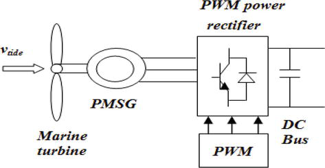
As shown in Figure 1, the MCT structure is composed of marine turbine, a permanent magnet synchronous machine coupled to a DC bus through a PWM power rectifier.
Figure 1.
Marine current turbine structure.
2.1 Resource model
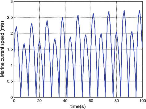
Tidal currents are proven by the effect of the moon and to a lesser degree, the sun, on the earth’s surface. Since the moon is so much closer to the earth than the sun, its pull has more influence on the tides, the magnitude of the tide-generating force is about 68% of moon and 32% of sun. Indeed, the moon’s gravitational pull forces the ocean to bulge outwards on opposite sides of the earth, which causes a rise in the water level in places that are aligned with the moon and a decrease in water levels halfway between those two places. This rise in water level is accompanied by a horizontal movement of water called the tidal current. Figure 2 shows the simulation curve of marine current speed.
Figure 2.
Marine current speed.
2.2 Marine turbine rotor model
The conversion of kinetic energy into mechanical energy is achieved by using a marine turbine rotor. The mechanic power for a marine current turbine has the same dependence as that of a wind turbine and is given by the following equation [8, 9]:
Pm=12Cpλβρπr2vt3E1
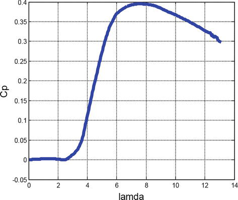
where ρ is the fluid density, r is the turbine radius, vt is the tidal speed, and Cp is the power coefficient; it presents the percentage of mechanical power, which can be extracted from the fluid stream by the turbine.
For typical MCTs, the maximum value of Cp for normal operation is estimated to be in the range of [0.35–0.5] [10]. Indeed, based on the experimental results and for a given turbine, the Cp can be approximated as an expression of the blade pitch angle β and the tip speed ratio λ and Ref. [11]. Figure 3 illustrates the Cp curve for simulations.
Figure 3.
Power coefficient curve Cp.
2.3 Generator model
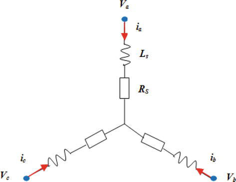
To model the PMSG, we will use two reference frame: the (abc) reference frame and the (dq) reference frame. The first one is the most used in the literature in the case of faulty conditions. The second is the (dq) reference frame without neglecting the zero-sequence component. Indeed, in the presence of short-circuit; this zero-sequence component is not zero.
The modeling of the PMSG will be developed in the next section in both cases: healthy and faulty conditions.
2.4 PWM power rectifier model
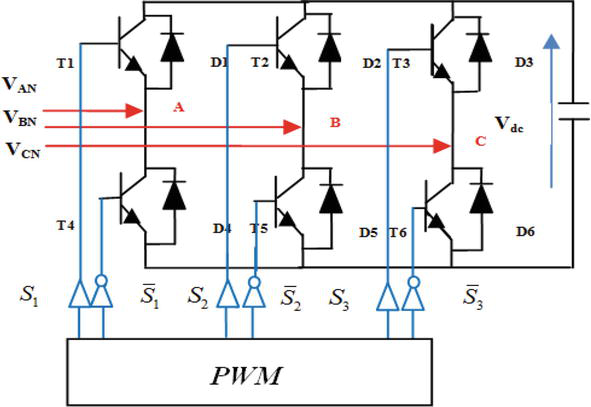
The PWM power rectifier uses the three-phase voltage sources provided by the PMSG.
As shown in Figure 4, this converter is composed of three legs, each leg features two semiconductor switches (Tk, Tk + 3 k = 1, 2, 3) with antiparallel connected freewheeling diodes (Dk, Dk + 3). The switches of the same leg are controlled by a PWM bloc in the form of a logic control signal Sk (k = 1, 2, 3) also known as gate signals, it is defined by:
where p is the pair pole number, Ω is the turbine speed, Tm is the mechanical torque, Tem is the electromagnetic torque, f is the viscosity coefficient, and J is the turbine and the PMSG inertia.
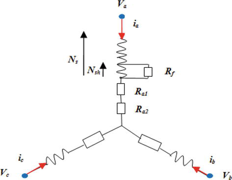
In this section and as shown in Figure 6, an inter-turn short-circuit is occurred in phase “a.”
Figure 6.
Three-phase stators winding with turn fault in phase “a.”
We define:
μ=NshNsE18
where.
Nsh: the number of shorted phase turns.
Ns: the total number of phase turns.
If μ = 0, the faulty model will reduce to a healthy model.
Rf is the fictitious resistance across the shorted winding to limit the short-circuit current [7], it defined by:
Rf=∞in healthy conditions0in faulty conditionsE19
The stator equations model is modified as follows:
vs=va1va2vbvcTE20
is=iaia−ifibicTE21
where va1 is the voltage across the non-shorted winding part, va2 is the voltage across the shorted winding part, and if is the additional current spawns by the short-circuit.
The resistance matrix is expressed as follows:
Rs=Ra1000Ra2000Rs000Rs000E22
where
Ra1=1−μRsRa2=μRsE23
The addition of rows 1 and 2 of Eq. (20) allows us to obtain new machine equations as follows [15]:
vsf=Rsis+dψsdt−Ra2if−dψfdtE24
where ψf is the short-circuit fault flux defined by:
ψf=LfifE25
Lf=La2+Ma1a2Ma2bMa2cTE26
We note that Eq. (24) is composed of two parts: a healthy part and a faulty part, caused by the short-circuit fault.
To solve this equation, we must add the expression of the voltage across the shorted winding part defined as follows:
In this section, simulation software has been set up by using the Matlab/Simulink environment. An inter-turn short fault is applied to phase “a” at t = 0.3 s.
The parameters used in simulation tests are displayed in Table 1.
MCT parameters
Turbine blade radius
0.87 m
Number of blades
3
Fluid density
1027.68 Kg/m3
Generator stator resistance
0.173 mΩ
Generator d-axis reference
0.085 mH
Generator q-axis reference
0.951 mH
Permanent magnet flux
0.112 Wb
Generator inertia
0.0048 kg.m2
Viscosity coefficient
8.5 10−3 Nm/s
Table 1.
MCT parameters.
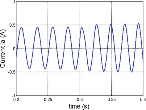
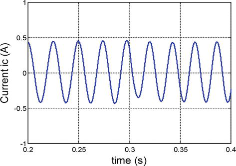
The waveforms given in Figures 7–9 show the three-phase currents, when (Rf = 1 Ω and μ = 0.1).
Figure 7.
Current ia before and after fault.
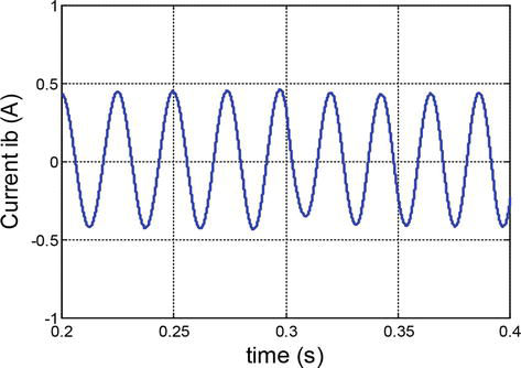
Figure 8.
Current ib before and after fault.
Figure 9.
Current ic before and after fault.
We note that the current magnitude in phase “a” increases after the application of the fault. Whereas, in phase “b” and phase “c,” the rise of current is very slight.
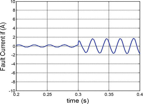
Figure 10 shows the current flowing through the fictitious resistance branch; we note that this current drops from zero to a sinusoidal form.
Figure 10.
Fault current if.
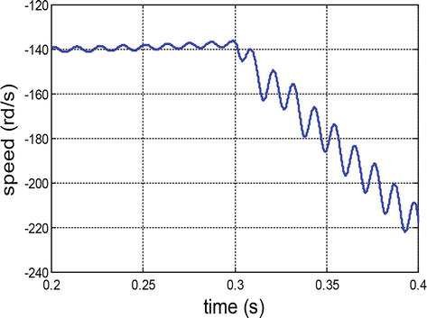
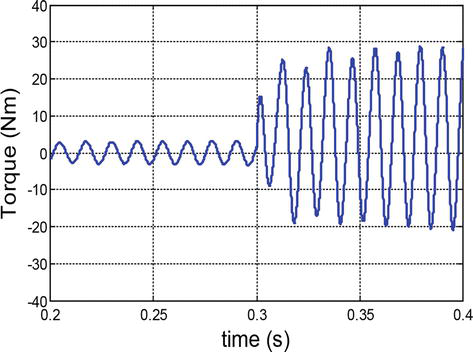
The speed and the torque are given in Figures 11 and 12. After the fault instant; we note that there is an appearance of important corrugations.
Figure 11.
Speed curve before and after fault.
Figure 12.
Torque curve before and after fault.
To study the impact of default between turns on the behavior of the machine, firstly, the simulation is done for different values of the default resistance, then, for the different number of shorted turns.
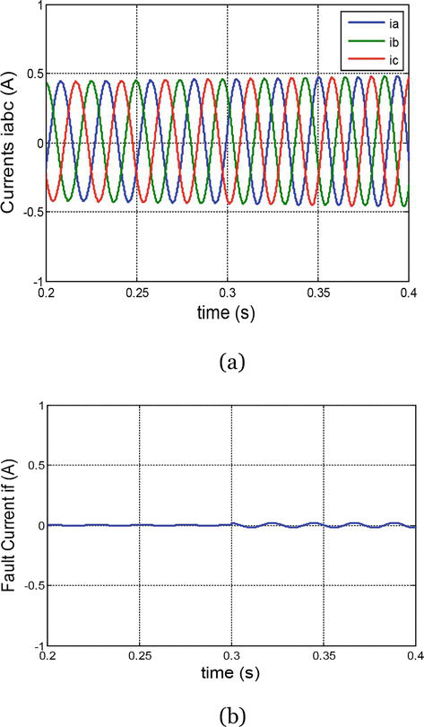
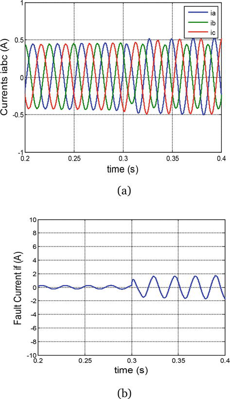
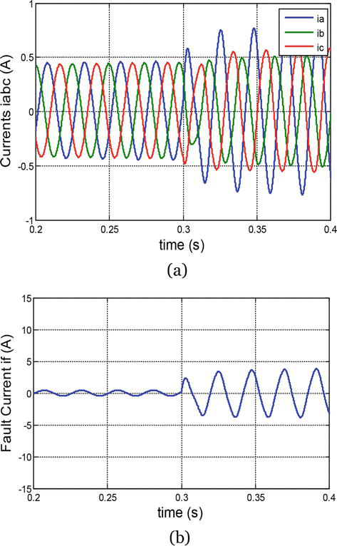
The three-phase currents and the current in the fictitious resistance are given in Figures 13–15. When the fault resistance decreases, the magnitude of the default phase current becomes more elevated than the other healthy phase currents. Also, the current in the fictitious resistance increases.
Figure 13.
(a) Phase currents iabc, (b) fault current if (Rf = 10 Ω).
Figure 14.
(a) Phase currents iabc, (b) Fault current if (Rf = 1 Ω).
Figure 15.
(a) Phase currents iabc, (b) Fault current if (Rf = 0.01 Ω).
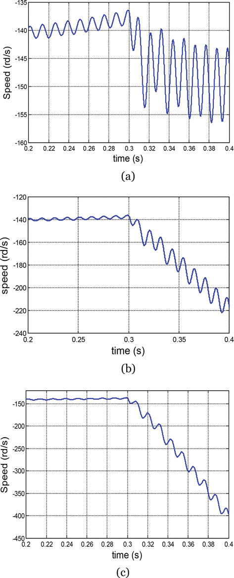
Figure 16 shows the evolution of the speed for a different number of shorted turns. We note that because of the increased number of shorted turns, the corrugations become increasingly important and the machine starts to unhook.
This chapter presents the modeling and simulation of a permanent magnet synchronous generator with inter-turn short circuits on the stator. The equations of the machine in healthy and faulty conditions are presented in both (abc) reference frame and (dq) reference frame. The main focus has been the study of the impact of this fault on the three-phase currents, speed, and torque. In addition, the impact of this fault is related to the default resistance and the number of shorted turns. The proposed system has been performed by using Matlab/Simulink.
References
1.Toumi S, Amirat Y, Elbouchikhi E, Trabelsi M, Mimouni MF, Benbouzid MEH. Second-order sliding mode for marine current turbine fault-tolerant control. In: the IEEE International Conference on Control Engineering & Information technology (CEIT’04); 16-18 December 2016; Hammamet. Tunisia: IEEE; 2016. pp. 1-6
2.Toumi S, Amirat Y, Trabelsi M, Elbouchikhi E, Mimouni MF, Benbouzid MEH. Backstepping control of a PMSG-based marine current turbine system under faulty conditions. In: Proceedings of the IEEE International Renewable Energy Congres (IREC’09); 20–22 March 2018, Hammamet. Tunisia: IEEE; 2018. pp. 1-6
3.Toumi S, Benelghali S, Trabelsi M, Elbouchikhi E, Amirat Y, Benbouzid MEH, et al. Modeling and simulation of a PMSG-based marine current turbine system under faulty rectifier conditions. Electric Power Components and Systems. 2017;45:715-725
4.Conroy JF, Watson R. Frequency response capability of full converter wind turbine generators in comparison to conventional generation. IEEE Transactions Power Systems. 2008;23:649-656
5.Zhou Z, Scuiller F, Charpentier JF, Benbouzid MEH, Tang T. Grid-connected marine current generation system power smoothing control using supercapacitors. In: Proceedings of the IEEE Annual Conference on IEEE Industrial Electronics Society (IECON’38); 25–28 October 2012, Montreal. Canada: IEEE; 2012. pp. 1-6
6.Bachir S, Tnani S, Trigeassou JC, Champenois G. Diagnosis by parameter estimation of stator and rotor faults occurring in induction machines. IEEE Transactions Industrial Electronics. 2006;53:963-973
7.Farouq JA, Raminosoa T, Djerdir A, Miraoui A. Modelling and Simulation of stator winding inter-turn faults in permanent magnet synchronous motors. COMPEL Journal. 2008;27:887-896
8.Toumi S, Amirat Y, Elbouchikhi E, Trabelsi M, Benbouzid MEH, Mimouni MF. A comparison of fault-tolerant control strategies for a PMSG-based marine current turbine system under converter faulty conditions. Journal of Electrical Systems. 2017;13:472-488
9.Benelghali S, Balme R, Le Saux K, Benbouzid MEH, Charpentier JF, Hauville F. A simulation model for the evaluation of the electrical power potential harnessed by a marine current turbine. IEEE Journal on Oceanic Engineering. 2007;32:786-797
10.Toumi S, Benelghali S, Trabelsi M, Elbouchikhi E, Benbouzid MEH, Mimouni MF. Robustness analysis and evaluation of a PMSG-based marine current turbine system under faulty conditions. In: Proceedings of the IEEE International Conference on Sciences and Techniques of Automatic Control and and Computer Engineering (STA’15); 21–23 December 2014; Hammamet. Tunisia: IEEE; 2014. pp. 631-636
11.Toumi S, Amirat Y, Elbouchikhi E, Trabelsi M, Benbouzid MEH, Mimouni MF. A simplified mathematical approach for magnet defects modeling in PMSG-based marine current turbine. In: Proceedings of the IEEE International Conference on Sciences and Techniques of Automatic Control and Computer Engineering (STA’17); 19–21 December 2016; Sousse. Tunisia: IEEE; 2016. pp. 552-557
12.Errami Y, Maaroufi M, Ouassaid M. Modelling and Control Strategy of PMSG Based Variable Speed Wind Energy Conversion System. In: Proceedings of the IEEE International Conference on Multimedia Computing and Systems (ICMCS); 7–9 April 2011; Quarzazate. Morocco: IEEE; 2011. pp. 1-6
13.Poddar G, Joseph A, Unnikrishnan AK. Sensorless variable-speed controller for existing fixed-speed wind power generator with unity-power-factor operation. IEEE Transactions Industrial Electronics. 2003;50:1007-1015
14.Weizheng Y, Woo K, Ruijie Z, Wei G, Yue W. Analyze of current control strategy based on vector control for permanent-magnet synchronous generator in wind power system. In: Proceedings of the IEEE International Power Electronics and Motion Control Conference (IPEMC’6); 17–20 May 2009; Wuhan. China: IEEE; 2009. pp. 2209-2212
15.Tallam RM, Habetler TG, Harley RG. Transient model for induction machines with stator winding turn faults. IEEE Transactions Industrial Applications. 2002;38:623-627
Written By
Sana Toumi, Mohamed Benbouzid and Mohamed Faouzi Mimouni
Submitted: 30 October 2022Reviewed: 13 November 2022Published: 21 December 2022
 Open access peer-reviewed chapter