Open Access is an initiative that aims to make scientific research freely available to all. To date our community has made over 100 million downloads. It’s based on principles of collaboration, unobstructed discovery, and, most importantly, scientific progression. As PhD students, we found it difficult to access the research we needed, so we decided to create a new Open Access publisher that levels the playing field for scientists across the world. How? By making research easy to access, and puts the academic needs of the researchers before the business interests of publishers.
We are a community of more than 103,000 authors and editors from 3,291 institutions spanning 160 countries, including Nobel Prize winners and some of the world’s most-cited researchers. Publishing on IntechOpen allows authors to earn citations and find new collaborators, meaning more people see your work not only from your own field of study, but from other related fields too.
To purchase hard copies of this book, please contact the representative in India:
CBS Publishers & Distributors Pvt. Ltd.
www.cbspd.com
|
customercare@cbspd.com
This chapter presents a simple method to efficiently predict the rotor speed for a sensorless vector control technique applied to induction motors (IMs). The motor is supplied by a Simplified Split-Source Inverter (S3I), which provides dc-boosting and ac-inversion processes during input voltage sag. It also has a wider modulation range and a lower harmonic content than conventional boosting inverters. With this contribution, it is possible to efficiently estimate the rotor position directly without needing a PI controller with fluctuated supply voltage. The proposed strategy can be divided into three parts. The first uses a dual-loop controller to obtain the reference DC-boosted voltage of the SSI and regulate the input current. The second is the suggested observer for speed detection, which is derived from the principles of phase axis relations of the adopted machine currents and the indirect rotor flux orientation control (IRFOC) approach. With a newly developed space vector modulation, the third part will generate the switching pulses of the inverter switches. A complete analysis has been conducted to ensure the observability of the proposed technique. A series of PLECS simulations were conducted to verify the concept. The obtained results validate the proposed strategy with the S3I topology.
*Address all correspondence to: sherif.dabour@gcu.ac.uk
1. Introduction
Due to their low cost, high power density, and ability to withstand harsh environments, induction motors are the most popular motors in the industry [1, 2]. If this motor is directly connected to the grid, it operates at speeds determined by the line frequency and the number of poles. Due to the nonlinear relationship between motor current and torque, speed control is much more complex than DC motors. During the past few years, there have been numerous applications for induction motors, including pumps, blowers, and industrial applications. Although this control strategy is easy to implement and utilizes inexpensive hardware, it has poor performance and slow response times. Nevertheless, modern variable speed drive applications, such as electric vehicles (EVs), require high performance and fast dynamic response control systems.
To improve the dynamic responses of the electric drive systems, vector control strategies, such as the Field-oriented Control (FOC) method, are proposed [3, 4, 5]. According to this control method, flux is controlled by the amount of current generated on the d-axis, while the current component on the q-axis controls torque. Based on this approach, the induction motor mimics the dynamic behavior of a DC motor. The advantages of FOC include a wider speed range, better dynamic response, precise speed and position control, and field weakening (movement beyond base speed). In this control method, it is possible to directly measure the position of the field or the motor speed using the hall effect sensor. However, this method increases the system cost and the need for maintenance.
Low-cost and highly reliable controlled IM drives without mechanical sensors at the motor shaft have been demonstrated in the literature. It’s called sensorless vector control algorithms. In these algorithms, to replace the sensor, the stator voltages and currents at the motor terminals are measured to determine the rotor speed or position [3, 4, 5]. The dynamic equations of induction motors can be used to estimate several quantities, such as magnetic flux and frequency. However, these quantities often require expensive or difficult-to-implement physical sensors. This class only requires current and voltage sensors. Accurate knowledge of machine parameters and open equations for estimates is necessary. On the other hand, closed-loop observatories rely on flexible techniques that require more computational power [6, 7, 8, 9, 10, 11, 12, 13, 14, 15, 16, 17, 18].
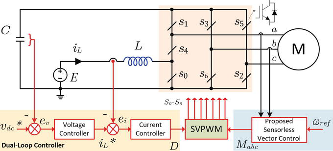
In general, a conventional voltage source inverter (VSI) can only achieve an output voltage that is limited by the input voltage level of the DC supply [19, 20]. Therefore, the new topology overcomes the performance-enhancing potential of DC-AC power converters, such as the Z-Source Topology Converter (ZSI). However, there are some issues, such as the lack of input current continuity and the use of four passive elements. Therefore, S3I (Simplified Split Source Inverter) topology can be used instead of ZSI, as shown in Figure 1, which handles the benefits of continuous input current and the reduced need for passive components [21]. Due to their advantages, the SSI is recently considered in different applications and control techniques, such as model predictive control [22], virtual synchronous control [23], dual motor drive [24], multilevel converter topologies [25] and multiphase machine drives [26].
This chapter aims to present a simple method for efficiently predicting the induction motor speed, which is supplied by S3I directly without a speed sensor. Basically, there are three parts to the control strategy. In the first part, the dc-link voltage vdc and the supply current iL, shown in Figure 1, are controlled by a dual-loop controller. In the second part, we propose a new speed observer derived from the principles of phase axis relationships of the adopted machine currents and indirect rotor flux orientation control (IRFOC). The third part will be used to generate the gating pulses of S3I with a modified SVPWM approach. Finally, the concept behind this chapter was verified using simulations.
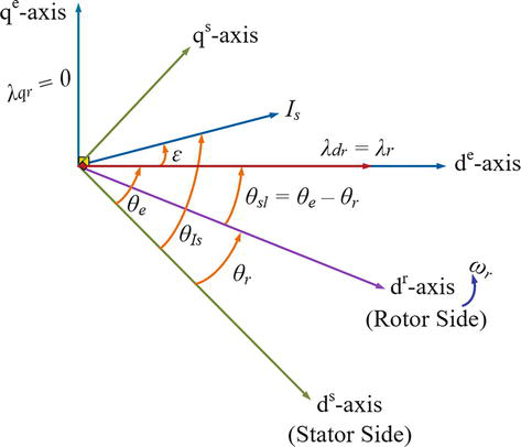
In general, vector control strategies are classified into direct field-oriented control (DFOC) and indirect field-oriented control (IRFOC) [3, 4, 5]. This chapter concerns the IRFOC technique. According to the field orientation principle of the three-phase IM, the magnetic flux and motor torque can be controlled independently by injecting appropriate stator currents or voltages [4]. The dynamic equations of the three-phase IM, which are presented by (1)–(6), can be simplified under certain conditions. For rotor-driven control, the rotor flux is aligned with the excitation frame (λdr=λr) and the expression is simplified so that λqr equals zero (λqr=0). Since the resulting motor’s torque and flux are decoupled. In this way, the IM can be controlled like a DC motor [2]. In this technique, the synchronous speed required to maintain the orthogonal orientation of vectors λr and ir in field-oriented control (FOC) is denoted by ωe∗. For the proposed orientation of the rotor winding field, the IM phase-axis relationship is shown in Figure 2.
Figure 2.
Phase-axis relationship of the IM for the proposed control strategy.
The required slip speed ωr and the desired current is∗ to produce the torque Te∗ and the desired magnetic flux λr∗ are calculated from the motor equations and the orientation conditions of the magnetic field. Manipulating the equilibrium equations, we obtain the following equation, which represents an indirect vector controller:
iqs∗=232PLrLmTe∗λrE7
ids∗=λr∗LmE8
Furthermore, the angular reference speed ωe∗ can be obtained from the machine rotor speed ωr, and the slip speed ωsl as follows
ωe∗=ωsl+ωrE9
Note that the relevant frame angle θe can be found directly by integrating ωe∗. In the indirect FOC (IRFOC) technique, the slip speed, ωsl is determined from [2], as follows
ωsl=LmrrλrLriqsE10
Based on the principles of the introduced IRFOC, the real flux of the rotor λr is calculated as:
Lrrrdλrdt+λr=LmidsE11
The stator current component corresponding to the dq-axis can be determined from the actual three-phase currents using the desired frame angle (frame angle, θf=θe) with a suitable conversion (given Ktr):
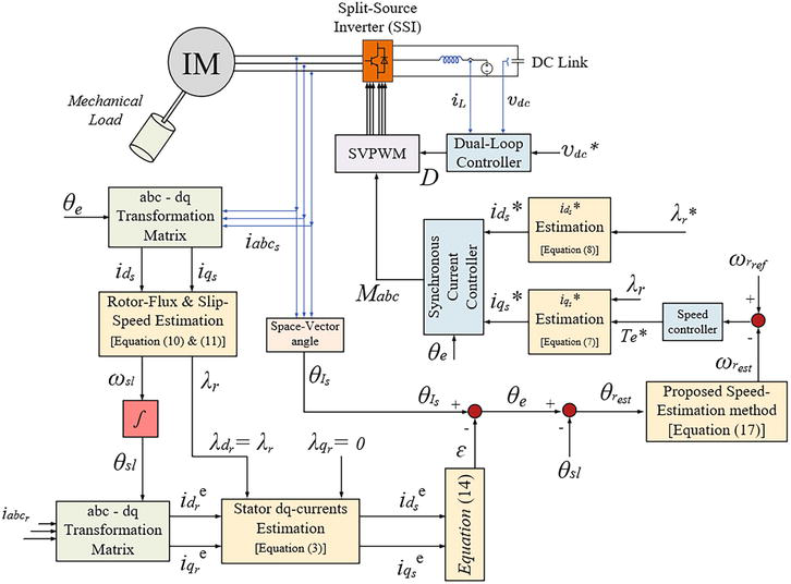
It is worth noting that the vector control algorithm for the desired orientation depends on the rotor speed signal. However, the necessary speed sensor increases the overall system cost and requires more maintenance. Therefore, it is recommended to implement speed control based magnetic field orientation using a more efficient sensorless rotor speed monitor. Therefore, this section explores a simple method to detect the speed of the IM without an additional observer. The block diagram of the proposed sensorless control strategy is shown in Figure 3. The main control procedure applied can be illustrated as follows:
Figure 3.
The main structure of the proposed sensorless vector-control system.
First, the phase angle, θIs and the current space vector of the stator side, is are determined from the actual three-phase signals as follows
is=k·iabcsθIs=angleisE13
where k=2/32/3ej2π32/3ej4π3
In addition, the slip angle θsl can be obtained directly from the relevant slip angle velocity integration process using (10). Therefore, the corresponding amount of the expected rotor current on the dq axis is given using a transformation matrix, where Ktr is the angle of the indicated magnetic flux direction (θf=θsl).
Then, the corresponding shaft stator current dq can be determined using the IRFOC (λqr=0) in (3) and (11). Therefore, the relevant phase angle is expressed as
ϵ=tan−1iqseidseE14
Hence, the desired frame angle, θeθe can be finally predicted as:
θe=θIs−εE15
Finally, the intended estimated value of the machine rotor position can be given, with the aid of (9), as:
θrest=θe−θslE16
After sensing the IM position signal, the corresponding speed signal can be obtained directly using the procedure for deriving the rotor position (16). However, derivative problems can create a lot of noise in the resulting speed signal. This noise affects the overall efficiency of sensorless vector control techniques. Refs. [27, 28, 29] have used extra observers to solve this problem. However, these observatories are complicated and expensive. Then, as shown in eq. (17), a simple method is proposed [30] to perform velocity estimation without being affected by noise.
ωrest=dθrestdt=ddttan−1YX=dYdtX−dXdtYE17
Here, the variables “X” and “Y” are trigonometric functions of the rotor pitch angle θrest.
By adjusting the rotor flux, λr∗ and the electromagnetic torque, Te∗ we can obtain the command values of the stator current ids∗ and iqs∗ can be obtained in the expected frame dq as shown in Figure 3. Therefore, the corresponding three-phase stator current can be specified using the transformation matrix Ktr along with the desired frame angle θe.
The three-phase modulating signals, Mabc are determined using Synchronous Current Control (SSC) technique, as shown in Figure 3. In SCC, two pairs of current controllers are used to evaluate reference voltages in the synchronous reference frame. After these voltages have been converted to three-phase, they are utilized as references for modulation.
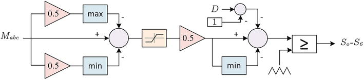
Finally, the SVPWM modulator handles the signals from the dual-loop controller and the sensorless controller to obtain the gating pulses of the inverter, as shown in Figure 4 [31].
Figure 4.
Block diagram for generating the gating pulses using the proposed SVPWM approach for the S3I.
It is worth noting the dc boosting factor, B of the analyzed inverter circuit (Bis defined as the ratio between the capacitor average voltage and the supply voltage) and can be calculated from the charging duty cycle, D, which is determined from the dual-loop controller for the dc-side and is governed by [31].
B=11−DE18
Moreover, the voltage gain, which is defined as the ratio between the peak value of the phase voltage to the supply voltage, is [31].
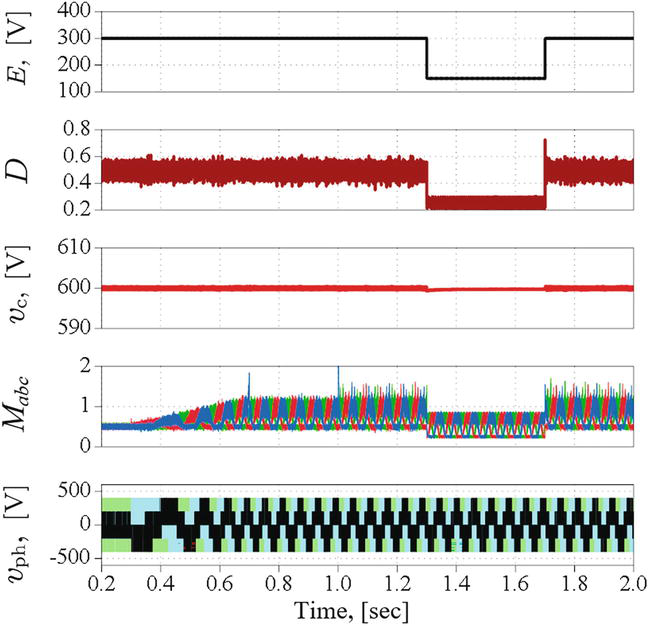
Simulation results for the supply voltage, charging duty cycle, capacitor voltage, modulating signals and motor phase voltages, respectively, of the suggested sensorless control strategy of the proposed system for voltage dip from 300 V to 150 V.
Figure 6.
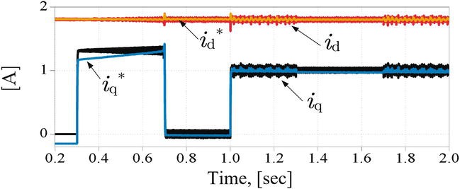
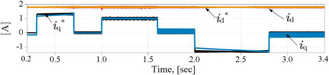
Simulation results for the reference and actual motor current dq-axes components of the suggested sensorless control strategy of the proposed system for voltage dip from 300 V to 150 V.
Figure 7.
Simulation results for the reference and actual motor current dq-axes components of the suggested sensorless control strategy of the proposed system for voltage dip from 300 V to 150 V.
Figure 8.
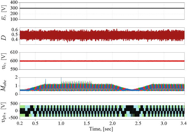
Simulation results for the supply voltage, charging duty cycle, capacitor voltage, modulating signals and motor phase voltages, respectively, of the suggested sensorless control strategy of the proposed system for a constant supply voltage of 300 V.
Figure 9.
Simulation results for the reference and actual motor current dq-axes components of the suggested sensorless control strategy of the proposed system for a constant supply voltage of 300 V.
Figure 10.
Simulation results for the reference and actual motor current dq-axes components of the suggested sensorless control strategy of the proposed system for a constant supply voltage case under different loading and speed conditions.
Parameter
Value
Parameter
Value
Torque limit
3.75
DC voltage controller
kp
0.5
Initial rotor flux
1.525
ki
0.04
Speed controller
kp
2.67
DC current controller
kp
1
ki
118.5
ki
0.5
Table 2.
Parameters and gains for Sensorless and dual-loop controller.
4.1 Supply voltage dip
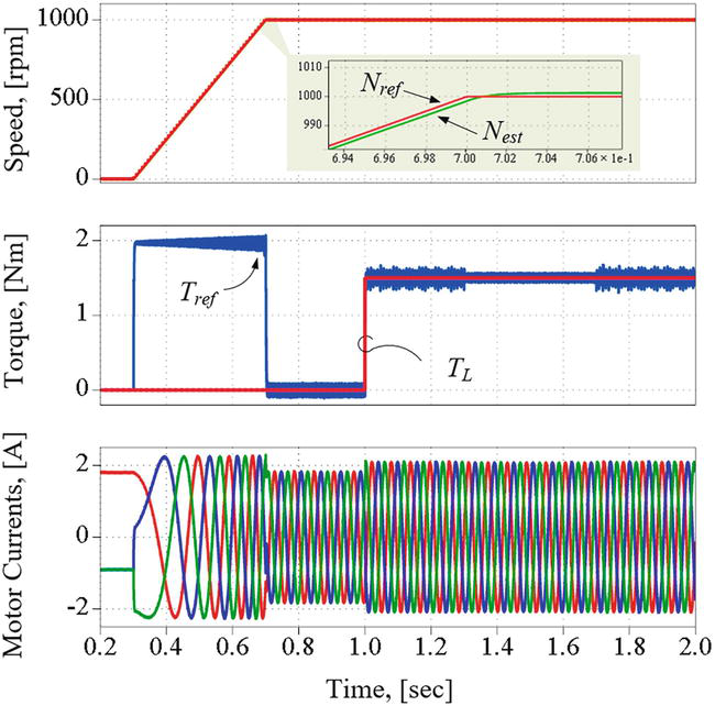
In this case, it is assumed that the supply voltage is 300 V for the first 1.3 sec of the simulation. Afterwards, it was reduced to 150 for 0.4 sec and then restored to its original value. Moreover, the motor is accelerated at t = 0.3 sec from the standstill to 1000 rpm at no-load in 0.7 seconds. After that, a load of 1.5 Nm is applied at t = 1 sec.
The waveforms of supply voltage, charging duty cycle, dc-link voltage and motor terminal voltage are shown in Figure 5. Moreover, Figures 6 and 7 show the actual and reference dq components of the motor current; the motor reference and estimated speed; the reference and actual motor torque; and actual phase currents waveforms, respectively, for the case study. It can be observed from these results that:
The proposed topology initially boosts the supply voltage from 300 to 600 volts at the dc-link capacitor.
Furthermore, the dual loop controller can follow the reference dc-link voltage and the inductor current references despite disturbances with small ripples.
The duty cycle, D is changed during the voltage dip period to obtain a constant dc-link capacitor voltage at the capacitor terminal (600 V) and, therefore, the required voltage at the motor terminals.
The motor currents’ actual flux and torque components are fully decoupled and follow the reference components generated from the IFOC very well.
The motor runs from the standstill to 1000 rpm in about 0.4 sec, and the motor torque follows the reference torque with a fast response.
An accurate motor speed estimation is achieved from the simulation results of the proposed algorithm.
In addition, the motor currents have sinusoidal waveforms with a THD of less than 3.4%.
4.2 Constant supply voltage
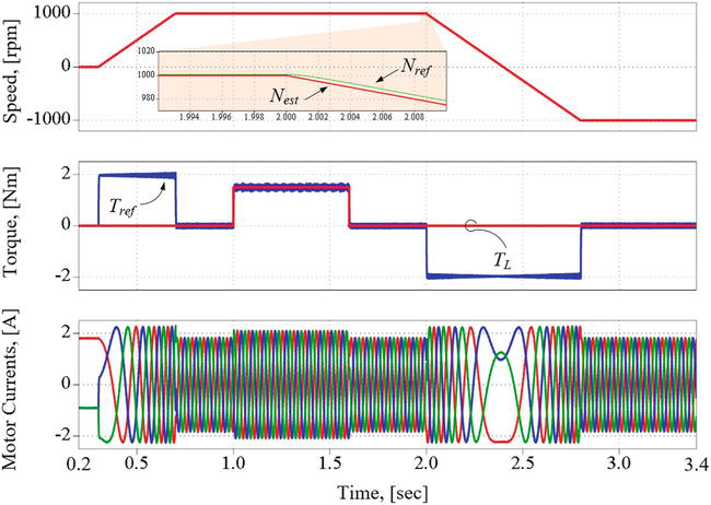
In this case, the supply voltage is assumed to be a constant of 300 V. An acceleration with ramp change from 0 to 1000 rpm at no-load during the interval from t = 0.3 to t = 1 second, then a load of 1.5 Nm is applied from t = 1 to t = 1.6 sec. After that, speed reversal during the interval from t = 2 to t = 2.8 sec is applied to 1000 rpm in the backward direction of the motor. A sample of the obtained results is shown in Figures 8–10.
It can be observed from the results that:
The dc-link voltage is boosted and regulated at its reference value, as in case 1.
The actual torque follows the reference torque very well. In addition, the flux and torque current components are fully decoupled.
It can also be noted that the motor currents increase due to the loading effect at 1 sec but still have sinusoidal waveforms.
The speed reversal transient is also examined between t = 2 and t = 2.8 sec.
The responses show that the actual motor speed and the estimated speed from the proposed sensorless observer closely follow the reference value, resulting in rapid speed reversal, with torque in the limit.
The change of phase sequence in the stator current is observed because of the change in the rotational direction.
The above analysis and simulation results show that the proposed speed observer has been validated for indirect field-oriented control techniques with a three-phase induction motor drive based on a simplified split-source inverter.
In this study, a simple topology has been investigated and implemented to efficiently predict the rotor speed signal for a proposed sensorless vector control technique for an induction motor (IM) using a simplified split-source inverter configuration. The proposed observer for detecting the rotor speed has been obtained based on the principle of the phase-axis relationship of the applied machine current and indirect magnetic flux orientation control (IRFOC) method. It has been confirmed that the proposed observer procedure was simple and did not require an additional observer to detect IM rotor speed. The analysis supported by the results has confirmed the efficient performance and observability of the presented topology to predict IM speed signal with the implementation using split-source inverters compared to conventional inverters. In addition, the results have assured the controllability and robustness of the proposed observer for the sensorless control system that uses the vector control technique to drive the induction motor.
1.Wu B, Lang Y, Zargari N, Kouro S. Power Conversion and Control of Wind Energy Systems. Hoboken, New Jersey: Wiley-IEEE Press; 2011
2.Campanari S, Manzolini G, Iglesia FGDL. Energy analysis of electric vehicles using batteries or fuel cells through well-to-wheel driving cycle simulations. Journal of Power Sources. 2009;186:464-477
3.Zeb K et al. Indirect vector control of induction motor using adaptive sliding mode controller. In: 2016 Australian Control Conference (AuCC). Newcastle, NSW, Australia: IEEE; 2016. pp. 358-363. DOI: 10.1109/AUCC.2016.7868216
4.Gobinath D, Vairaperumal K, Elamcheren S. Simplified approach on feed forward vector control of induction motor with PI controller using SPWM technique. In: 2014 IEEE International Conference on Computational Intelligence and Computing Research. Coimbatore, India: IEEE; 2014. pp. 1-4. DOI: 10.1109/ICCIC.2014.7238307
5.Saha S, Nayak B. Sensorless vector control and selection of observer gain for speed control of indirect vector control induction motor drives. In: 2017 Second International Conference on Electrical, Computer and Communication Technologies (ICECCT). Coimbatore, India: IEEE; 2017. pp. 1-7. DOI: 10.1109/ICECCT.2017.8117987
6.Griva G, Ilas C, Eastham JF, Profumo F, Vranka P. High performance sensorless control of induction motor drives for industry applications. In: Proceedings of the Power Conversion Conference - PCC ’97. Vol. 2. Nagaoka, Japan: IEEE; 1997. pp. 535-539. DOI: 10.1109/PCCON.1997.638143
7.Xu W, Hussien MG, Liu Y, Allam SM. Sensorless control of ship shaft stand-alone BDFIGs based on reactive-power MRAS observer. Journal of Emerging and Selected Topics in Power Electronics. 2021;9(2):1518-1531
8.W. Xu, Mohamed G. Hussien, Y. Liu, I. Rabiul, S. Allam, “Sensorless voltage control schemes for brushless doubly-fed induction generators in stand-alone and grid-connected applications,” IEEE Transactions on Energy Conversion, vol. 35, no. 4, pp. 1781-1795, Dec. 2020
9.Rokhforoz P, Poshtan J. Rotor speed and resistance estimation using robust extended Kalman filter for sensorless vector control of induction motor drives. In: The 6th Power Electronics, Drive Systems & Technologies Conference (PEDSTC 2015). Tehran, Iran: IEEE; 2015. pp. 304-309. DOI: 10.1109/PEDSTC.2015.7093292
10.Nadh G, Syamkumar U, Jayanand B. Sliding mode observer for vector control of induction motor. In: 2016 International Conference on Next Generation Intelligent Systems (ICNGIS). Kottayam, India: IEEE; 2016. pp. 1-6. DOI: 10.1109/ICNGIS.2016.7854042
11.Hussien MG, Hassan AE. Mathematical analysis of the small signal model for voltage-source inverter in SPMSM drive systems. In: 2019 21st International Middle East Power Systems Conference (MEPCON). Cairo, Egypt: IEEE; 2019. pp. 540-549. DOI: 10.1109/MEPCON47431.2019.9008172
12.Kouchih D, Hachelaf R, Boumalha N, Tadjine M, Boucherit MS. Improvement of sensorless vector controlled induction motor drives using a new algorithm for the rotor resistance adaptation. In: 2016 5th International Conference on Systems and Control (ICSC). Marrakesh, Morocco: IEEE; 2016. pp. 67-71. DOI: 10.1109/ICoSC.2016.7507027
13.Gadoue SM, Giaouris D, Finch JW. Sensorless control of induction motor drives at very low and zero speeds using neural network flux observers. IEEE Transactions on Industrial Electronics. 2009;56(8):3029-3039
14.Xu W, Junejo A, Liu Y, Hussien MG, Zhu J. An efficient anti-disturbance sliding-mode speed control method for PMSM drive systems. IEEE Transactions on Power Electronics. 2021;36(6):6879-6891
15.Boldea I et al. Fractional kVA rating PWM converter doubly fed variable speed electric generator systems: An overview in 2020. IEEE Access. 2021;9:117957-117968. DOI: 10.1109/ACCESS.2021.3101907
16.Cirrincione M, Pucci M, Cirrincione G, Capolino GA. Sensorless control of induction motor drives by new linear neural techniques. In: 2006 12th International Power Electronics and Motion Control Conference. Portoroz, Slovenia: IEEE; 2006. pp. 1820-1829. DOI: 10.1109/EPEPEMC.2006.4778670
17.Liu Y, Xu W, Long T, Blaabjerg F. An improved rotor speed observer for standalone brushless doubly-fed induction generator under unbalanced and nonlinear loads. IEEE Transactions on Power Electronics. 2020;35(1):775-788
18.Hussien MG, Liu Y, Xu W. Robust position observer for sensorless direct voltage control of stand-alone ship shaft brushless doubly-fed induction generators. CES Transactions on Electrical Machines and Systems. 2019;3(4):363-376
19.Peng FZ. Z-source inverter. IEEE Transactions on Industry Applications. 2003;39(2):504-510
20.Caceres R, Barbi I. A boost dc–ac converter: Analysis, design, and experimentation. IEEE Transactions on Power Electronics. 1999;14(1):134-141
21.Abdelhakim A, Mattavelli P, Spiazzi G. Three-phase Split-source inverter (SSI): Analysis and modulation. IEEE Transactions on Power Electronics. 2016;31(11):7451-7461
22.Bakeer A, Dabour SM, Gowaid IA, Aboushady AA, Elgenedy MA, Farrag ME. Enhanced finite control set-model predictive control for three-phase split-source inverters. In: 2022 57th International Universities Power Engineering Conference (UPEC). Istanbul, Turkey; 2022. pp. 1-6. DOI: 10.1109/UPEC55022.2022.9917867
23.Abou-Hussein WM, Dabour S, Hamad MS, Rashad EM. Model predictive control based virtual synchronous generator for parallel-connected three-phase split-source converters in islanded AC microgrids. Energy Reports. 2023;9:1696-1706. DOI: 10.1016/j.egyr.2022.12.075
24.Dabour SM, Abdel-Khalik AS, Ahmed S, Massoud A. An optimal PWM technique for dual-output nine-switch boost inverters with minimum passive component count. IEEE Transactions on Power Electronics. 2021;36(1):1065-1079. DOI: 10.1109/TPEL.2020.3001372
25.AbdulSalam M, Dabour SM, Rashad EM. Cascaded multilevel split-source inverters: Analysis and modulation. In: 2019 21st International Middle East Power Systems Conference (MEPCON). Cairo, Egypt; 2019. pp. 1204-1209. DOI: 10.1109/MEPCON47431.2019.9008050
27.Mousa MG, Allam SM, Rashad EM. A sensorless scalar-control strategy for maximum power tracking of a grid-connected wind-driven brushless doubly-fed reluctance generator. In: The 4th International Conference on Electric Power and Energy Conversion Systems (EPECS’15). UAE: American University of Sharjah; 2015. pp. 1-6
28.Mousa MG, Allam SM, Rashad EM. Sensored and sensorless scalar-control strategy of a wind-driven BDFRG for maximum wind-power extraction. Journal of Control and Decision. 2018;5(2):1-19
29.Hussien MG, Xu W, Liu Y, Allam SM. Rotor speed observer with extended current estimator for sensorless control of induction motor drive systems. Energies. 2019;12:3613
30.Hussien MG, Dabour SM, Alotibi M, Omara AM, Mansour DEA. An Improved Sensorless Control of Induction Motor Drive-Based Split-Source Inverters. In: 2021 22nd International Middle East Power Systems Conference (MEPCON). Assiut, Egypt; 2021. pp. 378-382. DOI: 10.1109/MEPCON50283.2021.9686250
31.Dabour SM et al. Modeling and control of single-stage quadratic-boost Split source inverters. IEEE Access. 2022;10:24162-24180. DOI: 10.1109/ACCESS.2022.3153510
Written By
Sherif Dabour, Mohamed Hussien, Ahmed A. Aboushady and Mohamed Emad Farrag
Submitted: 09 January 2023Reviewed: 02 February 2023Published: 27 April 2023
 Open access peer-reviewed chapter