Open Access is an initiative that aims to make scientific research freely available to all. To date our community has made over 100 million downloads. It’s based on principles of collaboration, unobstructed discovery, and, most importantly, scientific progression. As PhD students, we found it difficult to access the research we needed, so we decided to create a new Open Access publisher that levels the playing field for scientists across the world. How? By making research easy to access, and puts the academic needs of the researchers before the business interests of publishers.
We are a community of more than 103,000 authors and editors from 3,291 institutions spanning 160 countries, including Nobel Prize winners and some of the world’s most-cited researchers. Publishing on IntechOpen allows authors to earn citations and find new collaborators, meaning more people see your work not only from your own field of study, but from other related fields too.
To purchase hard copies of this book, please contact the representative in India:
CBS Publishers & Distributors Pvt. Ltd.
www.cbspd.com
|
customercare@cbspd.com
The chapter is related to the safe and energy-efficient motion of autonomous drones and describes the developed novel immune neural network-based machine learning technology for its control. The technology is inspired by two biological systems – immune system and neural networks and their artificial analogs and evolutionary theory. The developed novel mathematical models and algorithms for this technology allow skipping the preliminary supervised training step and adapted for real-time continuous unsupervised self-learning of the drone to recognize the dangerous situation, to prevent the collision by making control decisions autonomously and continuously learning to keep optimal energy consumption during the motion. The chapter includes the study of existing neural network-based solutions for the recognition and prevention of dangerous situations and energy efficiency of drones, describes the developed target function and algorithm for immune neural network machine learning technology and simulation and experimental results proving the efficiency of this technology.
*Address all correspondence to: mihails.gorobecs@rtu.lv
1. Introduction
Drones have already been integrated into numerous activities, including inspecting hazardous objects, delivery services, people searching, fulfilling military objectives, agriculture, etc. Furthermore, photographers worldwide are increasingly embracing modern methods and technologies to enhance their photography during celebratory events. An interesting highlight is that in Australia, drones come equipped with sophisticated artificial intelligence-driven software, enabling them to distinguish boats and different marine life in real-time with an impressive 90% accuracy [1]. Amazon legally delivered its first Prime order in the United Kingdom in December 2016 [2]. And the use of drones still continues to spread to various areas.
Although most drones are currently controlled by human operators using remote controls to dictate their speed and trajectory, this approach may not be the most productive use of human time and effort in an era focused on automation and optimization. Additionally, relying on human operators leaves room for potential mistakes, which could lead to undesirable consequences. That is why the use of intelligence systems in drones is developing also.
For instance, the Patroller multi-sensor long endurance quadcopter was specifically designed to cater to the requirements of armed forces, intelligence operations, operational support, and maritime surveillance. What sets it apart is its autonomous launch system, enabling it to take off from airports without any need for adjustments to ground facilities. With an impressive endurance of 20 hours and a payload capacity of up to 250 kg, the Patroller is well-suited for prolonged missions [3].
There are bunches of areas where drones are used: military purposes; patrolling and searching tasks; order delivery; mapping of landslides, hurricanes or other cataclysms affected area; infested crop damage assessment; 3-dimensioinal terrain model construction, etc.
Such tasks as patrolling or searching require a team of drones working in the same area. When dealing with tasks that involve multiple drones, there is an added risk of potential collisions between them. For example, if multiple drones are assigned to search for the same object, and each drone is programmed to reach its own specific destination, there is a possibility that all drones may converge on nearly the same coordinates, increasing the risk of a collision. Another problem with the use of autonomous drones is untimely battery discharge, which can lead to the loss of the drones. That is why the problem of the safe and energy-efficient drive of autonomous drones is important and needs to be well studied.
Analysis of the research base reveals that currently, the majority of energy-saving solutions are related to route calculation and trajectory planning for unmanned vehicles, as well as energy-saving algorithms for other equipment unrelated to electric drive systems. Only a few studies focused on reducing energy consumption explore the mechanical and electrical properties of power devices, but not connected with autonomous drones and machine learning.
The scientific novelty of this research is the technology for the drone embedded system, which is able to learn in real-time to avoid crashes and control the motion with optimal energy consumption without any preliminary datasets, pretraining, and a teacher.
Authors named it as immune neural network (INN). It is a symbiosis that uses the best features of artificial neural networks (ANN) and artificial immune system (AIS). Separately each of them has a bunch of disadvantages. ANN requires preliminary training, may be overtrained, etc. AIS does not require training, but the optimization requires time and may not be used for real-time control. Novel INN system combines the possibilities of ANN and AIS is adapted for real-time safety and energy control.
The main hypothesis is that an immune neural network can make control decisions to prevent drone collisions with better performance than a traditional neural network in this task and is able to reduce the energy consumption of autonomous unmanned vehicles – drones.
The first part of the chapter contains an analysis of the existing types of solutions of the problem. The second part is devoted to the developing the novel system structure, which could help to make the proposed system cheaper, faster, and easier to implement. The target function of the proposed novel INN is described in the third part of the chapter. The fourth part is devoted to the proposed algorithm, based on the novel INN machine learning technology. The last part of the chapter is devoted to the results of testing the efficiency of the developed algorithm. The developed algorithm was tested with the help of computer modeling.
2. Review of the scientific research and literature about autonomous electric transport control
A research paper [4] previously proposed a method for real-time traffic flow parameter estimation from unmanned aerial vehicle (UAV) video, which relied on an ensemble classifier and optical flow. In contrast, the system presented in this study eliminates the need for additional infrastructure embedded objects, or/and devices. Two other articles [5, 6] also delve into motion control tasks for UAVs, both referencing the Lyapunov method. Comparing the motion control of aerial vehicles with surface transport allows concluding that of surface autonomous vehicles have a higher probability of collision because there is no ability to change the altitude component. A hierarchical collision-avoidance strategy is proposed as a theoretically approach for high-speed self-driving vehicle collision-avoiding task solving [7]. Fuzzy logic and FMCW radar (Frequency-Modulated Continuous Wave) usability for motion control task solving are described in research [8], but this system also is not provided with surrounding environment visual monitoring elements or sensors. The author presented a doctoral thesis in ref. [9], that is devoted to knowledge extraction from trained ANN. Research described in this research proposes a novel ANN, that does not require previous training, the proposed system is unsupervised and does not need a teacher.
In the research discussed in ref. [10], novel drone-following models are introduced for effective drone management within the transportation management system. These models operate on the fundamental premise that drones navigate by following a leading drone. But in difference with this research, in ref. [10] several important situations were not considered, like safe distance is measured not only in the drone directly in front but also in two drones beside, or increasing the number of drones. Intelligent electric vehicle motion and crossroad control using genetic algorithms is proposed in paper [11].
The book published, that was devoted to the scientific results: “Unmanned Electrical Vehicles and Autonomous System Simulation”. This book and its offshoots were prepared to provide a comprehensive introduction to the domain of the autonomous system [12]. The book was also mentioned artificial intelligence for autonomous drives, but no specific solutions, like ANN, were mentioned there.
The conventional ANN requires adjustments or fine-tuning to adapt to individual situations or tasks. In simpler terms, the traditional ANN uses the current weights as a starting point for the next round of re-training. However, this process can be time-consuming due to the wide variety of situations it needs to handle [13]. The INN proposed in this study includes an immune memory (IM) that retains information from past successfully prevented collision scenarios. By referencing this memory to find similar situations and utilizing the stored weights as a foundation for re-training, the INN can considerably minimize the time needed for self-tuning when dealing with a similar problem. In ref. [14] a similar solution is proposed. The main idea of that research is a retraining of a static neural network, by using IM-based algorithm. In the solution presented in ref. [14], the approach involves creating the initial population (a set of chromosomes) by random means. This means that the population consists of fuzzy weights for ANN, and these weights are assigned random values during the generation process. In difference with that research, the main idea of this research is that input data are stored in the IM together with weights, that was used previously for solving this situation, that helps to reduce calculation time, which is very important for real-time systems, thus to reduce energy consumption. Also, the proposed novel algorithm allows retraining the neural network. In this research, no initial population is needed. Training can start even with an empty IM. The found solutions will be those that will be written in the IM and further adjusted.
3.1 General safety system structure for drone dangerous situation recognition and prevention task
System models can be divided into centralized, decentralized, and distributed.
In a centralized system, all computing power may be allocated to one user when no other users are attached to the system. Consequently, the execution time of all users’ applications will be increased if the mainframe serves many users [15].
In simpler terms, decentralization is a system model where decision-making occurs at different levels. In this approach, the larger system is subdivided into smaller segments or groups, allowing for a more manageable assessment of the system’s performance and the contributions of individuals within each group [16].
A distributed operating system is a unique type of operating system that spans across multiple objects. The goal is to offer a useful range of services, making all the machines appear and function as a unified single entity. These distributed operating systems collaborate on all the machines they manage, which can either operate independently or serve as resources within the broader distributed system [17].
Centralized, decentralized, and distributed system models were compared. The results of the comparison show that a distributed system is preferable because it is easier to implement and has less components, it is cheaper for infrastructure owners and it is not connected to the specific area. It has also a decreased time for reaction and decreased risk of system failure. That is why a distributed system was chosen for this research.
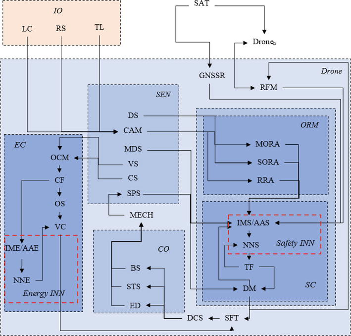
Figure 1 illustrates the schematic representation of the distributed system’s structure. Where: SAT – satellite, is a component that serves to acquire the real-time coordinates of an object’s position; Drone – autonomous drone; Dronen – other autonomous drones; MECH – mechanical part that is responsible for the drones moving; IO – infrastructure objects; CO – control system; SEN – sensor; EC – proposed novel immune neural network energy efficiency control module; SC – proposed novel immune neural network safety module; ORM – object recognition module, is using incoming video data for CNN to recognize other drones and drones that do not have the proposed embedded device as well as other objects in the visibility range; LC – different type of level crossings, if necessary; RS – signs, that limit the possible movement parameters on the concrete road/way section, if necessary; TL – different types of the traffic lights, if necessary; GNSS – GNSS receiver, is utilized to receive and determine the precise coordinates of the drone’s current location; RFM – serves the purpose of communication with other devices embedded in different drones and infrastructure objects; DS – distance sensor; CAM – camera is used to capture images of the surrounding environment; MDS – movement direction sensor, to receive the data of the drone movement direction; VS – voltage sensor; CS – current sensor; SPS – speed sensor to receive the data of the drone speed and acceleration; MORA – moving object recognition algorithm, to recognize moving objects such as human being, animals, other drones in the visibility range, based on the convolutional neural network (CNN); SORA – static object recognition algorithm, to recognize static objects such as fallen tree or broken car on the way of motion, based on the CNN; RRA – road recognition algorithm, to recognize the presence of turns and road profile, based on the CNN; IMS – immune memory for safety control; AAS – affinity algorithm for safety control; NNS – neural network as a part of the safety INN; DM – decision making module is responsible for making decisions to minimize risks and control the drone’s movement. It calculates appropriate curves and actions to achieve the desired speed and reach the target point on the designated route; TF – target function; CF – constraint formation to control signals; OS –optimal search algorithm module; VC – validation of the control signals; IME – immune memory for energy control; AAE – affinity algorithm for energy control; NNE – neural network as a part of Energy INN; SFT – safety check to avoid conflicts between safety control and energy control, where safety is a priority; DCS – drone control system, to control actions of the driver. If the driver receives the indications on the information display but does not react in time, then the driver control system sends the signal to the drone control system, and the proposed system intervenes in the drone control; BS – drone braking system, to control the stop of the drone, if applicable; ED – drone electric drive; STS – drone steering system to control the trajectory of motion, if applicable.
Figure 1.
Scheme of the general safety system structure for drone dangerous situation recognition and prevention task.
Microcontrollers embedded in each drone are responsible for executing various tasks. These tasks encompass object recognition, risk assessment, opportunity evaluation, and decision-making concerning adjustments to movement parameters and control signals.
The suggested system’s structure is based on the:
CNN-based subsystem for object recognition task;
ANN-based subsystem for drone collision probability evaluation and minimization task;
INN-based technology of machine learning for unsupervised safe drone control.
CNN and ANN are already known methods and are not described in this study.
3.2 Novel immune neural network-based technology of machine learning of autonomous drones for energy efficiency and collision prevention
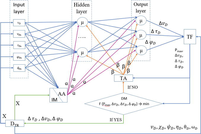
Novel INN-based technology (Figure 2) can be used in distributed systems. It obtains data, makes calculations and provides necessary solutions how to avoid collision in the context of one particular drone. It does not provide solutions for other participants.
Figure 2.
Immune neural network system structure of the drone.
3.2.1 Input data (X)
Data:
vD – speed of the own drone;
vDn – speed of other drones;
τDn – horizontal movement direction of the other drone relative to one’s own direction;
φDn – vertical movement direction of the other drone relative to one’s own direction;
dDn – distance till the possible crossing point with the other drone.
Number of parameters in the input data (X) depends on the situation – the number of other drones in the control area of own drone. There is one input parameter for own drone: speed. There are four input parameters for other drones: speed, horizontal movement direction in relation to the own drone, vertical movement direction in relation to the own drone, and distance till possible crossing point.
Data is received from the drone-embedded electronic device and is sent to the input layer of the immune neural network INN.
3.2.2 Input layer
The input layer of the INN receives input data (X).
Each drone takes into account only those drones, which are in its control area, in case to minimize the number of necessary calculations.
Input data (X) is ordered for a more accurate recognition of the situation. The goal is to order multiple drones in relation to the own drone to better understand their position and relative movement. Three parameters are used for ordering the drones: the horizontal movement direction τDn, the vertical movement direction φDn, and the distance to the crossing point dDn. Ordering of other drones is done according to the slope τDn to these objects, starting from 0°, clockwise. If multiple drones have the same value of τDn, then the ordering of these drones is done according to the slope φDn to these objects, starting from 0°, clockwise. If multiple drones have the same value of φDn, then the ordering of these drones is done according to the distance to the crossing point with these drone dDn. This method helps to describe the situation accurately.
Input data (X) are sent from the input layer to the affinity algorithm AA and hidden layer.
3.2.3 Affinity algorithm (AA)
The affinity algorithm AA examines all analogous situations stored in the immune memory IM and computes their errors (discrepancies) E. Situation with a smallest error (discrepancy) E is chosen and its identification number α is distributed to all μ neurons of the proposed INN. If there is no similar situation stored in IM immune memory, then situation number α = 0 is sent to the μ neurons.
3.2.4 Immune memory (IM)
Database, that contains input data about previous situations that were solved. Each situation has its’ number α.
To enhance the efficiency of the affinity algorithm (AA) and the storage of data in the immune memory (IM), a clustering technique is implemented. This approach avoids unnecessary searches for similar situations in scenarios with different numbers of participants. This ensures that, for instance, if four drones are involved in a potential collision scenario, there is no need to search for a similar situation among cases with only three participants. Clustering allows for faster and more efficient matching processes in the system.
3.2.5 Hidden layer
The hidden layer consists of specialized μ neurons.
Input data of each μ neuron of the hidden layer is:
input data (X);
situation number α received from the affinity algorithm AA;
signal β that indicates the need to recalculate the weights of μ neurons and is received from the training algorithm TA.
In the μ neuron number of situation α is stored together with a set of weights Wμ, that were used while solving the exact problem i.e. processing the similar input data. After number of the situation α is received, weights Wμ are chosen and training can be started. If there is no similar situation and α=0, then Wμ=0.
3.2.6 Output layer
Output layer consists of specialized μ neurons.
Input data of each μ neuron of the output layer is:
output data of the μ neurons of the hidden layer;
situation number α received from the affinity algorithm AA;
signal β that indicates the need to recalculate the weights of μ neurons and is received from the training algorithm TA.
In the μ neuron number of situation α is stored together with set of weights Wμ, that were used while solving the exact problem, similar as in the μ neuron of the hidden layer. After number of the situation α is received, weights Wμ are chosen and training can be started. If there is no similar situation and α = 0, then Wμ=0.
Output data of the output layer:
necessary horizontal movement direction change of the own drone ∆τD;
necessary vertical movement direction change of the own drone ∆φD;
necessary speed change of the own drone ∆vD.
3.2.7 Target function (TF)
Input data of target function TF:
necessary horizontal movement direction change of the own drone ∆τD;
necessary vertical movement direction change of the own drone ∆φD;
necessary speed change of the own drone ∆vD;
input data obtained directly from drone-embedded electronic device:
vD – actual speed of the drone;
χD – latitude of the drone’s actual position;
ψD – longitude of the drone’s actual position;
ηD – altitude of the drone’s actual position;
θD – actual horizontal movement direction of the drone;
ωD – actual vertical movement direction of the drone.
In the present study, the crossing points’ locations are variable, which adds complexity to the solution. The identified solution <∆vD,∆τD,∆φD> is affected by the distance to the crossing point. Thus, the evaluation of the target function TF requires the additional inputs <vD,χD,ψD,ηD,θD,ωD> obtained directly from the drone to re-calculate the crossing point, distance, and time to it.
Target function TF calculates the collision probability Pmax.
Output data of target function TF:
collision probability Pmax;
necessary horizontal movement direction change ∆τD;
necessary vertical movement direction change ∆φD;
necessary speed change ∆vD.
3.2.8 Decision module (DM)
Input data of decision module DM:
collision probability Pmax, received from the target function TF;
necessary horizontal movement direction change ∆τD, received from the target function TF;
necessary vertical movement direction change ∆φD, received from the target function TF;
necessary speed change ∆vD, received from the target function TF.
Decision module (DM) evaluates the found solution.
If collision probability Pmax is greater than acceptable (safe) collision probability Psafe and
If number of training iterations t is less than maximal possible number of iterations Tmax, that means the solution is not found yet and training must be repeated. Decision making module (DM) sends signal to the training algorithm (TA).
If number of training iterations t is bigger or equal than maximal possible number of iterations Tmax, that means that the situation can not be solved in the defined time, so speed reduction is done. Decision-making module (DM) sends signal to the drone-embedded electronic device to stop the drone vD=0.
If collision probability Pmax is less or equal than acceptable (safe) collision probability Psafe, then found solution <∆vD,∆τD,∆φD> is sent to the drone-embedded electronic device and match error εa between the current situation and situation chosen from the immune memory IM in the beginning of training is calculated:
if match error εa is bigger than maximal possible match error εlim, responsible for creation new record in the immune memory IM or replacing the existing, then IM saves the situation as a new record. Each μ neuron of the hidden and output layers saves set of weights Wμ that was used for solving this situation together with a number of this situation α.
if match error εa is less or equal than maximal possible match error εlim, then the record of the situation α is updated in the immune memory IM. Values of weights Wμ of μ neurons of the hidden and output layers are updated according to the last used.
3.2.9 Training algorithm (TA)
Input data of the training algorithm (TA):
collision probability Pmax, received from the target function TF;
necessary horizontal movement direction change ∆τD, received from the target function TF;
necessary vertical movement direction change ∆φD, received from the target function TF;
necessary speed change ∆vD, received from the target function TF;
signal to repeat training, received from the decision-making module DM.
The training algorithm is used instead of the traditional backpropagation algorithm. Backpropagation is typically used in supervised learning where the network is trained using labeled data, but the proposed novel INN is based on unsupervised learning.
Training algorithm TA stores the last value of the Pmax, which was received while solving this situation and compares this value to the new one. TA sends a signal β to all μ neurons, that means that training must be repeated. Signal β differs according to the result of the Pmax comparison.
If it is the first training iteration, TA does not have information about the previous Pmax, so TA sends a signal β1 to all μ neurons of the hidden and output layer. Signal β1 means that the found solution does not solve the situation and training must continue.
The same happens if the result of the found solution is better or equal than previous Pmax2≤Pmax1. TA sends a signal β1 to all μ neurons of the hidden and output layer, which means the found solution is not worse than previous one and training must continue.
If the result of the found solution is worse than the previous Pmax2>Pmax1, then TA sends a signal β2 to all μ neurons of the hidden and output layer. Signal β2 means that the found solution does not solve the situation and the result of the last iteration is worse than the result of the previous one. The values of the weights must be returned to the previous before training continues.
3.2.10 Training of μ neurons
When receiving β1 new values of weights Wμj are randomly chosen from the range Wμj−z≤Wμj+1≤Wμj+z, where z is a predefined range parameter (may be adjustable).
When receiving β2new values of weights Wμj rollback to the previous values Wμj−1 and then are randomly chosen from the range Wμj−1−z≤Wμj≤Wμj−1+z, where z is predefined range parameter (may be adjustable).
The general target function with anti-collision criteria is shown in Eq. (1), where:
Pmax - maximal collision probability from the set of probabilities of collision for all pairs of drones;
∆Θ=∆θ1…∆θn, - set direction changes in the horizontal plane of all drones;
∆Θ=∆θ1…∆θn, - set direction changes in the vertical plane of all drones;
∆Φ=∆φ1…∆φn - set of speed changes of all drones;
DIST – safety criterion (Eq. (2)), where: DISTsafe is safety distance limit for each pair of drones <UAVi,UAVj>,i=1..n,j=1..n,i≠j;
PIJ = (P(<D1, D2>),…,P(<Di, Dj>),…,P(<Dn-1, Dn>)) - set of probabilities of collision for all pairs of drones <Di, Dj>, i ≠ j, i,j = 1..n.
Permissible changes of direction depend on the drone specifications and other circumstances. Restrictions for the horizontal movement direction change Δτi, restrictions for the movement direction (in the vertical plane) change Δφi and restrictions for the speed change Δvi were also defined.
In case of the distributed system, each i-th drone is looking for its own direction and/or speed change solution <Δθi,Δφi>, according to the task. Additionally the drone’s energy control system search for optimal control signals c1, c2, c3, c4 to minimize energy consumption Ev and reach the destination point xM, yM, zM.
Thus, the target function for a single drone with energy control is the following:
Pmax - represents the highest probability of collision between the own drone D0 and all other drones within the control area;
∆Θ=∆θ1…∆θn, - direction change in the horizontal plane of the own drone D0;
∆Θ=∆θ1…∆θn, - direction change in the vertical plane of the own drone D0;
∆Φ=∆φ1…∆φn - speed change of the own drone D0;
c1, c2, c3, c4 – control signals roll, pitch, throttle and yaw;
cimin, cimax - limits of i-th control signal;
εX, εY, εZ – acceptable precision of coordinates assumed the destination is reached.
DIST - safety criterion (Eq. (4)), where: DISTsafe is the safety distance limit for own drone with all the other drones <UAVi,UAVj>,i=1..n,j=1..n,i≠j;
P0j = (P(<D0, D1>),…,P(<D0, Dj>),…,P(<D0, Dn>)) - set of probabilities of collision between the own drone D0 and all other drones within the control area, j = 1..n;
Restrictions of the own parameters change (Δτ0;Δφ0;Δv0) were also defined.
DIST=D0Dj=χcj−χc02+ψcj−ψc02+ηcj−ηc02>DISTsafeE4
Function of the decision-making module FDM is represented as follows:
FDM=TFPmax∆vD∆τD∆φD→minE5
Thus, we can evaluate the result of training the INN without a teacher with the help of the proposed target function and make a decision about accepting the solution or continue training.
5. Algorithm for immune neural network of autonomous drones for collision prevention task
The algorithm of INN consists of the following steps:
STEP 1. Receive input data DAT from n drones located in the area of visibility. These data are locations <χcD,ψcD,ηcD>, speed vD,horizontal movement direction θD, and vertical movement direction ωD of drones.
STEP 2. The proposed INN requires data about other drones’ location in relation to the own drone location. Data DAT needs to be proceeded before it will enter the input layer of the proposed INN.
STEP 2.1. Input data DAT contains coordinates of other drones position <χcD,ψcD,ηcD>, own position is known also. Distances to the possible crossing points with other drones DISTD are calculated.
STEP 2.2. The next step is to organize the drones for a more precise definition of the situation. The first drone is always drone itself. The other drones are ordered according to their horizontal movement direction τnD in relation to the own drone, starting from 0 degrees and proceeding clockwise. If multiple drones have the same value of τnD, they are then ordered according to their vertical movement direction φnD in relation to the own drone, starting from 0 degrees and proceeding clockwise. If multiple drones have the same value of φnD, they are then ordered according to the distance to the crossing point with the own drone DISTnD.
Horizontal movement directions of other drones τn in relation to the own drone direction and vertical movement directions of other drones φn in relation to the own drone direction are calculated in this step. Actions, provided in STEP 2, transform input data DAT to the input data X to be processed by the INN (Eq. 6).
n – number of other drones, n = 0 – own drone, n > 0 – all others drones;
vn,x4n−3 – speed of n-th drone;
τn,x4n−2 – horizontal movement direction of the n-th drone. Direction of movement of the another drone (n > 0) is relative to one’s own (n = 0) direction, but τ0=0;
φn,x4n−1– vertical movement direction of the n-th drone. Direction of movement of the another drone (n > 0) is relative to one’s own (n = 0) direction, but φ0=0;
dn,x4n – distance till the possible crossing point of own drone with another drone’s n > 0 trajectory. Thus d0 = 0.
STEP 3. The calculation of collision probability P is intended to determine whether it is necessary to minimize the risk of collision. If no, end of the algorithm. If yes, then go to the next step.
STEP 4. After input data X enters the input layer of INN, data X is sent to the specialized μ neurons and affinity algorithm (AA). The AA (X, S) checks all situations S stored in the IM S=s1s2…sm, calculates the set of discrepancies E=ε1…εk, where
εj=∑i=0n∑k=12Xik−XikjXik2E7
and finds the closest match εα, where εα=minε.
STEP 5. When μ neuron receives input data X, it activates and increases iteration counter t=t+1. When situation number α is received, set of weights Wμ are selected from the memory of the μ neuron. If there is no similar situation in the IM and α=0, then Wμ=0.
STEP 6. Input data X, situation number α, received from the affinity algorithm AA, and signal β, which indicates the need to recalculate the weights of μ neurons, are the input data of each μ neuron of the hidden layer μHID. Feed forward input through the NN is done. Outputs for own vertical movement direction change Oμp3=∆φD, own horizontal movement direction change Oμp2=∆τD and own speed change Oμp1=∆vD are generated as a result.
STEP 7. The TF calculates the collision probability Pmax, that is maximal collision probability from the set of probabilities of collision for all pairs of drones PIJ. TF uses updated data, received directly from the drone embedded device DTR.
STEP 7.1. The TF function defines the directions τD and φD of each drone in relation to the own drone.
STEP 7.2. Next step is to detect the crossing point (χp,ψp,ηp) in 3D space.
STEP 7.3. Involves checking if the crossing point (χp,ψp,ηp) is discovered and lies along the path of motion. If it is, proceed to STEP 7.4. Otherwise, proceed to STEP 7.6.
STEP 7.4. To find the distance between the altitudes of the i-th drone and its own drone at the point (χp,ψp,ηp), the calculation involves Δη=ηpi−ηpown.
STEP 7.5. If Δη≤DISTsafe then it is assumed that a potentially dangerous point exists, and the probability of collision P is calculated.
STEP 7.6. If the crossing point (χp,ψp,ηp) is not found, then the trajectories are parallel and DISTsafe should be checked for safe passing.
STEP 8. If Pmax>Psafe, where Psafe is the maximal acceptable (safe) collision probability, then is checked either the solution is better than the previous or worse:
If t=1, then signal β is sent to all μ neurons and repeats from STEP 6.
If 1<t<Tmax and Pmax2>Pmax1, then signal β is sent to all μ neurons. μ neurons return the previous values of Wμ and repeat from STEP 6.
If 1<t<Tmax and Pmax2≤Pmax1, then signal β is sent to all μ neurons and repeat from STEP 6.
If t≥Tmax, the situation cannot be resolved within the specified timeframe, requiring a safe solution. In this research, the safe solution involves reducing the speed to ∆vi=v and implementing the END algorithm. Otherwise, continue to STEP 9.
STEP 9. If Pmax≤Psafe then:
The calculated speed ∆vD, horizontal and vertical movement directions ∆τD and ∆φD changes are accepted as the solution and sent to the embedded electronic device for the drone control.
Match error εa is compared with a maximal possible match error εlim, responsible for creation new record in the immune memory IM or replacing the existing:
if εα>εlim, then each μ neuron saves new set of weights Wm+1 that was used for solving this situation and IM saves the situation X as Sm+1=X and m=m+1;
else if εα≤εlim, then each μ neuron updates set of weights Wα and the record α in the IM is updated sα=X.
6. Computer model and results of the experimental testing of the proposed immune neural network machine learning of autonomous drones for energy efficiency and collision prevention
A computer model was developed, to prove the efficiency of the proposed autonomous drone control system. The implementation takes place in a two-dimensional (2D) plane, with the assumption that all drones are flying at a uniform altitude.
The model involves an autonomous drone team consisting of eight drones with random sizes, assigned to patrol a specific area. Each drone follows a continuous path between two target points, shuttling back and forth from the first to the second point. Throughout the simulations, the number of drones remains constant.
The drones utilize input data such as their speed, trajectory, and distance to anticipate potential collisions with other drones. Based on this information, each drone calculates the movement direction of other drones relative to its own position and identifies potential collision points.
Each drone specifically calculates the collision probability with other drones that fall within its control area, primarily focusing on those located in front and on the right side. This targeted approach reduces the number of computations needed, optimizing the efficiency of the process.
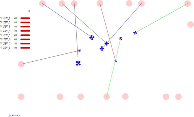
Screenshots of the computer model working are shown in Figures 3 and 4.
Figure 3.
Computer model during the simulation process without any motion control.
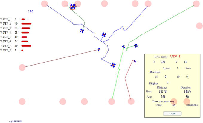
Figure 4.
Computer model during the simulation process with proposed novel INN.
In Figure 3, the drones operate without any motion control, simply taking the shortest path from one point to another. During this movement, they do not perform risk assessments or implement collision prevention strategies. Figure 4 employs the INN immune neural network for motion control. The suggested unsupervised drone control system calculates the collision probability and adjusts movement parameters to minimize it. As a result, the paths of the drones in Figure 4 are not straight, as they are modified to avoid potential collisions.
The database was developed to store parameters of simulation (Table 1) and to save the results of the computer simulations (Table 2).
Parameter
Meaning
XYerr
XY position error -XYerr < err < + +XYerr
Verr
speed error -Verr < err < + +Verr
Rerr
rotation error -Rerr < err < + +Rerr
TXdelay
data transmission delay, ms
Sdelay
own positioning data refresh delay, ms
AreaRate
safety zone area rate proportional to the size
Ap
the magnitude of movement parameter adjustments is determined by the collision probability weight. A higher collision probability weight leads to smaller changes in the movement parameters, while a lower weight results in larger adjustments
Av
speed change weight Av = (1-Ap)/2
Ar
trajectory change weight Ar = (1-Ap)/2
TrLim
maximal number of iterations for the one decision-making process
Sens
collision sensibility
Psens
probability sensitivity
Vlim
maximal speed
Anglim
the maximal possible trajectory change refers to the maximum angle adjustment that can be made to the drone’s flight path
Safedist
the maximum distance to the other drone defines the threshold at which the drone begins crash-prevention actions and calculates the collision probability
Table 1.
Parameters of the computer simulation.
Parameter
Meaning
AvDur
Average duration of one flight
SmDur
The shortest duration of the flight
LngDur
The longest duration of the flight
AvDist
Average distance of one flight
SmDist
The smallest distance of the flight
LngDist
The biggest distance of the flight
Trips
Number of complete trips/flights during simulation
Collisions
Number of collisions during simulation
Table 2.
Computer simulation output data.
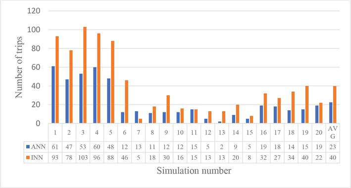
The summarized results of the simulations are presented in Figure 5. In the next subsections, the description of results is done with reference to the simulation numbers. Better results with the higher number of trips done by drones.
The first computer simulation was made without any motion control. All the objects were moving straight from one point to another and back again during the simulation.
The results of computer simulation without any motion control show that 8 drones did an average 419 trips and also 60 collisions are detected during 10 minutes (Figure 5 simulations 1–5).
8. Results of simulations with traditional ANN and new proposed INN without data transmission delays and errors
No data transmission delays and errors were used in these simulations. Other parameters were the same during all simulations (Table 3). A description of the input and output parameters is provided in the Tables 1 and 2.
ID
XYerr
Verr
Rerr
Txdelay
Sdelay
AreaRate
Ap
Av
Ar
TrLim
Sens
Psens
Vlim
Anglim
Safedist
1
0
0
0
0
0
1
0.8
0.1
0.1
50
6
0.1
70
90
150
Table 3.
Input set 1 of parameters for the computer simulation.
The output data shows that the number of collisions was reduced to zero during simulations with the ANN, compared to the simulations without any motion control (Figure 5 simulations 6–10). However, the number of completed trips was much lower (Table 4). For the simulations with the proposed INN, the same parameters were used. As a result, no collisions were detected, and the number of trips increased to an average of 92 trips per 10-minute simulation (Table 4).
9. Results of simulations with traditional ANN and new proposed INN with data transmission delays and without errors
During these simulations, a data transmission delay of 2000 ms and an own positioning data refresh delay of 500 ms were used (Figure 5 simulations 6–10).
On average, 12 trips were completed during simulations with a traditional ANN (Table 5), which is half as many as during simulations with the proposed INN (Table 6). However, collisions were detected in all simulations, indicating that requirements need to be changed and other parameter values must be adjusted to ensure safe driving.
ID
XYerr
Verr
Rerr
Txdelay
Sdelay
AreaRate
Ap
Av
Ar
TrLim
Sens
Psens
Vlim
Anglim
Safedist
2
0
0
0
2000
500
1
0.8
0.1
0.1
50
6
0.1
70
90
150
Table 5.
Input set 2 of parameters for the computer simulation.
10. Results of simulations with traditional ANN and new proposed INN with data transmission delays, without errors, and with improved parameters
An increased value of the parameter “maximal distance till other drone to start crash prevention and to calculate collision probability” was used during these simulations (Figure 5 simulations 11–15).
The output data shows that although the number of trips was reduced, they were safer and without collisions. Moreover, the number of trips was twice as large during simulations with the proposed INN (Tables 7 and 8).
ID
XYerr
Verr
Rerr
Txdelay
Sdelay
AreaRate
Ap
Av
Ar
TrLim
Sens
Psens
Vlim
Anglim
Safedist
3
0
0
0
2000
500
1
0.8
0.1
0.1
50
6
0.1
70
90
500
Table 7.
Input set 3 of parameters for the computer simulation.
Simulation Nr.
System
AvDur
SmDur
LngDur
AvDist
SmDist
LngDist
Trips
Collisions
AVG 11–15
ANN
30
12
59
773
455
1311
7
0
AVG 11–15
INN
32
11
109
726
439
1569
14
0
Table 8.
Simulation results with the parameter set ID 3.
11. Results of simulations with traditional ANN and new proposed INN with data transmission delays and errors
During these simulations, data delays and errors were introduced to replicate the real-time experiment’s conditions (Figure 5 simulations 15–20).
No collisions were detected in any of the simulations. Furthermore, the number of trips completed was almost twice as high during simulations with the proposed INN (Tables 9 and 10).
ID
XYerr
Verr
Rerr
Txdelay
Sdelay
AreaRate
Ap
Av
Ar
TrLim
Sens
Psens
Vlim
Anglim
Safedist
4
10
1
1
100
100
1
0.8
0.1
0.1
100
6
0.5
70
90
500
Table 9.
Input set 4 of parameters for the computer simulation.
Simulation Nr.
System
AvDur
SmDur
LngDur
AvDist
SmDist
LngDist
Trips
Collisions
AVG 16–20
ANN
84
14
398
2118
868
5609
17
0
AVG 16–20
INN
52
11
391
1186
432
6709
31
0
Table 10.
Simulation results with the parameter set ID 4.
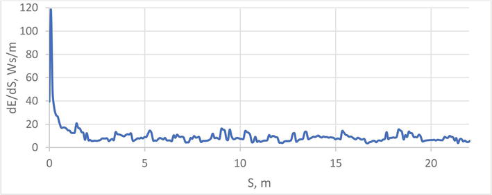
The example of results for energy efficiency control INN is presented in Figure 6.
Figure 6.
Example of energy consumption dE per meter dS during the motion.
Initially, the consumption per meter is higher, but during the self-learning of the immune neural network for energy control the energy consumption per meter is significantly reduced, by choosing the best values of control signals when no risks of collisions are detected.
12. Conclusions
Centralized, decentralized, and distributed control system models were compared. The results of the comparison show that a distributed system is preferable than a centralized or decentralized one. Distributed models are easier to implement, they have less components, they are cheaper for infrastructure owner, and they are not connected to the specific area. They have also decreased time for reaction and decreased risk at system failure. That is why a distributed system structure was used in this research.
The researchers developed and provided a description of the system structure proposed in the study. The microcontroller or embedded computer in each drone performs all the necessary functions. It handles tasks like object recognition, risk assessment, opportunity evaluation, and decision-making regarding movement parameter adjustments. Such a solution helps to minimize data processing time because there is no need to transmit the data to the common center and backward.
In this research, the traditional neural network is included to compare its results with those of the proposed novel INN immune neural network. The objective is to draw conclusions on whether the novel network is better or worse than the traditional one.
A comparison of ANN- and INN- based algorithms was done, considering the impact on traffic safety and necessary time for decision calculation, where INN presents better results described below. Results approve the proposed hypothesis - an immune neural network can make control decisions to prevent drone collisions with better performance than a traditional neural network in this task.
Novel immune neural network machine learning is a suitable method for energy efficiency and collision prevention of autonomous drones. Proposed INN does not need to be trained in advance. Collision probability minimization process can be started even with empty immune memory.
Proposed INN can be used for minimizing the collision probability, improving unsupervised drone safety and faster data processing in real-time conditions with minimal deviation from task performance.
Proposed INN is better than traditional ANN in drone dangerous situation recognition and prevention task, because of reduced calculation time, which leads to the bigger number of safe trips. Results of computer simulations where drones were able to change their speed and trajectory of motion: without data transmission delays and errors, show that the use of INN helps to increase number of trips by 70% compared to the use of traditional ANN; with data transmission delays and inappropriate maximal distance till other drone to start crash prevention show that the use of INN helps to increase number of trips by 92% compared to the use of traditional ANN and to decrease number of collisions by 25% compared to the use of traditional ANN; with data transmission delays and appropriate maximal distance till other drone to start crash prevention show that the use of INN helps to increase number of trips by 100% compared to the use of traditional ANN; with data transmission delays and errors show that the use of INN helps to increase number of trips by 82% compared to the use of traditional ANN.
The theme of cybersecurity and loss of signal or communication was not considered in this research. It is considered as a prospect for future scientific research.
Results of simulations show that the INN reduces the number of iterations and calculation time. It is necessary to analyze whether it will be sufficient for using low-powered systems.
Acknowledgments
This work has been supported by the European Social Fund within Project No 8.2.2.0/20/I/008 “Strengthening of PhD students and academic personnel of Riga Technical University and BA School of Business and Finance in the strategic fields of specialization” of the Specific Objective 8.2.2 “To Strengthen Academic Staff of Higher Education Institutions in Strategic Specialization Areas” of the Operational Program “Growth and Employment”.
References
1.SharkSpotter combines AI and drone technology to spot sharks and aid swimmers on Australian beaches [Internet]. 2018. Available from: http://theconversation.com/sharkspotter-combines-ai-and-drone-technology-to-spot-sharks-and-aid-swimmers-on-australian-beaches-92667
2.Amazon delivered its first customer package by drone [Internet]. 2016. Available from: https://eu.usatoday.com/story/tech/news/2016/12/14/amazon-delivered-its-first-customer-package-drone/95401366/
3.Safran Group [Internet]. 2023. Available from: https://www.safran-group.com
4.Ke R, Li Z, Tang J, Pan Z, Wang Y. Real-time traffic flow parameter estimation from UAV video based on ensemble classifier and optical flow. IEEE Transactions on Intelligent Transportation Systems. 2019;20(1):54-64. DOI: 10.1109/TITS.2018.2797697
5.Rosales C, Gimenez J, Rossomando F, Soria C, Sarcinelli-Filho M, Carelli R. UAVs formation control with dynamic compensation using neuro adaptive SMC. In: Proceedings of the International Conference on Unmanned Aircraft Systems (ICUAS). Atlanta, GA, USA: IEEE; 2019. pp. 93-99. DOI: 10.1109/ICUAS.2019.8798282
6.Ling L, Niu Y, Zhu H. Lyapunov method-based collision avoidance for UAVs. In: Proceedings of the 27th Chinese Control and Decision Conference (2015 CCDC). Qingdao, China: IEEE; 2015. pp. 4716-4720. DOI: 10.1109/CCDC.2015.7162758
7.Liu Z, Chen J, Lan F, Xia H. Methodology of hierarchical collision avoidance for high-speed self-driving vehicle based on motion-decoupled extraction of scenarios. IET Intelligent Transport Systems. 2020;14(3):172-181. DOI: 10.1049/iet-its.2019.0334
8.Wang D, Huo C, Tong Z, Yang Y, Wang Y. Research on vehicle anti-collision algorithm based on fuzzy control. In: Proceedings of the 2019 Chinese Control and Decision Conference (CCDC). Nanchang, China: IEEE; 2019. pp. 2361-2366. DOI: 10.1109/CCDC.2019.8833461
9.Bondarenko A. Development of Knowledge Extraction Methodology from Trained Artificial Neural Networks [Thesis]. Riga: Riga Technical University; 2020
10.Dung N. Developing models for managing drones in the transportation system in smart cities. Electrical, Control and Communication Engineering. 2019;15(2):71-78. DOI: 10.2478/ecce-2019-0010
11.Gorobecs M, Levchenkovs A. Intelligent electric vehicle motion and crossroad control using genetic algorithms. In: Proceedings of the 10th International Conference on Intelligent Technologies in Logistics and Mechatronics Systems (ITELMS). Lithuania, Panevezys: IEEE; 2015. pp. 1-6
12.Sell R, Nikitenko A, Ziravecka A, Berkolds K, Vitols K, Czekalski P. Unmanned Electrical Vehicles and Autonomous System Simulation. Riga: RTU Press; 2021. ISBN 978-9934-22-667-0. e-ISBN 978-9934-22-668-7
13.Haykin S. Neural Networks. A Comprehensive Foundation. Second ed. Upper Saddle River: Prenctice Hall; 1999 ISBN 8120323734, 9788120323735
14.Kim DH, Lee KY. Neural networks control by immune network algorithm based auto-weight function tuning. In: Proceedings of the 2002 International Joint Conference on Neural Networks. IJCNN'02 (Cat. No.02CH37290). Honolulu, HI, USA: IEEE; 2002. pp. 1469-1474. DOI: 10.1109/IJCNN.2002.1007734
15.Mofaddel M, Tavangarian D. A Distributed System with a Centralized Organization. Rostock, Germany; 1997
16.Graybeal P, Franklin M, Cooper D. Principles of Accounting. Volume 2: Managerial Accounting. OpenStax; 2019
17.Dewan R, Pahuja N, Kukreja S. Distributed operating system – An overview. International Journal of Research (IJR). 2014;1(10):539-548
Written By
Mikhail Gorobetz, Leonids Ribickis, Anna Beinarovica and Aleksandrs Kornejevs
Submitted: 21 July 2023Reviewed: 22 July 2023Published: 18 September 2023
 Open access peer-reviewed chapter