Open Access is an initiative that aims to make scientific research freely available to all. To date our community has made over 100 million downloads. It’s based on principles of collaboration, unobstructed discovery, and, most importantly, scientific progression. As PhD students, we found it difficult to access the research we needed, so we decided to create a new Open Access publisher that levels the playing field for scientists across the world. How? By making research easy to access, and puts the academic needs of the researchers before the business interests of publishers.
We are a community of more than 103,000 authors and editors from 3,291 institutions spanning 160 countries, including Nobel Prize winners and some of the world’s most-cited researchers. Publishing on IntechOpen allows authors to earn citations and find new collaborators, meaning more people see your work not only from your own field of study, but from other related fields too.
To purchase hard copies of this book, please contact the representative in India:
CBS Publishers & Distributors Pvt. Ltd.
www.cbspd.com
|
customercare@cbspd.com
The design of concrete structures and elements in Europe and wider is conducted according to EN 1992-1-1. Among other design assumptions, the Eurocode 2 assumes the design value of the modulus of elasticity Es of reinforcing steel to be 200 GPa. However, what happens in the RC beam if the actual modulus of elasticity is significantly reduced. Does it affect the flexural bearing capacity of RC beam and to what extent? Another logical question is how to determine the actual flexural bearing capacity of the RC beam reinforced with reinforcing steel with a reduced modulus of elasticity and which design model to use for such determination. This study tries to answer such questions using an experimental approach and assumed calculation model with a comparison of experimental and calculation results. The experimental research from this showed that test RC beams reinforced by steel with reduced modulus of elasticity have significantly reduced flexural capacity in comparison with the designed flexural capacity of beams reinforced by steel with “normal” modulus of elasticity. In this regard, it is recommended to test the mechanical properties of the steel reinforcement prior to the installation at the site and not to rely on the producer’s factory production control certificate only. Additional issues considered in this research are observed effects of the reduced modulus of elasticity of reinforcing bars to Serviceability Limit States (stress limitation, crack width, and deflection control). Answers to such questions can inform decisions if retrofit is needed, is it feasible and if yes—which retrofit method to be used. This study does not discuss the reasons for the reduced modulus of elasticity in reinforcing steel.
Faculty of Technical Sciences, Department of Civil Engineering, University of Bihac, Bihac, Bosnia and Herzegovina
Aldin Mahmutovic
Faculty of Technical Sciences, Department of Civil Engineering, University of Bihac, Bihac, Bosnia and Herzegovina
*Address all correspondence to: ninsa_d@hotmail.com
1. Introduction
Reinforced concrete is a material widely used for construction all over the world, and there is practically no serious structure, building, or facility that has not been built in reinforced concrete as a whole or in part. Design of load-bearing structures is generally based on the strength of materials, where the homogeneity and isotropicity of the material are assumed. However, concrete is anything but, neither homogeneous nor isotropic. For this reason, the design of concrete structures is so complex.
Concrete is essentially a composite material, and even when reinforced with steel reinforcement with the basic task of taking over the tensile forces in the reinforced concrete element, that compositeness becomes even more pronounced. Each of the concrete ingredients and materials used contributes to the behavior of materials, elements, or the entire structure.
In this sense, the quality control of concrete, both in production and on the construction site itself, in accordance with design assumptions, is well developed both through regulations and standards, as well as their application in a large part of the world.
However, the steel reinforcement is purchased locally on the construction materials market and practitioners are usually satisfied with the manufacturer’s certificates of the steel reinforcement without any further control of steel reinforcement and is installed in accordance with the reinforcement plans from the structural design. However, let us ask a hypothetical question—what happens to the element and the entire reinforced concrete structure if the steel reinforcement does not correspond to the assumptions from the standards or design? What serviceability issues can arise in the case of installation of inappropriate steel reinforcement? Can this cause consequences for the structure, building, or facility, are the deformations in accordance with the expected, is the load-bearing capacity endangered? Can there be serious consequences that will affect the load-bearing capacity and serviceability of the structure? Will it be necessary to retrofit the structure, is it even possible, in what way and how much will it cost? Can the building collapse and under what conditions lead to catastrophic consequences? And finally, the question—whose responsibility, is it? On the other hand, with modern methods of retrofit and strengthening of concrete structures, it is possible to significantly increase the load-bearing capacity of concrete structures by using state-of-the-art materials with respect to all technological processes for their application [1].
This research represents a contribution to the eventual elaboration of the mentioned aspects in the previous paragraph. Essentially, this research deals with the consequences of reinforced concrete construction if steel reinforcement with a reduced modulus of elasticity is installed in an element or structure.
In relation to the modulus of elasticity, the current practice is to assume to be about 200 GPa for all steel grades. However, tensile tests of these steels have consistently shown that the modulus of elasticity varies with grade steel and thickness [2].
There are several methods for determining the modulus of elasticity. The most known methods are mechanical (static and dynamic), acoustic, ultrasonic, resonant, optic, etc. [3, 4, 5, 6]. Mechanical methods are the most compatible for determining the elastic modulus of thin materials such as rods, wires, and fibers [3]. “The mechanically measured Young’s modulus of metals is consistently lower than the physically measured one, particularly after plastic straining. Furthermore, the nominally elastic loading and unloading behavior is not linear; it shows significant curvature and hysteresis. While many reports of this so-called “modulus effect” have appeared, the consistency of the behavior among grades of steel, or within a single grade produced by alternate methods and suppliers, is unknown” [7].
Lems [8] concluded that the mechanically measured Young’s modulus is reduced by plastic straining. The study from Morestin and Boivin [9] showed that materials degraded up to approximately 20% during the first 5% of plastic strain and using the mechanically measured Young’s modulus value. Further research showed similar degradation magnitudes, depending on the material: up to 30% for mild steels [10] and 20% for high-strength steels [10, 11]. Numerous tensile tests of different grade of steel and thickness revealed that the current practice of assuming the same modulus of elasticity value of 200 GPa for all grades and thicknesses of steel may be inaccurate [2].
With the increasing use of a range of high-strength steels and thin steels in the building and construction industry, a good knowledge of the basic mechanical properties of these steels, namely, the yield and tensile strengths, the modulus of elasticity and ductility parameters is needed [2].
The mechanical properties of steel rebars affect the load-bearing capacity of a particular structure [12]. However, there are no or very limited number of theoretical or experimental investigations related to how reduced modulus of elasticity affects the load-bearing capacity of the RC elements. This research is a contribution to this gap.
Experimental comparative research methodology was used in this research. It aimed to determine the effects of the steel reinforcement with reduced modulus of elasticity to the flexural capacity of the RC beams. The comparison was made to the design model according to EN 1992-1-1 [13] with steel reinforcement with a specified modulus of elasticity of 200 GPa.
There are two considered research questions in this study. The first one is does the reduced modulus of elasticity of steel reinforcement affect the flexural and load-bearing capacity of RC beams and how? The second question relates to the failure mode of RC beams reinforced by steel reinforcement with reduced modulus of elasticity.
The findings on these research questions can inform the necessity for further investigation on effects of altered mechanical properties of the applied materials to the behavior of load-bearing elements and structures in serviceability and ultimate limit states, as well as necessity for retrofitting.
The goal of the experimental analysis in this research is to compare the actual flexural capacity and behavior of a reinforced concrete beam in the ultimate limit state, which is reinforced with steel reinforcement with a reduced modulus of elasticity compared to a reinforced concrete beam reinforced with steel reinforcement with a standard modulus of elasticity according to EN 1992-1-1 [13].
3.1 Test samples
The subject of the experimental test is a series with three RC beam samples. The dimensions of the beam were chosen so that they could be adapted to the capabilities and equipment of the laboratory, so it is a small-scale experimental analysis.
The experimental series of beams consists of three reinforced concrete beams with a width of 10 cm, a height of 20 cm, and a length of 140 cm. They are made of concrete C 25/30 and reinforced with ±2 Ø 8 reinforcing steel fyk = 500 MPa (Figure 1).
Figure 1.
Dimensions and reinforcement of test samples (cm).
It should also be noted that the thickness of the concrete cover on the test beams is 1.0 cm. According to EN 1992-1-1 [13] and EN 1992-1-2 [14], this thickness of the concrete cover is not adequate for beams, but it was applied in this research in order to adapt the dimensions of the test beams to the capabilities of the equipment in the laboratory, and in order to increase the flexural capacity of the test samples.
3.2 Production of formwork for test samples
The formwork for the preparation of the samples was made according to Figure 2. Timber formwork consists of three elements:
Formwork bottom 2.7 cm thick, dimensions 150 cm × 50 cm;
Back sides made of planks 2.4 cm thick, 20 cm deep; and
Protection against buckling and dimensional stability of the sides during casting of concrete- lath 3 cm × 5 cm.
Figure 2.
Test samples formwork plan in cm.
According to the formwork plan, the formwork was produced and is displayed in Figure 3.
Figure 3.
Test samples formwork.
3.3 Materials for test samples
According to the experiment design, it was envisioned that test samples will be made from concrete C 25/30. In order to prove the achieved class of concrete, three cube-shaped test samples of 15 × 15 × 15 cm/cm/cm were taken for compression strength testing. After 24 hours of concrete casting, the samples were taken out of the mold and immersed in water for conditioning, where they remained until the compression testing (Table 1).
Designation of test sample
Test sample 1
Test sample 2
Test sample 3
Mean value fcm
Compression strength fci [N/mm2]
31.80
29.60
31.70
31.03
Table 1.
Compressive strength testing results for concrete.
EN 206 [15], Appendix B, Table B1 requires that each individual fci result must be greater than or equal to fck – 4, thus:
In addition, the mean value of the results (fcm) must be equal to or greater than fck + 1, so:
Mean value fcm = 31.03 MPa ≥ (30.0 + 1.0) = 31.0 MPa.
Therefore, according to EN 206 [15] and the criterion of identity, the concrete from which the samples of reinforced concrete beams were made is classified as concrete class C 25/30.
Reinforcing steel (fyk = 500 MPa) was procured locally in the market. As part of this research, the mechanical characteristics of the applied reinforcing steel were tested. From the results, it can be seen that the mean yield stress value of the steel is without large deviations and is 660.33 MPa and is significantly above fyk = 500 MPa. On the other hand, EN 1992-1-1 [13] in Section 3.2.7 (4) specifies that the calculation value of the modulus of elasticity of reinforcing steel of Es = 200 GPa can be assumed. By analyzing the results of the reinforcing steel test, it was established that the mean value of the modulus of elasticity of the applied reinforcing steel is significantly lower and amounts to 127.33 GPa, with minimal deviations from the mean value (125 GPa minimum value and 130 GPa - maximum value), which is significantly lower than the assumption in EN 1992-1-1 [13].
3.4 Production of test samples
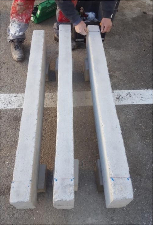
Figures 4 and 5 show the phases of production of RC beam samples. The remaining two series of beams are used for other studies which are not part of this research.
Figure 4.
Phases of production of test samples.
Figure 5.
Produced test samples of beams.
Processed timber was used to produce formwork. The production of test beams was conducted at the local concrete plant by licensed staff. The conditioning of test beams was conducted for 28 days of age, according to the standard specifications for such testing.
3.5 Testing equipment
The following equipment shown in Figure 6 was used during the test:
Hydraulic gantry press;
Digital flexogauge with a resolution of 0.001 mm;
Optical flexogauge with a resolution of 0.01 mm;
Optical magnifier - magnification 200 times.
Figure 6.
Laboratory equipment.
The test equipment, including measuring devices, was calibrated prior to testing, so that the data would be credible.
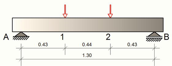
The simulation of the loading of the samples by hydraulic gantry press was done on statical system of a simple beam, with a span of 1.30 m, with concentrated forces in a third of the span according to Figure 7.
Figure 7.
Statical system (dimensions in m).
The load on the beam is applied gradually in increments according to Table 2 up to the sample failure and then the test samples would be unloaded.
Phase
Hydraulic gantry press stress [MPa]
Hydraulic gantry press force [kN]
Maximal shear force Vmax [kN]
Maximal bending moment Mmax [kNm]
0
0.00
0.00
0.00
0.00
1
1.25
2.97
1.48
0.64
2
2.50
5.94
2.97
1.29
3
3.75
8.90
4.45
1.93
4
5.00
11.87
5.94
2.57
5
6.00
14.25
7.12
3.09
6
7.00
16.62
8.31
3.60
7
8.00
19.00
9.50
4.12
8
9.00
21.37
10.69
4.63
9
10.00
23.75
11.87
5.15
10
11.00
26.12
13.06
5.66
11
12.00
28.50
14.25
6.17
12
13.00
30.87
15.44
6.69
13
14.00
33.24
16.62
7.20
14
15.00
35.62
17.81
7.72
15
16.00
37.99
18.90
8.23
16
17.00
40.37
20.18
8.75
17
18.00
42.74
21.37
9.26
18
19.00
45.12
22.56
9.78
19
20.00
47.49
23.75
10.29
Table 2.
Gradual loading plan.
Since the beam has its self-weight, as well as the weight of the apparatus, this constant load cause specific effects, so they also need to be taken into account. The statical system with the self-weight of the beam is shown in Figure 8 and apparatus for load transfer in Figure 9.
Figure 8.
Self-weight of the beam (dimensions in m).
Figure 9.
Apparatus for load transfer (dimensions in m).
Apparatus for load transfer – concentric force G = 0.11 kN.
Self-weight distributed load g:
g=0.10×0.20×1.4×25/1.3=0.54kN/m’E1
Maximal shear force of self-weight and apparatus Vg,max:
Vg,max=0.54×1.3/2+0.11=0.46kNE2
Maximal bending moment of self-weight and apparatus Mg,max:
Mg,max=0.54×1.32/8+0.11×1.3/3=0.16kNmE3
During the test, and for each load increment of the test beams, the deflection is measured with an optical deflection meter with a resolution of 0.01 mm (Figure 10).
Figure 10.
Optical deflection meter during testing measuring deflection.
During the test, the axial deformation at the position of the main longitudinal tensile reinforcement is also measured with a digital flexometer with a resolution of 0.001 mm (Figure 11).
Figure 11.
Digital flexometer meter during testing measuring the axial deformation at the position of the longitudinal reinforcement.
Experienced and licensed engineers and laboratory technicians conducted quality control during the tests.
During the tests in the laboratory, three beams were tested, which were marked as B1, B2, and B3. The test results are presented in the following tables and diagrams.
5.1 Test sample B1
Test sample B1 proved to be the weakest sample in the series. By increasing the bending moment over 3.76 kNm, the first visible cracks appear on the supports. Oblique cracks are also visible, which predominate near the support, which shows that concrete as a material has exhausted its shear capacity. Further increase of the bending moment leads to their propagation and expansion. The loss of flexural bearing capacity of the Test Sample B1 occurs at a bending moment of 5.31 kNm. Namely, then the strain of the reinforcement is significantly over 2‰ (Figure 13), which means that the stress in the reinforcement has reached the tensile yield limit, and after that the reinforcement strain suddenly increases. After unloading, the residual deflection is 3.06 mm (Figures 12 and 13), and the plastic strain of the reinforcement is 0.353‰ (Table 3).
Figure 12.
Diagram of deflections for test sample B1.
Figure 13.
Diagram of strains for test sample B1.
Test sample B1
Phase
Shear force
Bending moment
Deflection
Axial deformation
Strain ε
[kN]
[kNm]
[mm]
[mm]
‰
0
0.46
0.16
0.00
0.000
0.000
1
1.94
0.80
1.00
0.122
0.406
2
3.43
1.45
1.32
0.162
0.540
3
4.91
2.09
2.02
0.205
0.683
4
6.40
2.73
2.66
0.284
0.946
5
8.04
3.25
3.35
0.360
1.200
6
8.77
3.76
4.16
0.438
1.460
7
9.96
4.28
4.88
0.526
1.753
8
11.15
4.79
5.82
0.613
2.043
9
12.33
5.31
7.12
0.875
2.916
Load relief
0.46
0.16
3.06
0.106
0.353
Table 3.
The test results for test sample B1.
5.2 Test sample B2
Test Sample B2 shows more favorable behavior in terms of the appearance of the first cracks, which occur at a bending moment of 4.28 kNm, when the first cracks A, B, C, and D appear (Figure 14). By increasing the bending moment to 4.69 kNm, oblique cracks F, G appear and H (Figure 14), which show that the concrete has lost its shear capacity, and their further propagation creates concrete struts. Flexural failure of the beam occurs at a bending moment of 5.31 kNm. After unloading, the residual deflection is 3.35 mm (Figure 15 and Table 4).
Figure 14.
Diagram of deflections for test sample B2.
Figure 15.
Diagram of strains for test sample B2.
Test sample B2
Phase
Shear force
Bending moment
Deflection
Axial deformation
Strain ε
[kN]
[kNm]
[mm]
[mm]
‰
0
0.46
0.16
0.00
0.000
0.000
1
1.94
0.80
0.95
0.123
0.410
2
3.43
1.45
1.35
0.168
0.560
3
4.91
2.09
2.03
0.204
0.680
4
6.40
2.73
2.70
0.288
0.960
5
8.04
3.25
3.20
0.359
1.196
6
8.77
3.76
3.90
0.449
1.496
7
9.96
4.28
4.65
0.521
1.736
8
11.15
4.79
5.49
0.616
2.053
9
12.33
5.31
5.87
0.879
2.930
Load relief
0.46
0.16
3.35
0.140
0.466
Table 4.
The test results for test sample B2.
5.3 Test sample B3
Test Sample B3 showed similar results to beam B2. The results of the experimental analysis of Test Sample B3 are presented in tabular (Table 5) and graphical form (Figures 16 and 17). The failure of the Test Sample B3 occurs when a bending moment of 5.31 kNm is applied. After unloading, the residual deflection is 3.16 mm, and the plastic strain of the reinforcement is 0.446‰. Based on the obtained experimental results, an experimental flexural capacity of all test samples is 5.31 kNm.
Test sample B3
Phase
Shear force
Bending moment
Deflection
Axial deformation
Strain ε
[kN]
[kNm]
[mm]
[mm]
‰
0
0.46
0.16
0.00
0.000
0.000
1
1.94
0.80
0.32
0.117
0.390
2
3.43
1.45
0.73
0.158
0.526
3
4.91
2.09
1.14
0.213
0.710
4
6.40
2.73
2.73
0.303
1.010
5
8.04
3.25
3.38
0.363
1.210
6
8.77
3.76
4.10
0.453
1.510
7
9.96
4.28
4.88
0.483
1.610
8
11.15
4.79
5.68
0.613
2.043
9
12.33
5.31
6.41
0.873
2.910
Load relief
0.46
0.16
3.16
0.134
0.446
Table 5.
The test results for test sample B3.
Figure 16.
Diagram of deflections for test sample B3.
Figure 17.
Diagram of strains for test sample B3.
5.4 Width of cracks
One of the basic assumptions in the design of reinforced concrete structures in flexure is that the concrete does not take over the tensile forces and that all tensile stresses are taken over by the steel reinforcement. Cracks occur when actual tensile stresses exceed the tensile strength of concrete. In general, cracks in the tension zone of reinforced concrete do not affect the flexural capacity of the structure to a large extent. On the other hand, when designing reinforced concrete structures to serviceability limit states (SLS), the width of cracks is also considered, especially in facilities where width of cracks affects the corrosion of reinforcement, external appearance, and impermeability to liquids or gases. The limit width of cracks for reinforced concrete structures ranges from 0.3 to 0.4 mm, depending on the exposure class of the concrete. In this research, during the experimental analysis, crack propagation was also observed, considering that it was feasible, although it was not the primary goal of the research.
The widths of the cracks in the concrete were observed using an optical magnifier with a magnification of 200 times. The following figure shows the measured crack widths at a bending moment of 3.76 kNm.
Figure 18 shows that the width of the cracks is up to 0.30 mm at a bending moment of 3.76 kNm. However, by increasing the bending moment to 4.28 kNm, the cracks widen from 0.41 to 0.85 mm, which is shown in Figure 19.
Figure 18.
Measured crack widths at a bending moment of 3.76 kNm (in mm).
Figure 19.
Measured crack widths at a bending moment of 4.28 kNm (in mm).
6. Determination of flexural capacity of beams with modulus of elasticity of steel reinforcement Es = 200 GPa
The determination of the flexural capacity of the beams is conducted using a rectangular stress distribution in the concrete section, according to EN 1992-1-1, Section 3.1.7 (13) (Figure 20).
Figure 20.
Rectangular stress distribution in the concrete section [16].
The determination of flexural capacity assumes a system in equilibrium. In this case, the compressive force in the concrete and the tensile force in reinforcement are equal.
Fcc=FStE4
Then, the compressive force in concrete is:
Fcc=σc·AE5
where
σc - compression stress in concrete;
A - concrete area in compression.
Compression stress in concrete is:
σc=α·fckγc=0.85·fck1.5E6
while concrete area in compression is:
A=b·sE7
and tensile force is calculated as:
FSt=σs·AsE8
where:
σs - tensile stress in reinforcement.
As - cross-sectional area of reinforcing steel.
Tensile stress in reinforcement is:
σ=fykγs=fyk1.15E9
while flexural capacity is:
MRd=Fst·zE10
In this specific case of the cross section of a reinforced concrete beam with dimensions of width 100 mm and height 200 mm, made of concrete class C 25/30, reinforced with longitudinal reinforcement in both zones 2 Ø 8, of reinforcing steel fyk = 500 MPa, the calculation of the flexural capacity is as follows:
Fcc=FStE11
0.85·fck1.5·b·s=fyk1.15·AsE12
0.567fck·b·s=0.87fyk·AsE13
Based on that, the height of the compressive concrete block is:
7. Model for determining the flexural capacity of RC beams reinforced by steel with reduced modulus of elasticity
Table 6 displays an overview of the experimentally recorded axial deformations of the test beams with the mean value of strains depending on the phase of loading of test beams to the failure.
Phase
Shear force [kN]
Bending moment [kNm]
Axial deformation
Mean strain ε ‰
Test Sample B1 [mm]
Test Sample B2 [mm]
Test Sample B3 [mm]
0
0.46
0.16
0.000
0.000
0.000
0.000
1
1.94
0.80
0.406
0.410
0.390
0.402
2
3.43
1.45
0.540
0.560
0.526
0.542
3
4.91
2.09
0.683
0.680
0.710
0.691
4
6.40
2.73
0.946
0.960
1.010
0.972
5
8.04
3.25
1.200
1.196
1.210
1.202
6
8.77
3.76
1.460
1.496
1.510
1.489
7
9.96
4.28
1.753
1.736
1.610
1.700
8
11.15
4.79
2.043
2.053
2.043
2.047
9
12.33
5.31
2.916
2.930
2.910
2.919
Table 6.
Comparison of experimental test results for axial deformation.
Data on strains are also shown in the diagram in Figure 22, which shows a significant concurrence of experimental strains for all three samples of reinforced concrete beams.
Figure 22.
Concurrence on experimental strains for all three samples of test reinforced concrete beams.
Considering the mean strain was 2919‰ at the moment of failure of test beams, and the mean value of the modulus of elasticity of the reinforcing steel with reduced modulus of elasticity (127.33 GPa), the tensile stress in the reinforcing steel was:
σs=Esmean·ϵmean=127.33·2.919·10−3=371.68MPaE17
Furthermore, this means that the tensile force in the steel reinforcement is:
Fst=σs·As=371.68·100.48·10−3=37.346kNE18
and based on the equilibrium of forces in the cross section
Fcc=FStE19
that is
0.567fck·b·s=37.346kNE20
so, the depth of the compression stress block of concrete s is
s=Fst0.567fck·b=37.3460.567·25·100=26.35mmE21
and the arm of internal forces is equal to:
z=d−0.5·s=180−0.5·26.35=166.82mmE22
Based on this, the compression stress in concrete is:
which exhausted the compression capacity of the concrete, so the compression stress block of the concrete fails by brittle fracture through concrete, and confirmed by experiment, so there is a complete concurrence of the experimental and calculated data on the flexural bearing capacity of the section reinforced by steel with reduced modulus of elasticity.
The experimental research showed that test RC beams reinforced by steel with reduced modulus of elasticity (127,33 GPa) have reduced flexural capacity in comparison with designed flexural capacity of beams reinforced by steel with “normal” modulus of elasticity (200 GPa) by 26.15% (Table 7).
Experimental flexural capacity for test beams with reduced modulus of elasticity [kNm]
Designed flexural capacity for test beams according to EN 1992-1-1 [kNm]
Percentage [%]
5.31
7.19
73.85
Table 7.
Comparison of experimental flexural capacity test results for test beams with reduced modulus of elasticity and designed flexural capacity for test beams according to EN 1992-1-1.
The experiment showed that reduced modulus of elasticity of steel in reinforced concrete beams leads to faster increase in the strain of the reinforcement, which additionally leads to the displacement of the neutral axis toward the extreme compression fiber of the section, reducing the compression stress block of the concrete, and as a result of the equilibrium of forces in the cross section, consequently leads to the brittle failure of the concrete, which reduces the flexural capacity of the cross section in comparison to the designed flexural capacity according to EN 1992-1-1. This is especially pronounced in the case of reinforced concrete beams with smaller dimensions of cross section.
The results of this research can be applied if reinforcing steel with a reduced modulus of elasticity has already been embedded into the reinforced concrete beams, all with the aim of determining the flexural capacity of the already constructed beam, as the basis for concluding whether it is necessary to repair or rertrofit the concrete beam or even the entire structure.
The calculation model proposed in this research can also be used for further research for beams with larger cross-sectional dimensions and a larger amount and diameter of embedded steel reinforcement with a reduced modulus of elasticity, as well as for RC slabs in order to confirm or modify the model.
The reasons for the presence of steel reinforcement on the local markets with a reduced modulus of elasticity are not discussed here. However, the installation of this type of steel reinforcement in concrete elements without prior insight into the mechanical properties of the steel reinforcement before installation can lead to serious consequences in the service of the building or facility. In this sense, in areas and countries with inadequate control of the market for construction materials, it is necessary to examine the mechanical properties of the steel reinforcement before installation and make sure that it corresponds to the mechanical properties required by the design. In this sense, when it comes to steel reinforcement, it is not enough to check the yield strength of the steel reinforcement only, but also other specified mechanical properties, especially the modulus of elasticity, which this research has shown.
References
1.Dzidic S, Mahmutovic A. Analysis of the possibilities for retrofit of RC beams by traditional and modern methods. In: Proceedings of the 18th International Symposium of Macedonian Association of Structural Engineers MASE 18. Ohrid, North Macedonia: Macedonian Association of Structural Engineers; 2019. pp. 270-279. ISBN 978-608-4510-36-9
2.Mahendran M. The modulus of elasticity of steel - Is it 200 GPa? In: Thirteenth International Specialty Conference on Cold-Formed Steel Structures. St. Louis, Missouri, USA: Missouri University of Science and Technology; 1996
3.Miljojkovic J et al. Determining elastic modulus of the material by measuring the deflection of the beam loaded in bending. Technical Gazette 24. 2017;4:1227-1234. DOI: 10.17559/TV-20170609133537
4.Radovic E, Lara-Curzio E, Riester L. Comparison of different experimental techniques for determination of elastic properties of solids. Materials Science and Engineering. 2004;368(1-2):56-70. DOI: 10.1016/j.msea.2003.09.080
5.Bamber MJ, Cooke KE, Mann AB, Derby B. Accurate determination of Young’s modulus and Poisson’s ratio of thin films by a combination of acoustic microscopy and nanoindentation. Thin Solid Films;398-399:299-305. DOI: 10.1016/S0040-6090(01)01341-4
6.Rho JY, Ashman RB, Charles HT. Young’s modulus of trabecular and cortical bone material: Ultrasonic and microtensile measurements. Journal of Biomechanics. 1993;26(2):111-119. DOI: 10.1016/0021-9290(93)90042-D
7.Zhong C, Umesh G, Jinwoo L, Wagoner RH. Variation and consistency of Young’s modulus in steel. Journal of Materials Processing Technology. 2016;227:227-243. DOI: 10.1016/j.jmatprotec.2015.08.024
8.Lems W. The Change of Young’s Modulus after Deformation at Low Temperature and its Recovery”, Ph.D Dissertation. Delf, Netherlands: Delft University of Technology; 1963
9.Morestin F, Boivin M. On the necessity of taking into account the variation in the young modulus with plastic strain in elastic-plastic software. Nuclear Engineering and Design. 1996;162(1):107-116. DOI: 10.1016/0029-5493(95)01123-4
10.Yoshida F, Uemori T, Fujiwara K. Elastic-plastic behavior of steel sheets under in-plane cyclic tension–compression at large strain. International Journal of Plasticity. 2002;18(5–6):633-659. DOI: 10.1016/S0749-6419(01)00049-3
11.Cleveland RM, Ghosh AK. Inelastic effects on springback in metals. International Journal of Plasticity. 2002;18(5–6):769-785. DOI: 10.1016/S0749-6419(01)00054-7
12.Shayan JA, Peiris R, Coorey RV. Study of elastic properties of reinforcing steel bars. In: Proceedings of the Technical Sessions. Vol. 26. Sri Lanka: Institute of Physics; 2010. pp. 67-74
13.EN 1992-1-1:2004 Eurocode 2. Design of concrete structures. In: Part 1-1: General Rules – Structural Fire Design and Rules for Buildings. Avenue Marnix 17, B-1000 Brussels, Belgium: CEN European Committee for Standardization, Management Centre; 2004
14.EN 1992-1-2:2004. Eurocode 2, Design of concrete structures. In: Part 1-2: General Rules – Structural Fire Design. rue de Stassart, 36 B 1050 Brussels, Belgium: CEN European Committee for Standardization, Management Centre: Management Centre; 2004
15.EN 206:2013. Concrete-specification, performance, production and conformity. In: CEN European Committee for Standardization. Avenue Marnix 17, B-1000 Brussels, Belgium: CEN-CENELEC Management Centre; 2013
16.Mosley B, Bungey J, Hulse R. Reinforced concrete design to Eurocode 2 - seventh edition. In: Palgrave Macmillan in the UK. Hampshire RG21 6XS, UK: Palgrave Mac-Millan; 2012. ISBN-13: 978–0–230–30285–3
Written By
Sanin Dzidic and Aldin Mahmutovic
Submitted: 08 June 2023Reviewed: 19 June 2023Published: 06 November 2023
 Open access peer-reviewed chapter