Open Access is an initiative that aims to make scientific research freely available to all. To date our community has made over 100 million downloads. It’s based on principles of collaboration, unobstructed discovery, and, most importantly, scientific progression. As PhD students, we found it difficult to access the research we needed, so we decided to create a new Open Access publisher that levels the playing field for scientists across the world. How? By making research easy to access, and puts the academic needs of the researchers before the business interests of publishers.
We are a community of more than 103,000 authors and editors from 3,291 institutions spanning 160 countries, including Nobel Prize winners and some of the world’s most-cited researchers. Publishing on IntechOpen allows authors to earn citations and find new collaborators, meaning more people see your work not only from your own field of study, but from other related fields too.
To purchase hard copies of this book, please contact the representative in India:
CBS Publishers & Distributors Pvt. Ltd.
www.cbspd.com
|
customercare@cbspd.com
The satisfactory design of the components is highly dependent on the adequate knowledge of the material behavior and operational conditions. For the structures under earthquakes, often this information is not available, is incomplete or inaccurate, and leads to increases the risk of the possible failures. The extensive brittle fracture of steel structures during the Northridge earthquake (USA, 1994) and Kobe earthquake (Japan, 1995) highlighted many of these deficiencies. The investigations have shown that the failures were caused by combination effects of high strain rate, welding defects, welding residual stress, and seismic loads. In this chapter, the effects of strain rates on mechanical properties of steel materials have been discussed. Welding defects act as cracks and cause the structures to fail at loads lower than design stress. Thus, the issue has been evaluated from the view point of failure mechanics. Welding processes produced residual stresses in the weldments. These regions have higher stresses triaxiality and will be prone to brittle fracture. Therefore, the role of residual stresses in the failure of steel structures is well expressed. The contents given in this chapter can be of great help in preventing the failure of structures during an earthquake and the occurrence of human and financial losses.
Department of Materials Science and Engineering, School of Engineering, Shiraz University, Shiraz, Iran
Abolghasem Dehghan
Department of Materials Science and Engineering, School of Engineering, Shiraz University, Shiraz, Iran
*Address all correspondence to: ar.khalifeh@spc.co.ir
1. Introduction
An earthquake is an unexpected, unpredictable and uncontrollable natural event that occurs in earthquake zones. High loading rate, load application rate 0.1–1/s, changes the mechanical behavior of structural steels. This makes the used metal structures susceptible to brittle fracture and causes many human and financial losses [1, 2, 3, 4, 5, 6, 7].
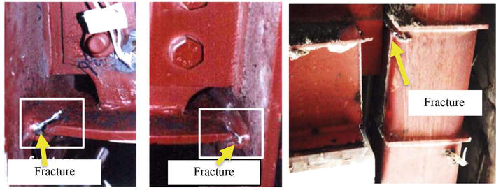
If a structure can withstand large inelastic deformation change, without instability, it is said that it has shown ductile behavior. Design engineers believe that by choosing materials and connections with high flexibility and proper strength, fracture caused by earthquakes can be prevented. Many buildings have been designed and built based on this vision. But extensive brittle fracture during two earthquakes in 1994 in Northridge, America and 1995 in Kobe, Japan cause doubt on this idea [8, 9]. Many cases of such unpredictable brittle fracture have been reported in the lower-flange welds of steel moment resistant frames (WSMFs) as it is seen in Figures 1 and 2 [12, 13]. WSMFs are often constructed using large rolled sections of A36 (beams) and A572 (columns) steel with flux-core field welds (E70T-4) utilized for transferring the primary load [14]. This prompted the idea of new research programs to study the causes of these fractures and to propose needed changes in design and construction procedures [12, 15, 16].
Figure 1.
Example of steel structural failure due to earthquakes [10].
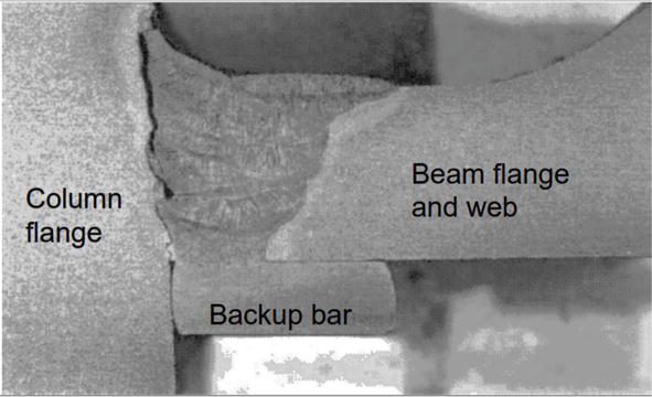
Figure 2.
Photograph of a typical brittle fracture in steel structures [11].
Comprehensive and extensive field and laboratory studies have been conducted regarding the causes of fracture of structures during the two events of Northridge and Kobe earthquakes. The results of the investigations showed that the unexpected and brittle failures in the steel structures during earthquake dynamic loadings were caused by factors such as high strain rate, welding defects, improper connection design, low toughness of the materials used, and seismic loads [6, 16, 17, 18, 19, 20, 21]. The residual stress caused by welding is another important factor involved in fracture of structural steels under earthquake type dynamic loadings [22, 23, 24, 25]. The extent of residual stresses can sometimes reach the yield stress of the material [26]. Therefore, the effect of the presence of residual stresses should also be considered in the fracture studies of steel structures.
In this chapter, the earthquake type dynamic loading is first introduced. Then, the effects of high strain rate on mechanical properties of structural steels are expressed. In next step, the effects of welding defects on fracture behavior of steel structures are discussed using fracture mechanic criteria’s. Finally, the residual stresses and their effects are explained in detail.
Many studies have been done to determine the plasticity characteristics metals at high strain rates. This information is vital in the performance of structures in earthquake and impact conditions [27, 28]. The strain rate, ε̇is defined as follows:
Increasing the strain rate causes the yield point to be observed in steels that do not have a yield point in the static state. For most materials, increasing the strain rate causes an increase in flow stress. The amount of increase depends on the type of material and temperature. For most materials, the effect of strain rate on the flow stress curve, σ, at a constant strain and temperature can be described by a power expression [27, 29]:
σ=Cε̇mE2
where σ is stress, ε̇ is strain rate, and m is called strain rate sensitivity.
Kaufman and Chang have estimated that in the absence of sources of stress concentration, the value of the nominal strain rate (ε̇) for welded joints during an earthquake is in the range of 0.01 to 1/s [30, 31]. This amount of strain rate is 1000 to 10,000 times higher than the quasi-static laboratory conditions. Meanwhile, the presence of stress concentration in front of a crack in the weld of the structure can increase the strain rate to 0.05 to 1/s on the local volume of the material. This amount of strain rate increases the flow stress and reduces the fracture toughness of steel structures and welds and facilitates the conditions of brittle failure (Figure 3) in welded joints [32].
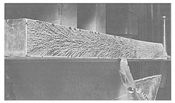
Figure 3.
Typical photograph of a typical brittle fracture in steel structures.
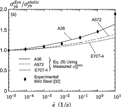
In general, the yield stress of structural steels increases with increasing the strain rate and decreasing temperature [27]. The study of the effect of strain rate on the flow properties of three main types of materials used in structures (A36 beams, A572 columns and E70T-4 welds) was done by Kaufman, Fisher Rolf and Barson (Figure 4) [21]. Accordingly, the lower strength A36 material exhibits the most strain sensitivity compares with higher strength steels grades such as A572 steel and E70T-4. The results shown in Figure 4 are based on measured σysstaticby Kaufman and Fisher and the empirical model (Eq. (3)) provided by Rolf and Barson [11].
Figure 4.
Effects of strain rate on the yield stress of structural steel connections [32, 33].
where σysdyn is the static yield strength at room temperature (MPa), T (°C) and ε̇ refers to the temperature and strain rate of interest, respectively.
According to Figure 4, For A36 steel the yield strength increases by 45% at the strain rate of 1/s and by 65% at the strain rate of 10/s. For A572 steel, a 40% increase in yield strength has been observed for a strain rate of 10/s. This sensitivity value for the weld metal obtained from E-70 T-4 with higher strength than A36 and A572 reaches 25% at a strain rate of 10 seconds, which is a much lower value [32].
2.1 Mechanism
The increase in yield strength of steels due to the increase of strain rate can be described using dislocations theories. The equation for the movement dependence of dislocations on the strain rate is considered as follows [27, 34].
ε̇=ρbv¯E4
where ρ is the density of dislocations, v¯is the average velocity of dislocations and b is the Burgers vector. On the other hand:
v¯∝τmE5
where τ is the shear stress and m is a constant whose value is equal to 35 for iron [27, 34]. In low carbon steels, the dislocations are locked with carbon and nitrogen in the structure. The only way for ρbv¯to adapt to the imposed strain rate is to increase v¯. According to Eq. (5), this state requires applying high stress which lead to increasing the yield stress [27, 34].
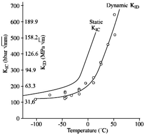
Research has shown that the increasing strain rate also affects the fracture toughness of materials [35, 36]. The graph of the effect of strain rate on the fracture toughness of a steel is given in Figure 5. As it can be seen in the picture, with the increase in loading rate, the temperature of the transition from ductile to brittle of steels has shifted to higher values. This means that the brittle failure of the material under dynamic loads occurs at a higher temperature [35].
Figure 5.
The effect of loading rate and temperature on fracture toughness of a carbon steel material [35].
During an earthquake fire may also occur. In a fire, the high thermal conductivity of steel can spread the heat in the steel structure from a local part to the whole structure in a short time. The mechanical properties of steel structure members will be affected by high temperature impressively. This may have caused numerous economic losses and casualties. Yet, when the fire is extinguished, some fire-affected structural steels may still be used, and what determines they are reusable or not is whether their residual mechanical properties meet the engineering requirements. Therefore, it is of great importance to study the post-fire mechanical properties of structural steels [37, 38]. An equation is proposed by Johnson-Cook, which well express the simultaneous effect of temperature and strain rate on flow stress behavior can be used [39, 40]:
σ=A+Bεn1+Clnɛ̇∗1−T∗mE6
where σ is the stress, ε is the plastic strain, m is the sensitivity coefficient to the strain rate, A, B, C are the constants of the material. The values of ɛ̇∗ and T∗m are expressed as follows:
ɛ̇∗=ɛ̇ɛ̇0andT∗=T−T0Tm−T0E7
where Tm is the melting point of the material, T0 is the ambient temperature, ɛ̇0 is the static strain rate and ɛ̇∗is the dynamic strain rate.
3. Effects of welding defects and fracture mechanic
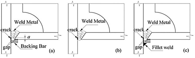
Welding defects are among the important factors of structural failure under earthquake loads [17, 31, 41, 42]. The most important welding defect of welded joints is the incomplete penetration defect, which occurs due to insufficient penetration of the molten welding metal in the root pass. The factors that produce this defect are improper adjustment of welding parameters, improper connection design, and the use of back strips [10]. The location of this defect is shown schematically in Figure 6.
Figure 6.
Schematic of defects in beam-to-column welding connection. (a) Cracks in the beam-to-column connection with the presence of backing strip, (b) crack in connection without backing bar, (c) connection with backing bar and corner welding [10].
Generally, fracture of ductile steels characterized by the nucleation, growth and coalescence of microvoids [27, 43]. The welding defects has formed during the construction of steel structures act like a notch. The presence of the notch in a steel material creates the triaxial state of stress at the site of failure initiation. The triaxiality strongly affects the ductile fracture of steels. The triaxiality is measured as the ratio of hydrostatic tension or mean stress σm to von Misses effective stress σe [43]. Rice and Tracy showed that the rate of change of the mean hole radios R strongly depends upon the stress triaxiality [44]:
dRR=0.28dεexp3σm2σeE8
Where dR is the change in hole radius for a given increment of plastic strain dε. This means that the radius of voids on the fracture surface of a ductile steel increases with increasing triaxiality and the fracture surface will be similar to a brittle fracture mode [44].
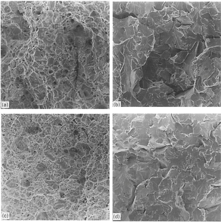
In steel structures and in the conditions of dynamic loads of an earthquake, the simultaneous effect of notch and load application rate is encountered. Mirza et al. [43]. conducted a series of tensile test on notched milled steel samples at different strain rates and discussed the dependence of the failure mode on notch and strain rate. Fractographic examination of the fractured surfaces using scanning electron microscopy for 4 and 0.5 mm notch profiles tested at high rates (3 × 10³ s˗1) and quasi static rates is shown in Figure 7. The 4 mm notch specimen for both strain rate shows a dimple fracture surfaces representing ductile fracture (Figure 7a and c) whereas for 0.5 mm notch (severe condition)the surface displays flat facet containing large multiple cracks, representing a brittle fracture mode (Figure 4b and d). Summary results of fractography examination for mild stees are given in Table 1 [43]. Dependance of the fracture mechanism on the notch radios and strain rate can be clearly seen in the table. The results of the table show a stronger dependence of the failure mode on the notch severity compared to the strain rate.
Figure 7.
SEM image of a mild steel, (a) and (b) 4 and 0.5 mm notch specimen tested at 10 ms˗1 (c) and (d) 4 mm and 0.5 mm notch specimen tested at quasi-static state [43].
Notch radius(mm)
2.5 × 10³ s˗1
3.5 × 10² s˗1
8 × 10˗2s˗1 Quasi-static
4
D
D
D
2
B
D
D
1
B
B
D
0.5
B
B
B
Table 1.
Variation of failure mode from ductile to brittle for a mild steel [43].
D = ductile fracture; and B = brittle fracture.
By using the science of fracture mechanics in the design of structures, assuming the presence of cracks which is inevitable, the conditions can be advanced in such a way as to prevent the premature brittle failure and occurrence of severe losses caused by earthquakes [24, 45, 46, 47]. In the theory of fracture mechanics, a parameter is introduced as stress intensity factor, which has the following relationship with stress,σ, and defect length a [48, 49]:
KI=fgσπaE9
f(g) is a function of the geometry of the part and the crack.
According to this criterion, failure occurs when the value of KI reaches the critical value of KIC. The KIC is called fracture toughness of material. It is a material property in the same sense as that yield strength [50]. As mentioned above, the fracture toughness is also affected by the strain rate where its value decreases at high strain rates (Figure 5). The value of stress intensity factor can be measured using standard samples. In France, the NFA 03–180 standard specifies the necessary conditions for performing the required tests to determine the KIC value of steel structures [35, 45, 51]. It is worth mentioning that steel structures are usually made of low carbon and low alloy steels. Using the critical stress intensity factor for this group of materials causes many errors. Therefore, this criterion can only be used for them at low temperatures and where the material is in a brittle state. To solve this problem, modeling and two-dimensional and three-dimensional finite element methods have been used to evaluate the failure of structural steels and their connections in higher temperatures [24, 32, 47, 52].
In Eq. (9) determining the f(g) function is an important topic in fracture mechanics and has been determined for many parts with different geometries and cracks. In cases where this function is not known, the stress intensity factor can be determined using numerical methods. Here are some situations that are investigated in the field of steel structures that are the subject of this research.
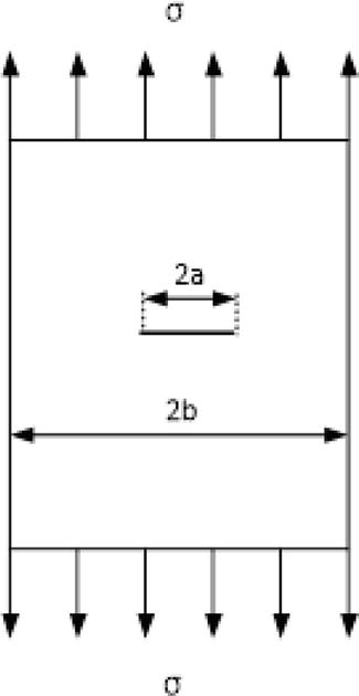
The stress intensity factor for a plate with a large width and a central crack of length 2a (shown in Figure 8) is expressed according to Eq. (10) [49].
Figure 8.
A plate with a limited width has a central crack.
K=σπaE10
If the width of the sheet is limited and equal to 2b, the correction factor should be considered so that the effect of the stress on the edges of the sample in the stress distribution of the crack tip can be included in the relationship of the stress intensity factor. In this case, to Eq. (10) will be as follows [49]:
KI=σπa2bπatanπa2bE11
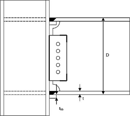
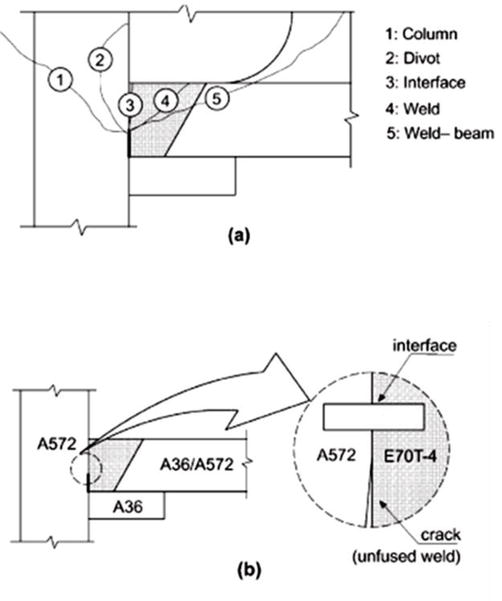
Connecting beam to column is a very common connection in steel structure buildings. Numerous defects in the joint have been the cause of cracking and failure of steel structures in recent earthquakes [6, 17, 18, 19, 53, 54]. Examples of these fractures are shown in Figures 1 and 2. Due to the complexity, the evaluation of the failure conditions of the beam-column joint should be done using finite element methods. Here one of the presented models is introduced. The model is based a type of connection design used in structures before the Northridge earthquake [22]. This design method is shown in Figure 9. Investigations have shown many failures in the lower flange part of these connections. It was easily determined that the origin of these cracks was the lack of sufficient penetration of the weld, which occurred at the root pass with a small radius as shown in Figure 10. The radius of these fine defects is in the range of micrometers, which can be considered and modeled as a crack.
Figure 9.
A schematic of the beam-to-column connection design before the Northridge earthquake [22].
Figure 10.
(a) Schematic of beam and column failure of structures due to earthquake (The origin of the defect is lack of sufficient penetration), (b) Bimaterial interface at the weld–column fusion line [14].
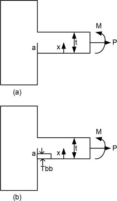
In this model, the crack of the bottom flange of the beam to the column is considered as an edge crack like the one shown in Figure 11a. The stress intensity factors are defined as the following relations depending on the geometry of the crack and the way of loading [22]:
Figure 11.
(a) Schematic of beam-to-column connection under load P and moment M, and (b) showing the same conditions with the presence of a back strip.
Kt=σtπaQYtE12
Kb=σbπaQYbE13
where, parameters σt and σb are reference stresses for tension and bending, respectively. Yt,Yb and Q are stress magnification factors which are defined as the following relationships:
where c is the half crack width. This particular dimension of the crack, which is not seen in Figure 11a, represents its out-of-plane dimension. It is worth mentioning that in the case that the external moment M is also applied, the total stress intensity factor is given as follow [22]:
K=M2IπaQD−tYt+tYbE17
In this relation, I is the second moment of area of beam section, D is the depth and t is the flange thickness. In the meantime, when the back strip is used (Figure 11b), the conditions become more critical, so Yt and Yb are multiplied by the Y11.12 factor. Where Y1 can be calculated from the following equation:
One of the main problems of metal structures is residual stress and distortion caused by localized heat during welding [26, 55]. Residual stresses are the stresses that exist in a body when external loads are removed. These stresses are also called internal stresses in some cases. The risk of brittle fracture in welded structures generally increases in the presence of residual stresses. Panontin et al. show that residual stress can increase the local stress triaxiality ahead of the axial crack front in a cylindrical pressure vessel [56]. The increased triaxiality caused by residual stress can transform a low-constraint structural configuration into a higher constraint (more sever) leading to cleavage fracture at a lower load level [56]. Zhang and Dong [57] and Matos and Dodds [23] found that residual stress alone consume approximately 30% of the available fracture toughness (about 65 MPam) for connection welds utilizing E70T-4 electrodes [21].
Residual stresses are caused by various factors such as mechanical work and welding in parts [22, 58, 59]. There are many factors that are effective in the formation of residual stresses. These parameters include design parameters, material parameters and manufacturing parameters. Design parameters include how to connect components. Material parameters include base metal and weld metallurgical conditions. Welding parameters include welding method, input heat, preheating, and how to restrain components during welding [60].
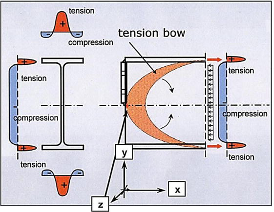
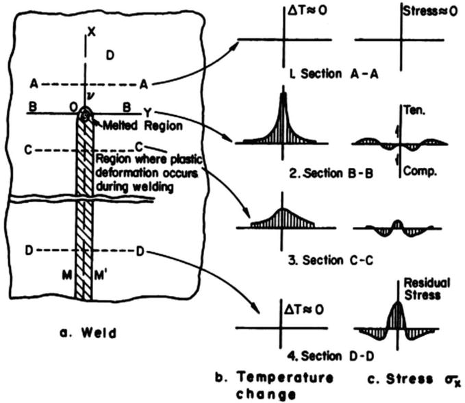
In welding processes two factors are determined. Firstly, the welding residual stress by cause of temperature changes during welding. Second, in some steel grades, the solid-state austenite to martensite transformation in the time of cooling generates a significant value of the residual stresses [61, 62]. The former case is caused by non-uniform temperature changes in the body and are often known as thermal stresses. In fact, during the welding operation, the contraction and expansion of the weld metal and the base metal near the weld metal due to heating and cooling are restrained by the base metal away from the weld metal (Figure 12). Its result is the generation of tensile residual stresses in the weld and compressive residual stresses in the base metal away from the weld [63].
Figure 12.
Distribution of residual stresses in a rolled steel ‘I’ beam with a welded end-plate [63].
Residual stresses caused by welding are applied both longitudinally and transversely to the weld and the area affected by the weld. Meanwhile, the dimensions of the longitudinal residual stresses are wider. Figure 13 shows a schematic representation of σx stress changes during welding according to temperature in different areas of a butt joint [63].
Figure 13.
Longitudinal residual stress changes according to temperature in a butt joint [63].
The most important negative effects of residual stresses in a welded joint are the addition of these stresses to the applied loads during service, which are usually not considered in the design [55, 64]. This multiplies the importance of studying the dimensions of these stresses in a joint [63].
The effect of residual stresses is modeled by Righiniotis et al. [24]. The model is based on the fact that the residual stresses are applied uniformly and to the dimensions of half the yield point in the thickness of the flange, where σy is the material’s yield strength. According to this, the residual stress filed is express as follow [20]:
Where u=x/t, x and t parameter are present in Figure 11a.
The stress intensity factor (Kres) for this type of crack face loadings is developed utilizing the weight function method [65]. Based on this, the stress intensity factor for an arbitrary crack is expressed as follows:
K=∫0aσxhaxdxE20
Where hax is the weight function and given as:
hax=E1−u2K∗a∂u∗ax∂aE21
In Eq. (20), for plan strain state, u is the crack opening displacement, E is the Young’s modulus and u denotes to Poisson’s ratio. The * parameters K (a) refers to a known reference loading condition.
Although the reference stress intensity factor is known for many cracks with different geometries [66], not much information is available about the reference displacement solution. For such cases, the weight function is expressed as an infinite series with undetermined coefficients. For example, for an edge cracks the weight function may be written as [65]:
hax=2πar1−r+∑n=0∞Cn1−rn+12E22
where r=x/a as shown in Figure 11a. The self-consistency and the geometry conditions are method to evaluate some of coefficients in Eq. (22) [65]. The self-consistency cannot be used in this state due to non-symmetric geometry of Figure 11a. The geometry condition state that using of Eq. (20) to different loading conditions should result in their respective stress intensity factors.
In the case presented here, two constants Cn can be calculated using the solution for tension, Yt, and bending, Yb. By determination of C0 and C1 and substitution in Eq. (22) and using Eqs. (20) and (21) results in the stress magnification factor for any other loading σu as:
Yv=2πvσuu1−uv−12v+C01−uv12+C11−uv32·duE23
For many cracks, when faced with loading conditions such as residual stresses that are distributed in the thickness, it is expressed a nominal function (for example Eq. (11)) [22]. Here the magnification factor will be given as
Y=∑i=0nAiYiE24
Where Yi is related to ui. Determination of the stress magnification factor in this case, Yres, is associated with determination of Yiand weighting their contribution as prescribed by Eq. (24) [22]. By determining the stress magnification factor, the value of the stress intensity factor related to the residual stress is stated as follows
Kres=σyπaQYresE25
For a fully elastic flange, fracture moment is expressed as:
Mf=2KIC−KresQπaID−tYt+tYb]−1M≤MyE26
Where KIC is the material’s plane strain fracture toughness and My is the beam’s yield moment. The inequality of 26 indicates the upper bond of the Linear Elastic Fracture Mechanics (LEFM) credit.
A common solution to reduce residual stress is to perform a post weld heat treatment, PWHT, after part fabrication which helps to homogenize the microstructure. It was found that PWHT can reduce residual stress up to 70% when the treatment is performed in the 600–700°C range [67].
The extensive failures of steel structures during the Northridge and Kobe earthquakes showed that the available information regarding the behavior of materials used in the construction of steel structures and also their design has many deficiencies in earthquake loading conditions. This is not far-fetched considering the basis of the information obtained from the classical plasticity theory, which is based on the static tensile test. Comprehensive field and laboratory investigations were conducted by manufacturers, consumers, designers and welding inspectors on the remains of destroyed structures during these two earthquakes. The investigations have shown that three important factors in the brittle failure of structures are high strain rate, welding defects, welding residual stress. In general, the yield stress of structural steels increases with increasing the strain rate where the lower strength materials exhibits the most strain sensitivity compares with higher strength steels grades. The increasing strain rate also decreases the fracture toughness of materials. This means that the transition of ductile into brittle takes place at higher temperatures. Welding defects are among the important factors of structural failure under earthquake loads. These impefections created during the construction of steel structures act like cracks. Cracks facilitate brittle fracture of steels. In this chapter, this issue is well analyzed from the viewpoint of fracture mechanics. The welding process also induces a local triaxial residual stress field in the welding connections. The order of residual stress can be in order of the yield point of the steels and should be considered in design and manufacturing of steel structuers (for example, performing stress relief heat treatments).
References
1.Porter K, Shoaf K, Seligson H. Value of injuries in the Northridge earthquake. Earthquake Spectra. 2006;22(2):555-563
2.Aoki N et al. Survival and cost analysis of fatalities of the Kobe earthquake in Japan. Prehospital Emergency Care. 2004;8(2):217-222
3.Clifton C et al. Steel structures damage from the Christchurch earthquake series of 2010 and 2011. Bulletin of the New Zealand Society for Earthquake Engineering. 2011;44(4):297-318
4.Bruneau M et al. Preliminary report on steel building damage from the Darfield earthquake of September 4, 2010. Bulletin of the New Zealand Society for Earthquake Engineering. 2010;43(4):351-359
5.Horikawa K, Sakino Y. Damages to steel structures caused by the 1995 Kobe earthquake. Structural Engineering International. 1996;6(3):181-182
6.Tremblay R, Filiatrault A, Timler P, Bruneau M. Performance of steel structures during the 1994 Northridge earthquake. Canadian Journal of Civil Engineering. 1995;22(2):338-360
7.MacRae G et al. Lessons from steel structures in Christchurch earthquakes. In: Proceedings of the 8th International Conference on Behavior of Steel Structures in Seismic Areas (STESSA). Shanghai, China: Tongji University; 2015. pp. 1474-1481
8.Muguruma H, Nishiyama M, Watanabe F. Lessons learned from the Kobe earthquake—A Japanese perspective. PCI Journal. 1995;40(4):28-42
9.Miller DK. Lessons learned from the Northridge earthquake. Engineering Structures. 1998;20(4–6):249-260
10.Wang Y, Zhou H, Shi Y, Chen H. Fracture behavior analyses of welded beam-to-column connections based on elastic and inelastic fracture mechanics. International Journal of Steel Structures. 2010;10:253-265
11.Rolfe ST, Barsom JM. Fracture and Fatigue Control in Structures: Applications of Fracture Mechanics. USA: ASTM International; 1977
12.Venture SJ. Interim guidelines: Evaluation, repair, modification and design of steel moment frames. Report No. SAC. 1995;95:2
13.Kaufmann EJ, Fisher JW. Fracture analysis of failed moment frame weld joints produced in full scale laboratory tests and buildings damaged in the Northridge earthquake. In: Experimental Investigations of Materials, Weldments and Nondestructive Examination Techniques. Technical Report No SAC 95-08. Sacramento, California: SAC Joint Venture; 1995
14.Matos C, Dodds R Jr. Probabilistic modeling of weld fracture in steel frame connections part I: Quasi-static loading. Engineering Structures. 2001;23(8):1011-1030
15.Kaufmann E, Fisher J, Di-Julio-Jr R, Gross J. Failure analysis of welded steel moment resisting frames damaged in the northridge earthquake. In: Technical Report 5625. USA: NIST; 1995
16.Youssef NF, Bonowitz D, Gross JL. A Survey of Steel Moment-Resisting Frame Buildings Affected by the 1994 Northridge Earthquake. Gaithersburg, MD, USA: US National Institute of Standards and Technology; 1995
17.Mahin SA. Lessons from damage to steel buildings during the Northridge earthquake. Engineering Structures. 1998;20(4–6):261-270
18.Popov EP, Yang T-S, Chang S-P. Design of steel MRF connections before and after 1994 Northridge earthquake. Engineering Structures. 1998;20(12):1030-1038
19.Kuwamura H. Fracture of steel during an earthquake—State-of-the-art in Japan. Engineering Structures. 1998;20(4–6):310-322
20.Standard B. Guide on Methods for Assessing the Acceptability of Flaws in Fusion Welded Structures. 1991;BS7910:6393-6493
21.Kaufman E, Fisher J. A study of the effects of material and welding factors on moment frame weld joint performance using a small scale tension specimen. SAC Joint Venture. 1995:95-108
22.Righiniotis T, Imam B. Fracture reliability of a typical Northridge steel moment resisting connection. Engineering Structures. 2004;26(3):381-390
23.Matos C, Dodds R Jr. Modeling the effects of residual stresses on defects in welds of steel frame connections. Engineering Structures. 2000;22(9):1103-1120
24.Righiniotis T, Omer E, Elghazouli A. A simplified crack model for weld fracture in steel moment connections. Engineering Structures. 2002;24(9):1133-1140
25.Righiniotis TD, Hobbs RE. Fracture strength of a moment resisting welded connection under combined loading: Part II—Results. Journal of Constructional Steel Research. 2000;56(1):31-45
26.Khalifeh A. Stress corrosion cracking behavior of materials. Engineering Failure Analysis. 2020;10:55-75
27.Khalifeh A, Banaraki AD, Manesh HD, Banaraki MD. Investigating of the tensile mechanical properties of structural steels at high strain rates. Materials Science and Engineering: A. 2018;712:232-239
28.Miura K et al. High Strain Rate Deformation of High Strength Sheet Steels for Automotive Parts. SAE Technical Paper; 1998
29.Hosford WF. Mechanical Behavior of Materials. USA: Cambridge University Press; 2010
30.Chang K-C, Lee GC. Strain rate effect on structural steel under cyclic loading. Journal of Engineering Mechanics. 1987;113(9):1292-1301
31.Kaufmann E, Fisher J, DiJulio R, Gross J. Failure Analysis of Welded Steel Moment Frames Damaged in the Northridge Earthquake (NISTIR 5944). Gaithersburg, MD: National Institute of Standards and Technology; 1997
32.Matos C, Dodds R Jr. Probabilistic modeling of weld fracture in steel frame connections part II: Seismic loading. Engineering Structures. 2002;24(6):687-705
33.Manjoine M. Influence of rate of strain and temperature on yield stresses of mild steel. Journal of Applied Mechanics. 1944;11(4):A211-A218
35.Blondeau R. Metallurgy and Mechanics of Welding: Processes and Industrial Applications. UK: John Wiley & Sons; 2013
36.Srinivas M, Kamat S. Effect of strain rate on fracture toughness of mild steel. Materials Science and Technology. 2001;17(5):529-535
37.Zhu H, Zhang C, Chen S, Wu J. A modified Johnson-cook constitutive model for structural steel after cooling from high temperature. Construction and Building Materials. 2022;340:127746
38.Lu J, Liu H, Chen Z, Liao X. Experimental investigation into the post-fire mechanical properties of hot-rolled and cold-formed steels. Journal of Constructional Steel Research. 2016;121:291-310
39.He A, Xie G, Zhang H, Wang X. A comparative study on Johnson–cook, modified Johnson–cook and Arrhenius-type constitutive models to predict the high temperature flow stress in 20CrMo alloy steel. Materials & Design (1980–2015). 2013;52:677-685
40.Niu Q-l et al. Dynamic mechanical behavior of ultra-high strength steel 30CrMnSiNi2A at high strain rates and elevated temperatures. Journal of Iron and Steel Research International. 2017;24(7):724-729
41.Gates W, Morden M. Lessons from inspection, evaluation, repair and construction of welded steel moment frames following the Northridge earthquake. Surveys and Assessment of Damage to Buildings Affected by the Northridge Earthquake of January. 1995;17:1994
42.Bonowitz D, Youssef N. SAC survey of steel moment frames affected by the 1994 Northridge earthquake. Surveys and Assessment of Damage to Buildings Affected by the Northridge Earthquake of January. 1994;17:95-06
43.Mirza M, Barton D, Church P. The effect of stress triaxiality and strain-rate on the fracture characteristics of ductile metals. Journal of Materials Science. 1996;31:453-461
44.Rice JR, Tracey DM. On the ductile enlargement of voids in triaxial stress fields∗. Journal of the Mechanics and Physics of Solids. 1969;17(3):201-217
45.Lewinsohn CA. Mechanical Behavior of Materials by Norman E. Dowling. USA: Taylor & Francis; 2000
46.Chi W-M, Deierlein GG, Ingraffea A. Fracture toughness demands in welded beam-column moment connections. Journal of Structural Engineering. 2000;126(1):88-97
47.Chi W-M, Deierlein GG, Ingraffea AR. Finite-element fracture analyses of welded beam-column connections. ASTM Special Technical Publication. 2000;1360:439-455
48.Kirkemo F. Applications of probabilistic fracture mechanics to offshore structures. Applied Mechanics Reviews. 1988;41(2):61-84
49.Shih G. Handbook of Stress-Intensity Factors for Researchers and Engineers. Bethlehem, PA. THE THE AAL D1 D2 D3 ABS FNC K1LE K1LE: Institute of Fracture and Solid Mechanics, Lehigh University; 1973
50.Dieter GE, Bacon D. Mechanical Metallurgy. Vol. 3. New York: McGraw-Hill; 1976
51.Bousseau M. Fracture Toughness of Welded Joints. Metallurgy and Mechanics of Welding: Processes and Industrial Applications, USA: John Wiley & Sons; 2008. pp. 239-277
52.Wang Y, Zhou H, Shi Y, Xiong J. Fracture prediction of welded steel connections using traditional fracture mechanics and calibrated micromechanics based models. International Journal of Steel Structures. 2011;11:351-366
53.Venture SJ, Committee GD. Recommended Seismic Evaluation and Upgrade Criteria for Existing Welded Steel Moment-Frame Buildings. Washington, DC: Federal Emergency Management Agency; 2000
54.Nakashima M, Inoue K, Tada M. Classification of damage to steel buildings observed in the 1995 Hyogoken-Nanbu earthquake. Engineering Structures. 1998;20(4–6):271-281
55.Khalifeh A, Banaraki AD, Daneshmanesh H, Paydar M. Stress corrosion cracking of a circulation water heater tubesheet. Engineering Failure Analysis. 2017;78:55-66
56.Panontin T, Hill M. The effect of residual stresses on brittle and ductile fracture initiation predicted by micromechanical models. International Journal of Fracture. 1996;82:317-333
57.Zhang J, Dong P. Residual stresses in welded moment frames and implications for structural performance. Journal of Structural Engineering. 2000;126(3):306-315
58.Masubuchi K. Analysis of Welded Structures: Residual Stresses, Distortion and their Consequences. Oxford: Pergamon Press; 1980
60.Deng D. FEM prediction of welding residual stress and distortion in carbon steel considering phase transformation effects. Materials & Design. 2009;30(2):359-366
61.Lienert T, Babu S, Siewert T. Solid- state transformations in weldments. In: Acoff VL, editor. The ASM handbook®. Welding Fundamentals and Processes. Vol. 6. USA: Amazon; 2011. pp. 133-135
62.Leggatt R. Residual stresses in welded structures. International Journal of Pressure Vessels and Piping. 2008;85(3):144-151
63.Kou S. Welding metallurgy. New Jersey, USA. 2003;431(446):223-225
67.Aba-Perea P, Pirling T, Preuss M. In-situ residual stress analysis during annealing treatments using neutron diffraction in combination with a novel furnace design. Materials & Design. 2016;110:925-931
Written By
Alireza Khalifeh, Habib Danesh Manesh and Abolghasem Dehghan
Submitted: 25 September 2023Reviewed: 27 October 2023Published: 21 February 2024
 Open access peer-reviewed chapter