 Open access peer-reviewed chapter
Abstract
Induction motors feature state-of-the-art technology ensures high reliability, energy efficiency, versatility, and long life. They are also called “squirrel cage” or “induction” motors and can be single or three-phase. Because it is simple to use and install, induction motors are the most used motors. It has a long life because it is durable and wear-free. It does not need a lot of maintenance (maintenance costs for an induction motor are very low compared to other types of electric motors). It can be modified for a variety of applications, such as changing the motor’s rotational speed using a frequency converter. It is a low-cost motor. One example of a use for these motors is the industrial industry (mostly the industry of machines-tools) and the appliances (the wash-cloths). The creation of cold (via condensers and refrigerators). The pumping (pool pumps, lifting pumps, etc.). Ventilo-convecteurs or ventilation air restrained (compressors). In this chapter, the induction motor is trained and controlled by different converters, and Matlab SimPowerSystem is used to simulate the different methods used.
Keywords
- association
- induction motors
- converters
- electrical control
- Matlab SimPowerSystem
1. Introduction
An asynchronous motor, also known as an induction motor, is a type of electric motor that operates without the need for external electrical connections to the rotor. The motor works on the principle of electromagnetic induction [1]. In an asynchronous motor, the stator, which is the stationary part of the motor, generates a rotating magnetic field that induces a current in the rotor, the rotating part of the motor. As a result, a magnetic field is created in the rotor, which causes it to rotate, thus driving the mechanical load [2, 3, 4].
Asynchronous motors are commonly used in industrial and commercial applications due to their robustness, reliability, and low cost. They are also known for their simple design, low maintenance requirements, and ability to operate under varying load conditions [2, 3, 4].
There are two types of asynchronous motors: the squirrel cage motor and the wound rotor motor. In the squirrel cage motor, the rotor consists of a cylindrical core made of laminated steel with conductive bars or “squirrel cages” embedded in the surface. The wound rotor motor has a rotor with a series of windings connected to slip rings, allowing external resistors to be connected for speed control [5, 6].
Asynchronous motors can operate on a wide range of voltages and frequencies and are commonly used in industrial applications such as pumps, fans, compressors, and conveyors. Figure 1 illustrates the concept of a rotating magnetic field as it applies to the stator of a three-phase induction motor.
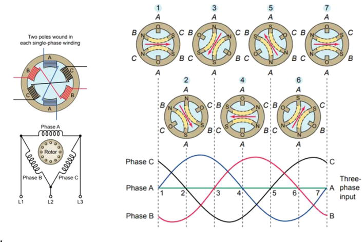
Figure 1.
Rotating magnetic field [
2. Using SimPowerSystems in control systems
One of the key advantages of using SimPowerSystems in the design and simulation of control systems for asynchronous motors is that it can help us to approach reality more closely than simple theoretical models [7, 8].
SimPowerSystems allows engineers and researchers to create virtual models of electrical power systems, including asynchronous motors and their associated control systems. These models can be used to simulate the behavior of the system under different operating conditions, such as varying loads and speeds [7, 8].
SimPowerSystems uses advanced mathematical models to represent the electrical, magnetic, and mechanical behavior of the system. These models take into account real-world phenomena such as magnetic saturation, rotor resistance, and voltage drops in the stator and rotor circuits. By using these detailed models, SimPowerSystems can provide a more accurate representation of the system’s behavior than simpler theoretical models.
SimPowerSystems also supports hardware-in-the-loop (HIL) simulation, which allows engineers to test their control systems using physical hardware, such as motor drives and controllers. This can help to further improve the accuracy of the simulation and identify any issues or limitations in the control system before implementing it in a real-world application [7, 8].
SimPowerSystems can help engineers to design and optimize control systems for asynchronous motors that are more accurate and realistic than simple theoretical models. This can help to improve the performance and reliability of the system while reducing costs and development time.
3. Asynchronous motor in Matlab simscape (SimPowerSystem)
To model an asynchronous motor using SimPowerSystems in SI units, a new Simulink model must be created. Once the model is created, engineers can then choose the appropriate asynchronous motor block from the SimPowerSystems library and set its parameters, such as the rated voltage, rated frequency, and the number of poles. The asynchrounous machine SI unites is shown in Figures 2 and 3.
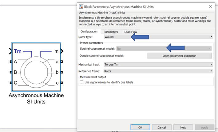
Figure 2.
Wound asynchronous motor.
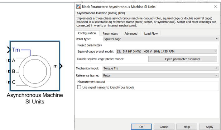
Figure 3.
Squirrel-cage asynchronous motor.
Change the wound asynchronous motor to squirrel-cage asynchronous motor and choose one motor from
3.1 Rated parameter three-phase asynchronous motor
When driving a three-phase asynchronous motor underrated (nominal) parameters, it is important to ensure that the motor is operated within its designed voltage, current, and frequency range. This includes [2, 3, 4, 5, 6]:
Voltage: The motor should be supplied with the nominal voltage specified by the manufacturer. Operating the motor at a voltage higher or lower than its nominal voltage can cause overheating, reduced efficiency, and premature failure.
Frequency: The motor should be operated at the nominal frequency specified by the manufacturer. Deviating from the nominal frequency can affect the motor’s speed and torque characteristics and can also cause overheating and premature failure.
Current: The motor should be operated within its rated current range. Overloading the motor can cause overheating and damage to the motor windings while operating the motor at low currents can result in reduced torque and efficiency.
Cooling: The motor should be adequately cooled to prevent overheating. This can be achieved through natural convection, forced-air cooling, or liquid cooling, depending on the motor’s design and operating conditions. In addition, it is important to ensure that the motor is properly installed, aligned, and coupled to the driven load. Regular maintenance and inspection can also help ensure that the motor continues to operate within its nominal parameters and provide reliable performance. Figure 4 represents the starting technic of the Squirrel-cage asynchronous motor.
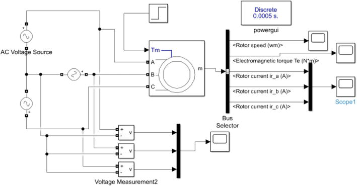
Figure 4.
Squirrel-cage asynchronous motor starting.
Ac voltage source 1: Peak amplitude:
Ac voltage source 2: Peak amplitude: 326.59 phase = −120 frequency = 50
Ac voltage source 3: Peak amplitude: 326.59 phase = 120 frequency = 50
Tm: rated torque: use step; step time: 1 initial value: 0 final value
As shown in Figure 5, select the bus selector to choose output of the machine.
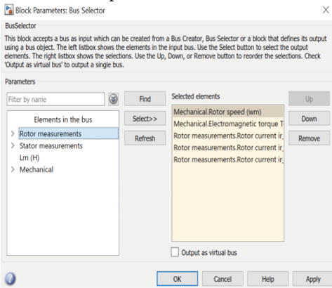
Figure 5.
Bus selector output.
3.2 Rated parameter three-phase asynchronous motor result
Run the simulation model, when the rated voltage is applied to the asynchronous motor, the motor begins to accelerate and increases its speed until it reaches its rated speed
As the load on the motor increases, the motor draws more current from the power supply to generate the required torque to overcome the resisting torque. This increased current causes a reduction in the motor’s speed, which will continue to decrease as the load on the motor increases (Figure 6).
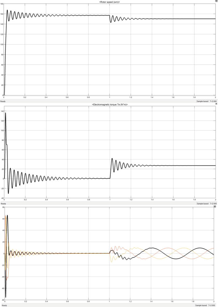
Figure 6.
Asynchronous motor output speed
4. Voltage control of the asynchronous motor
Voltage control of asynchronous motors using inverters is an effective technique for reducing starting current and improving the performance of the motor. However, it is important to consider the potential drawbacks and ensure that the system is properly designed and implemented to avoid any negative effects [8, 9].
Voltage control of asynchronous motors using inverters is a common technique used to reduce the starting current of the motor. In this method, the voltage supplied to the motor is controlled using an inverter to reduce the initial current surge that occurs during motor startup [10, 11, 12, 13, 14]. Figures 7 and 8 represent the voltage control of an Asynchronous motor in Matlab Simpower system environment.
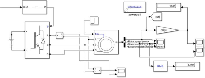
Figure 7.
Asynchronous motor, power part.
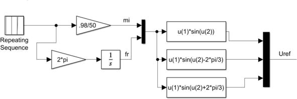
Figure 8.
Asynchronous motor voltage control, the control part.
The bloc repetitive sequence is responsible for the technique to reduce starting current; time value: [0 0.2 10], output value: [0 50 50],
Figure 9 shows that the motor speed responds quickly without a big overshot and for the starting current it does not exceed 25 A.
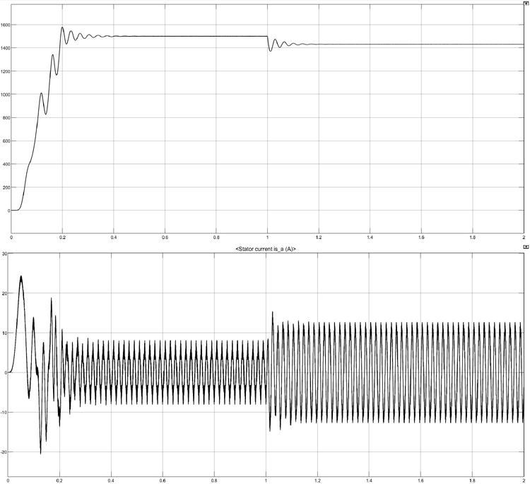
Figure 9.
Asynchronous motor output voltage control speed
5. Linear V/f speed control of the asynchronous motor
Linear
To overcome the limitations of linear
From the torque equation, if the slip is small enough, the torque slip curve in the stable region can be approximated by [9, 15, 16, 17]:
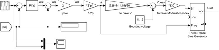
Figure 10.
Asynchronous motor linear
Figure 10 shows the linear
The output of the PI regulator represents the slip angular frequency
To calculate
PID controller P = 0.1 I = 1.82 (PID tuner method).
Figure 11 shows that the motor speed follows the reference speed perfectly, the motor responds quickly to the reference speed and reaches the speed of 100 rad/s in 2 s with a reduced overshoot of less than 30%, then when the reference speed changes to 120 rad/s the time response is equal to 0.2 s for the overshoot that is less than 3%, but if the reference speed changes to the other direction to −100 rad/s the time response and the overshoot increase to 2.5 s and 70%, respectively, a same note like before when the speed changes on the same direction to −50 rad/s the time response is equal to 0.2 s for the overshoot of less than 3%, and the time response and the overshoot increase to 2.5 s and 50%, respectively, if the speed changes the direction to 100 rad/s.
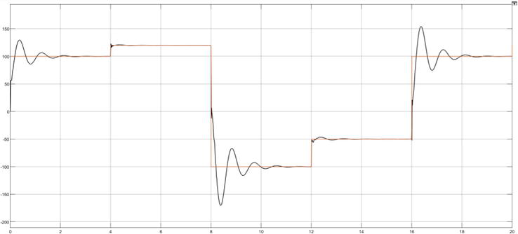
Figure 11.
Speed response asynchronous motor linear
6. Vector r V/f speed control of the asynchronous motor
Vector control, also known as field-oriented control (FOC), is a popular technique for controlling the speed and torque of asynchronous motors. Unlike V/F control, which controls the voltage and frequency applied to the motor, vector control directly controls the magnetic field and torque of the motor. This is achieved by decomposing the stator currents into two orthogonal components, known as the direct axis (Id) and quadrature axis (Iq) currents. The Id component represents the magnetizing current, while the Iq component represents the torque-producing current. By controlling the amplitude and phase of the Id and Iq currents, vector control can provide precise control of the motor’s speed and torque, even at low speeds and under varying loads. Vector control can also improve efficiency and reduce the noise and vibration of the motor. However, vector control requires more complex hardware and software compared to V/F control, it is typically more expensive to implement [9, 18, 19, 20, 21, 22, 23].
Vector control offers many benefits over other types of motor control, making it a popular choice for many applications requiring high-performance motor control; Advantages of vector control for asynchronous motors [9, 18, 19, 20, 21, 22, 23]:
High performance: Vector control allows for high-performance control of the asynchronous motor, resulting in better torque control and faster dynamic response.
Wide range of speed control: Vector control can control the speed of the motor across a wide range, making it suitable for use in a variety of applications.
Improved Efficiency: Vector control allows for the motor to operate at optimal efficiency by minimizing losses in the rotor and stator.
Reduced harmonics: Vector control reduces the harmonic content in the motor current, which results in less vibration, noise, and electromagnetic interference.
Sensorless control: Vector control can be implemented using sensorless techniques, which eliminates the need for additional sensors and reduces the overall cost and complexity of the motor control system [9, 18, 19, 20, 21, 22, 23].
Robustness: Vector control is robust to disturbances such as changes in load and supply voltage, making it suitable for use in harsh environments. Figure 12 represents the block diagram of vector control.
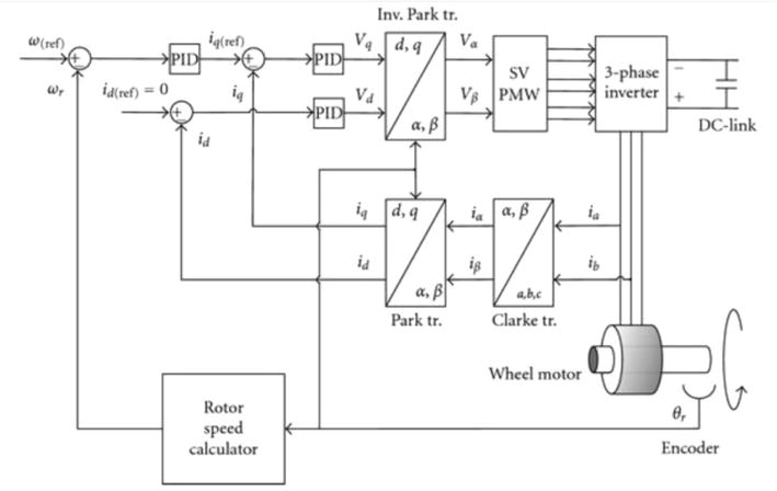
Figure 12.
Block diagram of vector control [
As shown in the Figures 13–15, FOC subsystem represents the bloc that resume the vector control of Asynchronous motor it has three inputs and one output; the inputs are the speed reference
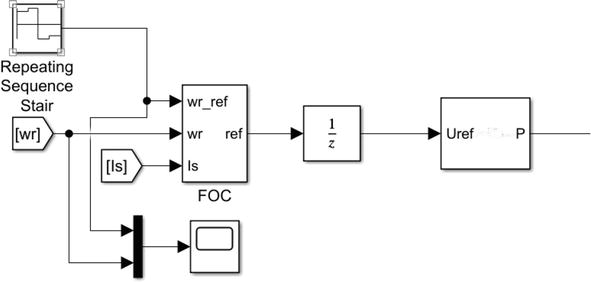
Figure 13.
Asynchronous motor FOC speed control, the control part.
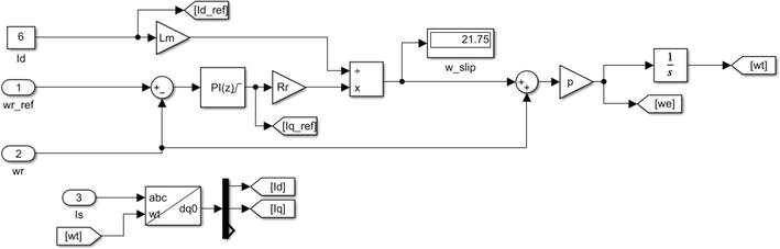
Figure 14.
Subsystem FOC speed control, part 1.
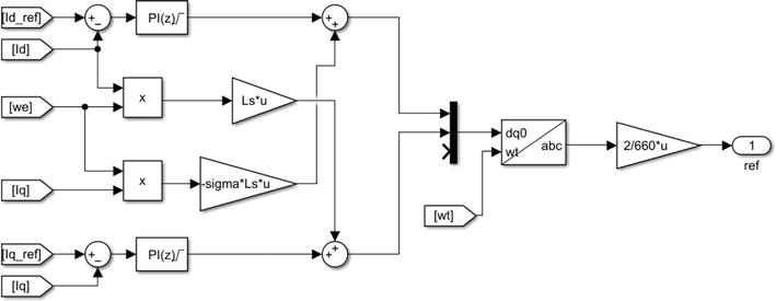
Figure 15.
Subsystem FOC speed control, part 2.
The outputs of the currents PI regulators ensure the first term of the equation then we add
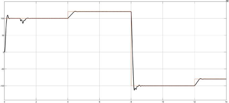
Figure 16.
Speed response asynchronous FOC speed control.
PI speed controller P = 0.6606563 I = 17.58084 (PID tuner method)
PI currents controller P = 14.39 I = 5800.047 (PID tuner method)
Figure 16 shows that the motor speed follows the reference speed perfectly; the motor responds quickly to the reference speed and reaches the speed of 100 rad/s in 0.4 s with a reduced overshoot of less than 9%, then when the reference speed changes to 120 rad/s the time response is equal to 0.4 s for the overshoot that is less than 0.75%, but if the reference speed changes to the other direction to −100 rad/s the time response and the overshoot increase to 0.7 s and 13%, respectively, after applying of a rated torque at 1 s a small disturbance is introduced on the response of the speed then the disturbance is rejected to return to the pursuit of the reference speed.
7. Conclusions
MATLAB SimPowerSystems was used to model and evaluate the performance of asynchronous motors under various control schemes. According to the simulation results, vector control is more efficient and offers superior dynamic performance than voltage control and V/F control. It is also important to note that the usage of SimPowerSystems in this study gives the simulation additional realism, which can then be immediately used in the construction of control systems utilizing hardware-in-the-loop simulation platforms such as dSPACE. This work offers important insights into how asynchronous motor performance changes with various control schemes, and it can be used as a useful resource for further study in this area.
Each of the three asynchronous motor control methods—voltage control, V/F control, and vector control—has specific benefits and drawbacks. Voltage control is straightforward and simple to use, but it has limitations when it comes to high performance and dynamic reactions. Although V/F control offers superior torque control and better dynamic response, it has problems with speed accuracy and stability. While improving torque response and speed stability, vector control provides the highest level of performance and control accuracy.
It should be emphasized that compared to the other two control systems, vector control is more expensive and challenging to execute because it requires more sophisticated hardware and software. Vector control has recently become more affordable and accessible because of technological improvements.
As a result, the selection of a control strategy for the operation of an asynchronous motor will be based on the particular needs of the application, taking into account elements such as complexity, cost, and performance. Overall, it is evident that vector control provides the best performance and control accuracy, making it the go-to choice for high-performance applications that demand exact torque and speed control. However, in less demanding applications where simplicity and cost-effectiveness are more crucial, voltage control and V/F control still have their place.
References
- 1.
You Electrical Guide. Three Phase Induction Motor - Working Principle. Your Electrical Guide. 2017. [Online]. Available: https://www.yourelectricalguide.com/2017/07/three-phase-induction-motor-working-principle.html - 2.
Fitzgerald AE, Kingsley Jr. C, Umans SD. Electric Machinery. New York: McGraw-Hill Encyclopedia of Science and Technology; 2003 - 3.
Wildi T. Electrical Machines, Drives, and Power Systems. New Jersey, U.S.: Prentice Hall; 2006 - 4.
Boldea I, Nasar SA. The Induction Machine Handbook. Boca Raton, Florida: CRC Press; 2010 - 5.
Miller TJE. Induction Motors. Boca Raton, Florida: CRC Press; 1993 - 6.
Patil HB, Mulay YS. Design and development of three-phase induction motor. International Journal of Engineering Research & Technology. 2015; 4 (6):1130-1135 - 7.
Zhang Y, Wang D. Modeling and simulation of AC motor drive systems using SimPowerSystems. IEEE Transactions on Industrial Electronics. 2017; 64 (7):5693-5703. DOI: 10.1109/TIE.2017.2661527 - 8.
Zhang Y, Wang D. Hardware-in-the-loop simulation of power electronics and electric machines using SimPower Systems. IEEE Transactions on Industrial Electronics. 2019; 66 (3):1983-1993. DOI: 10.1109/TIE.2018.2823105 - 9.
Novotny DW, Lipo TA. Induction motor vector control: A tutorial. In: Vector Control and Dynamics of AC Drives. Oxford University Press; 2008. pp. 171-219 - 10.
Ogata K. Modern control engineering. New Jersey, U.S.: Prentice-Hall; 1997 - 11.
Depenbrock M. Direct self-control (DSC) of inverter-fed induction machine. IEEE Transactions on Power Electronics. 1988; 3 (4):420-429. DOI: 10.1109/63.192770 - 12.
Rodriguez J, Pontt J, Correa P, Rebolledo R. Review of control strategies for improving dynamic performance of induction motors. IEEE Transactions on Industrial Electronics. 2007; 54 (6):2934-2945. DOI: 10.1109/TIE.2007.908302 - 13.
Ardebili M, Iravani R. Dynamic voltage restorer (DVR) compensation of voltage disturbances using synchronous-reference-frame control. IEEE Transactions on Power Delivery. 2004; 19 (1):405-413. DOI: 10.1109/TPWRD.2003.820838 - 14.
Bolognani S, Tani A. An innovative low-cost sensorless vector control for induction motor drives. IEEE Transactions on Industrial Electronics. 2010; 57 (8):2752-2762. DOI: 10.1109/TIE.2009.2037208 - 15.
Bose BK. Modern power electronics and AC drives. New Jersey, U.S.: Prentice Hall; 2002 - 16.
Krishnan R. Modeling and control of induction motor drives. Hoboken, NJ, United States: John Wiley & Sons; 2001 - 17.
Krishnan R. Electric Motor Drives: Modeling, Analysis, and Control. Vol. 32. Pearson Education India; 2010 - 18.
Leonhard W. Vector control of three-phase AC machines: System development in the practice. IEEE Industrial Electronics Magazine. 1996; 10 (2):26-33. DOI: 10.1109/57.491447 - 19.
Holtz J. Field-oriented control of AC machines. IEEE Transactions on Industrial Electronics. 2001; 48 (4):708-719. DOI: 10.1109/41.956193 - 20.
Novotny DW, Lipo TA. Vector control and dynamics of AC drives. England: Oxford University Press; 2008 - 21.
Botto MA. Advanced control of AC/DC power networks: System of systems approach based on spatio-temporal scales. In: In 2016 18th European Conference on Power Electronics and Applications (EPE'16 ECCE Europe). IEEE; 2016. pp. 1-10 - 22.
Noroozian R, Jafarzadeh M. Vector Control of Asynchronous Motor. London, UK, London, UK: INTECH; 2010. DOI: 10.5772/8673 Available from: https://www.intechopen.com/books/electric_motors_and_dr€ives/vector-control-of-asynchronous-motor - 23.
Oliveira JG, Schettino H, Gama V, Carvalho R, Bernhoff H. Implementation and control of an AC/DC/AC converter for double wound flywheel application. Advances in Power Electronics. 2012; 2012 :604703. DOI: 10.1155/2012/604703