 Open access peer-reviewed chapter
Abstract
Absorption refrigeration technology was introduced to address serious issues such as the energy crisis, rising fuel prices, and environmental concerns associated with traditional compression refrigeration systems. They are attracting increasing attention due to advantages such as the use of low-mass heat sources and environmentally friendly working materials. However, this technology has two major drawbacks, including the very large size of the refrigeration unit and a low coefficient of performance (COP), which hinder the commercial success of the absorption system. Considerable research has been done to develop strategies to improve the COP of absorption systems in order to make absorption refrigeration technology more competitive than conventional compression refrigeration systems. This chapter aims to provide a literature review on whether this technique is an effective and promising solution for augmentation.
Keywords
- absorption refrigeration
- coefficient of performance
- water/LiBr
- single-effect machines
- coefficient of performance (COP)
1. Introduction
Absorption cooling research has attracted the attention of many investigators in recent years as a result of the great growth of producing an environmentally friendly cooling system. The severity of the ozone depletion problem caused by CFCs and HCFCs has prompted the rapid development of CFC-free air conditioning technology. In terms of energy use, preventing global warming requires an overhaul of energy use practices to increase efficiency. From this point of view, absorption refrigeration research has attracted the attention of many researchers because it does not use ozone-depleting substances as refrigerants and can minimize the use of fossil fuel electricity. Vapor absorption cooling system uses heat rather than mechanical work as the energy input. The working fluid is the refrigerant while the material with which it is in solution is absorbent. The absorbent can be either in the liquid or the solid phase. The refrigerant is generally in the liquid or vapor phase, depending upon the process it is undergoing in the refrigeration cycle.
The most widely used absorption chiller is the ammonia-water machine, which uses ammonia (Li-Br) as the refrigerant and water (H2O) as the distribution (absorption) medium. Other absorption refrigeration structures consist of water-lithium bromide and water-lithium chloride structures, where water serves as the coolant. The latter systems are limited to air conditioning applications where the minimum temperature is above the freezing point of water.
The benefits of absorption systems have remained constant and include the following:
Absorption machines have lower electrical needs compared to vapor compression systems.
The input energy to absorption systems, is a low-grade form of energy (heat) and is readily available as waste in large power plants and factories. It is also available from alternative energy sources solar, biomass, geothermal, etc.
Absorption units pose no global environmental ozone depletion and may have less impact on global warming than most other options.
Absorption machines eliminate the concerns about lubricants in refrigerants.
Absorption units are economically attractive because fuel costs are substantially less than electric costs. Absorption equipment, which is heat driven, can both cool and heat for human comfort and process control. Heat sources for driving an absorption unit include the following:
Direct gas and oil firing
Indirect steam heating from boilers
Steam turbine exhaust
Gas turbine exhaust
Waste process steam
Cogeneration heat recovery steam or hot water
Hot processes fluids
Heat recovery from process steams and flue gases.
Of course, a small amount of mechanical work is added to the absorption system in the form of energy required to drive the solution recirculation pump. However, this is far less than the work required to run the compressor in the compression system, since the liquid has a smaller volume than the equivalent mass of vapor
With larger absorption units, water is usually cooled by passing it through the tubes of the evaporator. This cooled water then flows through air coils to air condition spaces fluid or through other exchangers to cool process fluids [1, 2].
2. Compression refrigeration cycles
The fully reversible Carnot cycle is an ideal model of a refrigeration cycle operating between two constant temperatures or between two fluids at different temperatures, each having infinite heat capacity. Reversible cycles have two important properties: first, no refrigeration cycle can have a higher coefficient of performance than a reversible Carnot cycle operating within the same temperature limits, and second, all reversible cycles operating within the same temperature limits have the same coefficient of performance (Figure 1)

Figure 1.
Carnot cycle on temperature-entropy coordinates. Source:
The heat is removed from the cooled area at a constant temperature
The output heat energy can be written as:
The input heat energy can be written as:
So, the network is equal to the difference between the heat energy output and input. And can be written as:
Therefore, the coefficient of performance can be written as [3]:-
3. Type of absorption refrigeration cycles
3.1 Single-effect machines
Most manufacturers offer single-effect machines in the range (of 100 RT to 1500 RT).
350 Kwth to 5.2 Mwth. These can be “fired” with steam at 135 to 205 kPa g (1–2 bar overpressure, 2–3 bar), corresponding to steam temperatures (110–120°C), or they can be “burned” with hot water (115–150°C). max. The pressure is 9 bar. With a coefficient of performance in the range (of 0.6–0.7), the steam consumption of a single-stage machine is about 2.3 kg/h/kwth. The required hot water flow is in the range (of 30–72 kg/h/kwth) depending on the allowable temperature drop [4].
3.2 Double-effect machines
Double-effect machines have roughly the same power range. Some manufacturers offer slightly higher minimum cooling capacities (200 RT for one company and 3500 RT for another) (700 and 1200 Kwth respectively). In the past, steam seemed to be the medium of choice for “igniting” such machines. The steam should be (8–10 bar), which corresponds to temperatures in the range of (175–185°C).
According to the information received, it is also possible to “fire” a double-effect Machine with hot water, the temperature of which should then be in the range (of 155–205°C).
The coefficient of performance, in either case, is (0.9–1.2).
The steam consumption of the double-effect machine is 1.2 kg/h per Kwth [4].
4. How absorption system works
Like the compressor in the electric vapor compression cycle, the absorption system uses its “hot” compressor (consisting of a generator, absorber, pump, and heat exchanger) to boil water vapor (refrigerant) in a lithium bromide/water solution and compresses the refrigerant vapor to a higher pressure. An increase in refrigerant pressure also increases its condensation temperature.
The refrigerant vapor condenses into a liquid at higher pressure and temperature. Since this condensation temperature is higher than the ambient temperature, heat will migrate from the condenser to the ambient air and be dissipated. The high-pressure fluid then flows through the throttle valve, reducing its pressure. Reducing its pressure also lowers its boiling point temperature. The low-pressure liquid then enters the evaporator and is cooked at a lower temperature and pressure.
Since the boiling temperature is now lower than that of the conditioned air, heat from the conditioned airflow enters the evaporator and boils this liquid. Removing heat from the air in this way causes the air to cool.
The refrigerant vapor then enters the absorber where it reverts to a liquid state It is drawn into the lithium bromide solution (absorption process).
The dilute lithium bromide solution is pumped back into the generator. Because lithium bromide (absorbent) Without boiling, the water (refrigerant) is easily separated by heating. The produced water vapor enters the condenser, the absorption solution returns to the absorber, and the process repeats.
Although the process is similar to a conventional electric vapor compression system, absorption refrigeration replaces an electric generator and an absorber called a thermal compressor, rather than an electric compressor. By using pumps instead of compressors and heat exchangers to recover heat and supply it to generators, efficiency can be increased and operating costs reduced. Double-effect absorption refrigeration adds a second generator and condenser to increase refrigerant flow and thus increase the cooling effect of a single-effect system for a fraction of the heat input [5] (Figure 2).
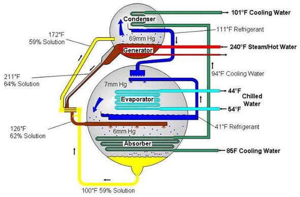
Figure 2.
Simplified diagram of a single effect absorption cycle. Source:
5. Basic thermodynamics of absorption cycle
Absorption cycles operate on the principle of refrigerant being absorbed by a chemical solution, normally water/LiBr or ammonia/water.
It is assumed that the reader is familiar with the basic absorption cycle. However, for clarity, a chiller schematic is shown in Figure 3 the top part of the unit is the driving cycle, where heat is supplied to the generator to boil off refrigerant that is condensed in the condenser. It also concentrates the solution (say water/LiBr) and supplies it via the solution heat exchanger to the cooling sub-cycle (evaporator and absorber), so enabling it to absorb more refrigerant. The main heat exchanges with the environment are:
High-temperature heat source: generator (i.e., steam, hot water, combustion).
Medium-temperature heat sink: absorber and condenser (cooling tower, condenser water).
Low-temperature heat source: evaporator (chilled water) [6].

Figure 3.
Single-stage absorption cycle on PTX diagram.
The cycle is represented on the pressure-temperature concentration (PTX) diagram in Figure 4 [7]. The horizontal axis indicates the solution temperature and the line inclined at 45° represents the pure refrigerant (water). From this line, the vertical saturation pressure axis values are determined. The constant concentration lines commence from the refrigerant line and indicate the percentage of LiBr. A very similar representation can be done in Figures 3 and 5 which uses different scales: in (P) and (−1/T). Two circuits (refrigerant and solution) can be identified on the PTX diagram: the left-hand side anti-clockwise quadrilateral (refrigerant circuit), and the right-hand side clockwise quadrilateral (solution circuit). It should be noted that each of the evaporation and condensation points indicates two phases: saturated liquid and vapor [8].

Figure 4.
Single-stage absorption chillers.

Figure 5.
Driving and cooling cycle.
6. Heat-driven cooling cycles
Absorption cycles can be associated with heat-driven cooling cycles, such as the case of a heat-driven power cycle that drives a mechanical compression refrigeration system described by Herold et al., as indicated in Figure 5.
Heat is supplied from a high-temperature heat source (generator or boiler) and from a low- temperature heat source (evaporator), and all this heat is released to a medium-temperature heat sink (absorber and condenser). The heat flows of a generalized absorption cycle are indicated in Figure 6.

Figure 6.
Heat flows of an absorption cycle.
Although absorption chillers require small pumps to circulate/re-circulate solution and refrigerant, for ideal cycles these can be considered negligible. By applying the first law of thermodynamics to the above:
If the second law of thermodynamics is applied, the total generation of entropy will be zero as we are analyzing an ideal cycle.
If the following assumptions are made, which are further explained later, and then the evaporator heat will be equal to the condenser heat
Saturated liquid-specific heat is negligible.
Heat of evaporation is constant.
Refrigerant expansion is isotropic.
Superheated vapor-specific heat is negligible.
By combining Eqs. (5) and (6) the absorber heat will be equal to the generator heat,
If the above (7) equations are combined, the following COP equation is derived in terms of the four temperatures involved, as shown in the following Eq. (9):
A way adopted by many authors has been to assume that the absorber and condenser share the same temperature. By doing this, the previous equation simplifies to the following:
This expression also indicates the COP as the product of the driving sub-cycle efficiency and the cooling sub-cycle COP if Carnot expressions are considered.
The two COP expressions derived above in terms of three and four temperatures are applicable to ideal heat-driven cooling cycles where the driving and cooling sub-cycles are independent of each other. This is the case for motor-driven compression systems and absorption GAX cycles. For single and multiple cycles there is no such independence between the driving and cooling sub-cycles, and further restrictions on temperatures are required and imposed [9].
7. Real absorption cycle on T-S diagram
Absorption cycles can be correctly represented on T-S diagrams, as they are best suited to represent ideal driving and cooling cycles (Carnot cycles). Due consideration should also be given to what is going to be represented on the T-S diagram. For this, it is necessary to split the refrigerant into two parts:
The part that circulates throughout the main processes (generator, condenser, evaporator, and absorber), which is what will be represented on the T-S diagram.
The other part, which is diluted in the solution and only circulates between the generator and absorber via the solution heat exchanger. It only experiences changes in temperature (and pressure) and is of minor thermodynamic importance if the solution heat exchanger area is sufficiently (infinitely) large. Therefore, this part of the refrigerant has no influence on the heat balance of the cycle, and will not be considered further [10].
To represent the absorption cycle on the T-S diagram, it will be made of the extended T-S diagrams developed by Eber.
A brief description of these extended diagrams will be given, but further details should be sought from the references.
A real absorption cycle (water/LiBr) is indicated in Figure 7 where the extended T-S diagram for that mixture has been used.

Figure 7.
Real absorption cycle on T-S diagram.
Due to their different vapor pressures, no equilibrium can exist between a pure refrigerant and the solution. Therefore, the refrigerant molecules in the solution are considered, and the solution is considered indirectly. The extended curves in the vapor region (right of the saturated vapor line, indicated 58% and 64%) consider the refrigerant vapor pressure to be in equilibrium with the solution. The extended curves in the liquid region (left of the saturated liquid line, indicated 58% and 64%) consider the states of liquid refrigerant in the solution. The horizontal difference between the extended liquid and vapor lines indicates the difference of entropy required to reversibly expel 1 kg of refrigerant from a very large quantity of solution, i.e. generator heat. From the previous figures, the refrigeration circuit.
Can be identified as:
1-2-3-4-5-6-7-8.
he processes in the refrigerant cycle are:
1-2: Heating and evaporation of the coolant introduced into the generator. Heat is equal to the sum of the heat of vaporization and heat of dissolution.
2-3: Cooling of the superheated steam generated in the constant pressure generator down to the saturation temperature Tc.
3-4: Condensation.
4-5: Isenthalpic expansion of the refrigerant from the condensation to the evaporation temperature.
5-6: clutch.
6-7: Isobaric (constant pressure) heating of the refrigerant in the form of saturated vapor or superheated vapor.
7-8: Absorption of superheated steam (state 7), in which the heat of solution and the heat of vaporization are released.
A minimum number of 12 idealizing assumptions are required to obtain an ideal absorption cycle. A summary of the assumptions follows:
Saturated liquid specific heat is negligible: The specific heat of the saturated liquid refrigerant along the lower boundary line is equal to zero. The implication of this is that the saturated liquid line is vertical on the T-S diagram.
Heat of evaporation is constant: The heat of evaporation is constant and independent of the temperature. This defines the saturated vapor line as a hyperbola on the T-S diagram.
Refrigerant expansion is isotropic: If this process changes from isenthalpic to isotropic, it becomes vertical on the T-S diagram (process 4-5).
Superheated vapor specific heat is negligible: The specific heat at a constant pressure of the superheated vapor is equal to zero. Therefore, the isobaric heating and cooling of vapor are represented as vertical lines on the T-S diagram.
Heat of solution varies only with concentration: The heat of solution/only depends on the composition of the solution and is not influenced by the temperature. Therefore, a family of hyperbolic curves will be derived for each solution concentration.
Solution-specific heat is negligible: Therefore, both the cooling and heating processes of the solution will be indicated by vertical lines on the T-S diagram.
Heat exchanger area is infinitely large: If the solution heat exchanger is sufficiently large, there is no sensible heating and cooling in the generator and absorber.
Solution circulation is infinitely high: Therefore, the concentrations of the strong and weak solutions converge.
Entropy of solution mixing is negligible with respect to the evaporation heat: This means that the mixing of solution will tend to be reversible.
Refrigerant vapor is an ideal gas: Which means that it complies with the properties of ideal gases.
There is no absorbent vapor pressure: Therefore, only the refrigerant will depart from the solution in the generator, and rectification is not necessary.
The solution pump work is considered to be negligible [11].
8. Working pairs in absorption refrigeration units
The working fluid pairs to be used in absorption refrigeration units must be selected on the bases of their suitability under the conditions of Their thermodynamic properties, chemical and thermal stability, and toxicity. Examples of working substance pairings and applications that have been extensively developed are:
Ammonia water is used in air conditioning and refrigeration. Ammonia is a refrigerant and water is a solvent. The performance values of the process depend on the temperature, which reaches a level of (−45°C). The main field of application of ammonia is large-scale use in the MW range.
The ammonia-hydrogen combination has been used in domestic refrigerators.
Aqua-LiBr solution has been used in domestic and commercial air conditioners, which can reach power values of 0.65 (single stage) and 1.10 (two stages), the required heating temperature is 90–115° C, and the small volume reaches the temperature level (6° C).
Usually, one of two types of absorption chillers are used, mainly depending on the required cooling temperature:
For the cooling temperature above 5°C, a water/lithium bromide absorber is the most commonly used and must be water-cooled.
The ammonia water machine can be used when the cooling temperature is lower than 5°C. It can be air-cooled or water-cooled.
A pair of thermodynamic properties used in absorption refrigeration plants are:
The latent heat of vaporization of the refrigerant is high,
Refrigerant vapor pressure is low but above atmospheric pressure,
Thermal mixing or low or negative reaction,
The intrinsic heat capacity of the absorbing solution is low compared to the latent heat of the refrigerant,
no crystallization or freezing within the range of operating conditions, and.
High solubility of the refrigerant in the absorber [11].
9. Conclusion
If the vapor leaving the evaporator is accompanied by some liquid, this is not a major disadvantage in the operation of absorption chillers, but it can be a risk in compression chillers. To prevent this (the vapor escaping with the liquid) in compression refrigeration systems, the compressor must have special controls. This issue can be very important in applications with widely varying cooling requirements.
Large-capacity absorption chillers take up more space than compression chillers. However, the units can also be placed outside the building and can be made taller rather than wider and deeper, taking up less floor space.
With the development of urban natural gas absorption chillers, the consumption of natural gas has increased year by year, resulting in air pollution, especially in summer.
Some industries generate unwanted heat through various processes, which is wasted by being transferred to the surrounding air. However, these industries actually need to cool down. Using waste heat in an absorption chiller to generate the required cooling is a viable solution and, in this case, establishes a viable symbiosis.
Absorption chillers have a very low COP, using about four times as much energy (in the form of heat) to produce a given amount of cooling.
The cooling of the condenser and absorber in absorption chillers uses about twice as much water as the condenser in compression chillers (if these systems are water-cooled). Absorption chillers are not widely used due to the scarcity of water and the need to conserve water as its value increases every day.
References
- 1.
Nikbakhti R, Wang X, Hussein AK, Iranmanesh A. Absorption cooling systems–Review of various techniques for energy performance enhancement. Alexandria Engineering Journal. 2020; 59 (2):707-738 - 2.
Wang S. Handbook of Air Conditioning and Refrigeration. New York: McGraw-Hill; 1984 - 3.
ASHRAE Handbook of Fundamentals. Atlanta: American Society of Heating, Refrigeration and Air-Conditioning Engineers; 2005 - 4.
Felli M. Absorption Refrigeration Thermodynamics. Parl 1A ASHRAE Transactions. 1999; 89 (2748):189-204 - 5.
Alefeld G. Double Effect, Triple Effect and Quadruple Effect Absorption Machines. 16th Int. Vol. 2 Paris: Congress of Refrigeration; 1999. pp. 951-956 - 6.
ASHRAE Handbook of HVAC Applications. Atlanta: American Society of Heating, Refrigeration and Air-Conditioning Engineers; 2004 - 7.
Lahoud C, Al Asmar J, Brouche M. Review of cogeneration and trigeneration systems. African Journal of Engineering Research. 2018; 6 (3):39-54 - 8.
An Introduction to Air Conditioning Systems. Harwell UK: Good Practice Guide No 256, Energy Efficiency Best Practice Program, ETSU; 1999 - 9.
Eber N. A New Analysis of Rectification in Absorption Refrigeration. Madrid: paper 3.14, Proceedings of the XII International Congress of Refrigeration; 1967. pp. 1339-1351 - 10.
Herrmann F. The absorption refrigerator as a thermal transformer. European Journal of Physics. 2009; 30 (2):331 - 11.
Tozer, James R. Thermodynamics of Absorption Refrigeration (Ideal Cycles), Paper E5, International Absorption Heat Pump Conference. Louisiana, USA: ASME pub.; 1994. pp. 393-400