Open Access is an initiative that aims to make scientific research freely available to all. To date our community has made over 100 million downloads. It’s based on principles of collaboration, unobstructed discovery, and, most importantly, scientific progression. As PhD students, we found it difficult to access the research we needed, so we decided to create a new Open Access publisher that levels the playing field for scientists across the world. How? By making research easy to access, and puts the academic needs of the researchers before the business interests of publishers.
We are a community of more than 103,000 authors and editors from 3,291 institutions spanning 160 countries, including Nobel Prize winners and some of the world’s most-cited researchers. Publishing on IntechOpen allows authors to earn citations and find new collaborators, meaning more people see your work not only from your own field of study, but from other related fields too.
To purchase hard copies of this book, please contact the representative in India:
CBS Publishers & Distributors Pvt. Ltd.
www.cbspd.com
|
customercare@cbspd.com
A fire can happen anytime and anywhere. That is why the fire resistance of our structures is important. Adequate fire resistance enables the evacuation of people and material goods, fire-fighting intervention, but also the possibility of reusing the building after the fire with minor or major retrofitting works. Our structures are made of different construction materials, and these materials behave differently in fire conditions, while we build our structures to last 50, 100, or 200 years. That is why the selection of structural and other construction materials is extremely important. Concrete is not combustible, does not transmit flame, does not release toxic gases in a fire and is not a fire load. However, fire has a negative impact on concrete structures as well, especially since concrete is a composite material, so there is a reduction in the mechanical properties of both concrete and the embedded steel. The most sensitive reinforced concrete elements in a fire situation are thin-walled elements such as RC slabs, which have a thin concrete cover. In this research, using four world famous methods, we try to figure out the factors influencing the fire resistance of RC slabs as the most sensitive reinforced concrete elements to fire.
Faculty of Technical Sciences, Department of Civil Engineering, University of Bihac, Bihac, Bosnia and Herzegovina
*Address all correspondence to: ninsa_d@hotmail.com
1. Introduction
Despite modern firefighting methods and new technologies, fires still pose a great danger to both population and property. A fire is an uncontrolled burning of fuel that spreads uncontrollably in time and space and poses a danger to human life and material goods. We protect structures from fire using active and passive fire protection measures. One of the passive measures to protect structures from fire is the correct selection of both structural and other materials from which we build the structures and which we install into the building itself. Statistics in the developed countries of the world in the past 50 years show that the number of fires on structures is continuously decreasing, as well as the number of injured and dead people in those fires. This positive trend was significantly contributed by the increase in awareness of the dangers of fire, the development of science and technology in the field of fire protection, and the development and application of active and passive fire protection measures, but also the development of research focusing on the behavior of materials and structures in fire conditions, which resulted adopting modern standards. However, fire still remains a danger to people, property, and the economy.
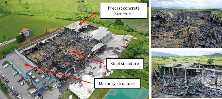
In this regard, reaction to fire of different materials and fire resistance of different structures are of the most significant interest and consideration nowadays. The behavior of structures in fire conditions depending on the structural materials they are made of, size, shape and dimensions of the building, ventilation conditions, as well as thermal characteristics of the material applied at boundary surfaces of the observed building including applied fire protection active and passive measures, as well as type and density of fire load is significantly different. Figure 1 shows the aftermath of one fire of the factory that was constructed in sections with masonry, steel, and concrete structures.
Figure 1.
Fire aftermath and structures made of different materials.
In addition, EU Regulation No. 305/2011 specifies “that construction works as a whole and in their separate parts must be fit for their intended use, taking into account in particular the health and safety of persons involved throughout the life cycle of the works” [1]. The same document sets up seven requirements that structures should fulfill, while the second one is related to safety in fire, immediately after the first one related to mechanical resistance and stability.
The same document also provides the following essential requirement for the limitation of fire risks: “The construction works must be designed and build in such a way, that in the event of an outbreak of fire, the load-bearing resistance of the construction can be assumed for a specified period of time, the generation and spread of fire and smoke within the works are limited, the spread of fire to neighboring construction works is limited, the occupants can leave the works or can be rescued by other means and the safety of rescue teams is taken into consideration” [1].
Among other reasons, this research is inline as a contribution to the aforementioned criteria, especially when it comes to concrete structures and reinforced concrete slabs as probably the most vulnerable concrete elements in fire conditions, wishing to contribute to a certain extent to both design and construction practice, but also in assessment of the existing structures that have experienced a fire and guidelines for possible retrofit of the such structures.
Qualitative comparative research methodology was used in this research. It aimed to determine fire resistance of the RC slabs using four methods. In the first stage, the available methods and their principles for determining fire resistance of concrete elements including main aspects of standard fires, properties of concrete and reinforcing steel at elevated temperatures, and fire resistance were discussed.
After that, empirical analysis of fire resistance of RC slabs of different spans, depth, concrete class, type of aggregate used, steel reinforcement, variation of concrete cover, and actions was done. This research was conducted to determine factors of influence that govern fire resistance of RC slabs.
There are three considered research questions in this study. The first one is related to the general fire resistance of RC slabs designed for ambient temperatures. The second is related to contribution of concrete class to the fire resistance of RC slabs, while the third research question focuses on the contribution of the thickness of concrete cover to fire resistance of RC slabs. The findings on these research questions will inform on the research hypothesis that proper selection of the concrete class and cover can significantly affect the fire resistance of RC slabs.
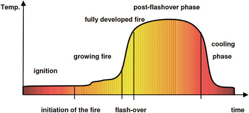
The most fires can be modeled through the curve of temperature and time dependence. How does a fire develop? At the very beginning, a fire in a room has the characteristics of an outdoor fire with a relatively low temperature and a limited range with a gradual increase in temperature. At this stage, the active fire protection measures are the most effective. If the active fire protection measures are not effective at this stage of fire development, the temperature in the room increases due to the preheating of the combustible material in the room, and the temperature rises to several hundred degrees. When the temperature reaches about 600°C in the higher zones of the room—ceiling, a complete flare-up of the fire occurs, which is in the literature called flashover (Figure 2).
Figure 2.
Real fire model [2].
This phenomenon looks spectacular, and the fire passes into the stage of a fully developed fire, when the action of active fire protection measures is limited, and fire very quickly reaches the maximum temperature.
It is important to note that every real fire has an ascending and descending branch of fire development in the room. When the temperature in the room drops to 80% of the maximum developed temperature during the fire, it is considered that the burn-out phase has begun because the available amount of fuel that can release heat decreases, given that it has already been consumed in the previous phases of the fire.
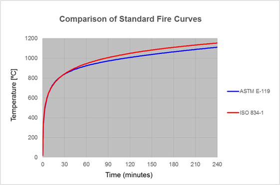
Considering that every real fire develops in its own style, depending on many factors (e.g., shape, dimensions, room size, quantity, and type of fire load, and many other factors), it was necessary to define a standard fire to evaluate the fire resistance of structures, elements, and building products in fire conditions applying standardized procedures. The standard fire defined by The International Standard ISO 834-1—Fire Resistance Tests—Element of Building Construction from 1999 [3] is widely accepted for this purpose in most countries in the world. Eurocode 1 (EN 1991-1-2: 2002) [4] also adopts this temperature–time curve as a nominal curve. This standard fire curve is defined as:
T=345log108t+1+20E1
where.
T – average temperature in the test furnace in °C;
t – test time in minutes.
This standard fire curve is applied as action to structures for the determination of fire resistance of RC slabs for methods used for determining fire resistance of RC slabs in this research, namely EN 1992-1-2:2004, Eurocode 2, Design of concrete structures, Part 1–2: Structural fire design [5] and BRANZ Technical Recommendation No. 8 – Method for Fire Engineering Design of Structural Concrete Beams and Floor Systems [6].
The standard fire curve is used in the USA and along the ACI/TMS 216.1—Code Requirements for Determining Fire Resistance of Concrete and Masonry Construction Assemblies [7] is the standard fire curve temperature-time ASTM E 119 [8], and in this research it is presented with a number of discrete points as shown in Table 1.
Time (t) (min)
Temperature of standard fire ASTM E 119 (°C)
5
538
10
704
30
843
60
927
120
1010
240
1093
480 and over
1260
Table 1.
Temperature dependance for standard fire ASTM E 119 [8].
Lie [9] gave several equations that mathematically approximate the ASTM E 119 curve, where the simplest one gives the temperature in function of time through the following relationship:
T=7501−e−3.79553th+170.41th+T0E2
where
th – test time expressed in hours.
These two standard fire curves are rather similar but not the same, and a comparison is presented in Figure 3.
4. Methods for fire resistance determination of RC slabs
In order to approach the determination of the fire resistance of reinforced concrete slabs, the following considerations provide the basic principles of the available methods that are used in this research.
4.1 Eurocode 2: design of concrete structures, part 1-2: structural fire design
All Eurocodes relating to structural materials have a part 1–2 which deals with structural fire design, while Eurocode 1 has a part 1–2 related to actions on structures exposed to fire. Related to the EN 1992-1-2:2004, Eurocode 2, Design of concrete structures, part 1–2 [5], it deals with structural fire design of concrete structures. This European Standard defines three groups of methods for determining the fire resistance of concrete structures: tabular method, simplified calculation methods, and advanced calculation methods.
When determining the fire resistance of concrete structures or elements, nominal fire curves and parametric curves defined in Eurocode 1 can be used as a fire action to structure or element. The following three criteria are supposed to be considered in determining the fire resistance of concrete structures or elements:
Mechanical resistance, load-bearing function (Criterion R);
Integrity, separating function (Criterion E); and
Insulation (Criterion I).
In accordance with EN 1992-1-2:2004—Structural Fire Design [5], Criterion “R” is considered fulfilled when the structure or its element retains its load-bearing function including meeting the stability conditions for the required fire exposure time. Integrity Criterion “E” represents the ability of the separating element to prevent the occurrence of fire and gases on the fire non-exposed side of the element, when exposed to standard fire on its other side and for the required period of time. The separating element meets the requirements of Insulation Criterion “I” if the average temperature rise on the side not exposed to fire does not exceed 140 K, and the maximal temperature rise at any point of the separating element does not exceed 180 K, when exposed to a standard fire on the other side, and during the required period of time.
Different elements should meet different criteria depending on their function in the building. Thus, a reinforced concrete slab or load-bearing reinforced concrete wall should meet all three criteria, while a reinforced concrete beam or column should only meet Criterion “R”, and a non-load-bearing partition wall should meet criteria “E” and “I”. [11].
Along the fire resistance analysis of the structural element, the reduction factor ηfi for actions in fire situation is applied in relation to the design at normal (ambient) temperature:
Ed,fi=ηfi∙EdE3
where
Ed,fi—design effect of actions in the fire situation;
Ed—design effect of actions for the ambient temperature design;
ηfi—reduction factor for the design load level for the fire situation.
The values of partial safety factors in structural fire design for thermal and mechanical properties of materials (concrete and reinforcement) are γM, fi = 1.0.
4.1.1 Tabulated data
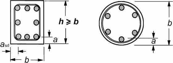
The tabulated data provide relatively simple and easy-applied solutions for everyday engineering practice and based on the “axial distance” of the reinforcement from the nearest fire-exposed surface of the concrete element when exposed to a standard fire up to 240 min for different types and functions of concrete elements. The data are given for concrete of normal weight (2000–2600 kg/m3) made of quartz aggregate and can be also used for concrete made of calcareous aggregate applying a reduction of minimum dimensions of 10%. The axial distance “a” is defined as the distance from the centroid of the reinforcement to the nearest fire-exposed surface of the concrete element according to Figure 4.
Figure 4.
Axis distance [5].
The origin of data displayed in the tables for the minimum dimensions and axial distances of concrete elements to meet the Criterion “R” that comes from the following equation:
Ed,fiRd,fi≤1.0E4
where
Ed,fi—design effect of actions in the fire situation; and.
Rd,fi—design load-bearing capacity in the fire situation.
Axis distance given in Table 2, Column 3, for one-way simply supported slabs are based on critical temperature of the steel reinforcement Өcr = 500°C and the reduction factor for design load level in the fire situation ηfi = 0.7, which corresponds to Ed,fi = 0.7 Ed, where Ed is designed effect of action at normal (ambient) temperature according to EN 1992-1-1 and partial safety factor for steel γs = 1,15 at ambient temperature. For satisfying the Criteria E and I, the minimal depth of slab is also prescribed in Table 2, Column 2.
Minimum dimensions and axis distance for simply supported concrete slabs [5].
Normally, the cover required by EN 1992-1-1 will control.
lx and ly are the spans of a two-way slab (two directions at right angles) where ly is the longer span.
For prestressed slabs, the increase of axis distance according to 5.2(5) should be noted.
The axis distance a in Column 4 and 5 for two-way slabs related to slabs supported at all four edges. Otherwise, they should be treated as one-way spanning slab.
4.1.2 Simplified calculation method for beams and slabs
The Eurocode 2, part 1–2, Annex E [5] provides a simplified calculation procedure for a more precise determination of the fire resistance of concrete beams and slabs when the actual axial distance of the centroid of the reinforcement from the nearest surface exposed to fire has a smaller value than prescribed in the tabular method, or a more precise extension of tabular method. It refers to beams and slabs designed by methods of linear analysis or linear analysis with a limited distribution at ambient temperature, and which are loaded predominantly with uniformly distributed load along the length of the beam or slab surface.
The main guideline of this procedure is to ensure that the design bending moment in fire conditions is less than or equal to the cross-sectional moment capacity in the fire situation:
MEd,fi≤MRd.fiE5
For the simply supported slab, the cross-sectional moment capacity in the fire situation is determined according to the following relationship:
MRd,fi=γsγs,fi∙ksθ∙MEd∙As,provAs,reqE6
where.
γs—the partial safety factor for steel used for ambient temperature.
γs,fi—the partial safety factor for steel in fire conditions;
ks (θ)—steel strength reduction factor for the given temperature θ for the required time of fire resistance;
MEd—designed bending moment for ambient temperature design;
As,prov—actual cross-sectional area of tensile steel reinforcement provided; and.
As,req—design required cross-sectional area of tensile steel reinforcement at the ambient temperature according to EN 1992-1-1 [12].
It is important to note that ratio of actual cross-sectional area of tensile steel reinforcement provided As, prov, and design required cross-sectional area of tensile steel reinforcement at the ambient temperature As, prov should not be greater than 1.3.
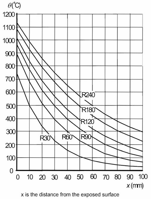
Temperature of concrete in fire situation θ can be determined based on temperature profiles for slabs given in EN 1992-1-2: 2004 Annex A, [5], as shown in Figure 5.
Figure 5.
Temperature profiles for slabs (depth 200 mm) [5].
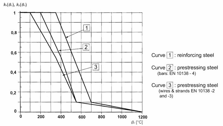
In determination of fire resistance of concrete elements, it is common to assume that temperature of concrete and temperature in the reinforcement are the same at the same fiber of concrete element in fire conditions. Using this assumption, the steel strength reduction factor ks(θ) at the temperature θ for the required fire resistance period can be determined from the next diagram (Figure 6).
Figure 6.
Steel strength reduction factors [5].
4.2 BRANZ technical recommendation No. 8: method for fire engineering design of structural concrete beams and floor systems
Based on the results of a large number of tests on the fire resistance of concrete elements, which were sponsored by the Portland Cement Association in the USA, a procedure for determining the fire resistance of reinforced concrete and prestressed beams and slabs was developed by BRANZ – The Building Research Association of New Zealand and was published as BRANZ Technical Recommendation No. 8 [6]. The specific of this method is that represents a combination of principles for determining fire resistance according to ACI 216.1–97/TMS 0216.1–97, but in this procedure the action on the structure can also be modeled according to standard fire ISO 834-1.
Among other specifics, the method is applicable for determining the fire resistance of the simply supported or continious concrete slabs with or without restraints against termal expansion, made of normal weight or lightweight concrete as reinforced or prestressed. It is possible to determine the resistance to fire from 60 to 240 minutes.
The simply supported reinforced concrete slabs without restraints against thermal expansion and made of concrete of normal weight are focus of this research, so the aspects of this method related exclusively to the stated subject of research are presented in the further considerations.
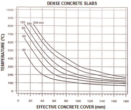
The procedure begins by determining the effective concrete cover Ce as the shortest distance between the centroid of the individual steel bars and the fire-exposed surface of the slab.
Based on a series of fire resistance tests in the USA by the Portland Cement Association, the diagram in Figure 7 was developed, which is used to determine the nominal temperature of the steel reinforcement for the required period of fire resistance as a function of effective concrete cover.
Figure 7.
Reinforcing steel temperature determination [6].
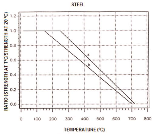
Once the nominal temperature of the tensile steel reinforcement Ts is determined, it is possible to determine its yield strength at elevated temperature using equation (Eq. (7)), or via the diagram displayed in Figure 8 using the bilinear diagram “a” for the concrete reinforcing steel. The bilinear diagram “b” is used for prestressing steel:
Figure 8.
Ratio of steel yield strength at elevated temperatures [6].
fyTfy20°C=fx=1.0forT≤250°C1.53–T470forT>250°CE7
where
T —temperature of steel in °C;
fy (20°C)—characteristic yield strength of reinforcing steel at normal-ambient temperature;
fy (T)—yield strength of reinforcing steel at temperature T in °C.
In order to satisfy the equilibrium conditions in cross section of the slab, it is necessary to know the dimensions of the effective compression block of concrete and the compressive strength of concrete in fire conditions. According to this method, the effective compression concrete in fire conditions is considered when concrete temperature does not exceed 750°C. However, considering that the concrete compression block of simply supported concrete slab is not directly exposed to fire, the width of the compression concrete blok is equal to 1.0 m, and in most of these cases the temperature of the compression concrete block is below 350°C. Then the depth of the compressiion concrete block (aӨ) can be determined according to the following formula:
aθ=As∙fyθ0.85∙fcθ′∙bθE8
where
aθ—depth of the equivalent rectangular compression stress block at the required time of the fire resistance;
As—cross-sectional area of tensile reinforcing steel provided;
fyθ—yield stress of reinforcement at the temperature θ;
f’cθ—reduced compressive strength of concrete at the temperature θ;
bθ—reduced width of concrete compression block at the temperature θ (equal 1.0 m for slabs).
For the determination of compressive strength of normal-weight concrete at elevated temperatures, the following equation is used:
f ‘c (20°C)—characteristic compression strength of concrete at the normal-ambient temperature;
f ‘c (T)—compression strength of concrete at the temperature T.
As noted earlier, in most cases, the temperature of concrete in compression is below 350°C, so the compression strength of concrete in a fire situation is equal to the compression strength of concrete at normal-ambient temperature. This fact simplifies the procedure for concrete slabs.
Then, the bending moment capacity of the slab Mθ+ in fire situation is as follows:
Mθ+=As∙fyθ∙dθ−aθ2E10
where
dθ—effective depth of the slab in fire situation.
The safety factor for permanent actions in fire situation is 1.0 according to this Technical Recommendation, while the safety factor for the variable actions depends on the type of structure. For domestic, office, parking, and trafficable roofs, the safety factor for variable actions is 0.4, for floors in storages and other structures is 0.6, while it is 0 for non-trafficable roofs. The slab has the required fire resistance if the bending moment capacity is greater than the maximum applied bending moment in a fire situation.
4.3 ACI/TMS 216.1—code requirements for determining fire resistance of concrete and masonry construction
Based on research conducted by Martin, Gustaffero, Bletzacker, Harmathy, Abrams, and others, ACI/TMS Committee 216 developed a standard method for determining fire resistance of concrete and masonry structures presented in ACI/TMS 216.1 [7].
This method enables the design of fire-resistant concrete structures as well as the assessment of the fire resistance of existing concrete structures when exposed to standard fire ASTM E-119. The combination of actions in fire situation used in this method is prescribed in Appendix C2.5 from ASCE 07, Minimum Design Loads for Buildings and other Structures [8] for the calculation of moment due to full-service load on member M.
On the basis of structural end-point behavior, the fire resistance of a simply supported, unrestrained slab is as follows:
Mn≥Mnθ≥ME11
where
Mn—the nominal moment capacity at section;
Mnθ—the nominal moment capacity of section at elevated temperature;
M—the moment due to full-service load on a member.
If the reinforcement is straight and equal along the entire span of the slab, then the nominal moment capacity at section is also equal along the entire span of the slab, and it is as follows:
Mn=As∙fy∙d−a2E12
where
As—cross-sectional area of longitudinal tension reinforcement;
fy—specified yield strength of reinforcing steel;
d—effective depth, distance from centroid of tension reinforcement to extreme compressive fiber;
a—depth of equivalent rectangular concrete compressive stress block at nominal flexural strength.
a=As∙fy∙0.85∙fc′∙bE13
where
fc′—specified compressive strength of concrete;
b—1.0 m for slabs (width of compression zone).
It is generally assumed that dead and live loads remain constant during the fire. However, the strength of materials is reduced so that the nominal moment capacity of section at elevated temperature is
Mnθ=As∙fyθ∙d−aθ2E14
in which Ө signifies effects of elevated temperatures. Note that cross-sectional area of longitudinal tension reinforcement As and effective depth d are not affected but yield strength of reinforcing steel fyθ is reduced. Similarly, depth of equivalent rectangular concrete compressive stress block aθ is reduced, but the compressive strength of concrete strength at the top of the slab fc′ is generally not significantly reduced. In addition, the period of fire resistance of the observed slab depends on the time required to reach the critical temperature of the steel, which again depends on the applied concrete cover.
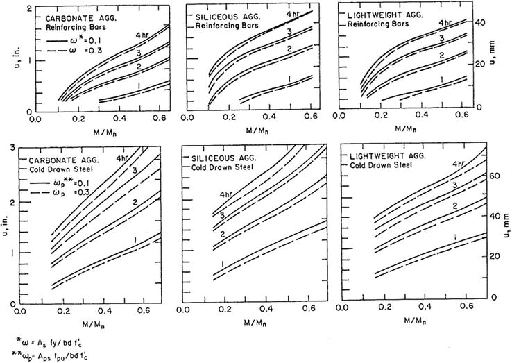
Depending on the type of aggregate from which the concrete is made, the type of reinforcement, the ratio of moment due to full-service load and the nominal moment capacity M/Mn, and the average thickness of concrete between the center of main reinforcing steel and fire-exposed surface u, calculating the reinforcement index for concrete slab as:
ω=As∙fyb∙d∙fc′E15
it is possible to determine fire resistance of slab using diagrams given in Figure 9.
Figure 9.
Fire resistance of concrete slabs as influenced by aggregate type, reinforcing steel type, moment intensity, and “u” [7].
In this research, we consider the fire resistance of simply supported reinforced concrete slabs, spans of 3, 5, and 7 m, and slab thicknesses of 12, 15, and 17 cm, respectively. For each span and slab height, the concrete classes C20/25, C 30/37, and C 40/50 are varied, wishing to establish the influence of different concrete classes on the fire resistance of RC slabs. The thickness of the concrete cover also varies from 0.5 to 3.0 cm, in increments of 0.5 cm. The use of thicker concrete covers in reinforced concrete slabs is not rational, so they are not used in this research. We are aware that EN 1991-1-1: 2004 does not allow the use of concrete cover of 0.5 and 1.0 cm, but the reason for the analysis of these concrete cover thicknesses enables to more precisely establish the dependence and contribution of concrete cover to the fire protection of reinforcement and reaching its critical temperature, while with on the other hand, it is neither impossible nor a rare, that during the execution of works, the thickness of the concrete cover is realistically smaller than designed in the actual construction. All slabs are reinforced with welded reinforcing mesh of steel grade B500A, Ductility Class A, Yield = Re 500 MPa or individual rebar of steel grades B500A or St-500-b.
The slabs are previously designed according to EN 1991-1-1: 2004 at ambient-normal temperature. Thereby, the self-weight of the slab and the layers of the floor structure of 1.5 kN/m2 are assumed as permanent actions, while variable load of 2 kN/m2 was taken in design. For all variations of concrete slabs, fire resistance was determined according to all four methods described in this research. The fire was modeled using standard fire according to ISO 834-1 for the first three methods, while standard fire ASTM E 119 was used for the fourth method. The results of this research are shown in Tables 3–11.
Fire resistance of slab Depth 12 cm, span 3 m, C 20/25, qd = 9.075 kN/m2
Concrete cover (cm)
as (cm)
MEd, fi (kNm/m’)
Reinforcement
Bar diameter (mm)
EN 1992-1-2 simplified method for slabs
EN 1992-1-2 tabulated data
BRANZ TR 8
ACI/TMS 216.1
0.5
0.825
7.14
R 221
6.5
R ∅
R ∅
0 min
<60 min
1.0
1.275
R 238
5.5
R 30
R 30
30 min
<60 min
1.5
1.850
R 257
7.0
R 30
R 30
30 min
<60 min
2.0
2.350
R 257
7.0
R 60
R 60
60 min
<60 min
2.5
2.800
R 283
6.0
R 60
R 60
60 min
60 min
3.0
3.325
R 335
6.5
R 90
R 90
90 min
60 min
Table 3.
Fire resistance of RC slab, span 3 m, depth 12 cm, C 20/25.
Fire resistance of slab Depth 12 cm, span 3 m, C 30/37, qd = 9.075 kN/m2
Concrete cover (cm)
as (cm)
MEd, fi (kNm/m’)
Reinforcement
Bar diameter (mm)
EN 1992-1-2 simplified method for slabs
EN 1992-1-2 tabulated data
BRANZ TR 8
ACI/TMS 216.1
0.5
0.825
7.14
R 221
6.5
R ∅
R ∅
0 min
< 60 min
1.0
1.300
R 238
5.5
R 30
R 30
30 min
< 60 min
1.5
1.850
R 257
7.0
R 30
R 30
30 min
< 60 min
2.0
2.350
R 257
7.0
R 60
R 60
60 min
< 60 min
2.5
2.800
R 283
6.0
R 60
R 60
60 min
60 min
3.0
3.325
R 335
6.5
R 90
R 90
90 min
60 min
Table 4.
Fire resistance of RC slab, span 3 m, depth 12 cm, C 30/37.
Fire resistance of slab Depth 12 cm, span 3 m, C 40/50, qd = 9.075 kN/m2
Concrete cover (cm)
as (cm)
MEd, fi (kNm/m’)
Reinforcement
Bar diameter (mm)
EN 1992-1-2 simplified method for slabs
EN 1992-1-2 tabulated data
BRANZ TR 8
ACI/TMS 216.1
0.5
0.825
7.14
R 221
6.5
R ∅
R ∅
0 min
<60 min
1.0
1.275
R 238
5.5
R 30
R 30
30 min
<60 min
1.5
1.775
R 238
5.5
R 60
R 30
30 min
<60 min
2.0
2.350
R 257
7.0
R 60
R 60
60 min
<60 min
2.5
2.800
R 283
6.0
R 90
R 60
60 min
60 min
3.0
3.300
R 283
6.0
R 90
R 90
60 min
60 min
Table 5.
Fire resistance of RC slab, span 3 m, depth 12 cm, C 40/50.
FIRE RESISTANCE OF SLAB Depth 15 cm, span 5 m, C 20/25, qd = 10.08 kN/m2
Concrete cover (cm)
as (cm)
MEd, fi (kNm/m’)
Reinforcement
Bar diameter (mm)
EN 1992-1-2 simplified method for slabs
EN 1992-1-2 tabulated data
BRANZ TR 8
ACI/TMS 216.1
0.5
0.95
22.03
R 636
9
R 30
R ∅
0 min
<60 min
1.0
1.45
R 636
9
R 30
R 30
30 min
<60 min
1.5
1.95
R 636
9
R 60
R 30
30 min
<60 min
2.0
2.45
R 636
9
R 60
R 60
60 min
<60 min
2.5
3.00
R 785
10
R 60
R 90
60 min
60 min
3.0
3.50
R 785
10
R 90
R 90
90 min
60 min
Table 6.
Fire resistance of RC slab, span 5 m, depth 15 cm, C 20/25.
Fire resistance of slab Depth 15 cm, span 5 m, C 30/37, qd = 10.08 kN/m2
Concrete cover (cm)
as (cm)
MEd, fi (kNm/m’)
Reinforcement
Bar diameter (mm)
EN 1992-1-2 simplified method for slabs
EN 1992-1-2 tabulated data
BRANZ TR 8
ACI/TMS 216.1
0.5
0.95
22.03
R 636
9
R 30
R ∅
30 min
<60 min
1.0
1.45
R 636
9
R 30
R 30
30 min
<60 min
1.5
1.95
R 636
9
R 60
R 60
30 min
<60 min
2.0
2.50
R 785
10
R 90
R 90
90 min
60 min
2.5
3.00
R 785
10
R 90
R 90
90 min
60 min
3.0
3.50
R 785
10
R 120
R 90
90 min
60 min
Table 7.
Fire resistance of RC slab, span 5 m, depth 15 cm, C 30/37.
Fire resistance of slab Depth 15 cm, span 5 m, C 40/50, qd = 10.08 kN/m2
Concrete cover (cm)
as (cm)
MEd, fi (kNm/m’)
Reinforcement
Bar diameter (mm)
EN 1992-1-2 simplified method for slabs
EN 1992-1-2 tabulated data
BRANZ TR 8
ACI/TMS 216.1
0.5
0.95
22.03
R 636
9
R 30
R ∅
30 min
<60 min
1.0
1.45
R 636
9
R 30
R 30
30 min
<60 min
1.5
1.95
R 636
9
R 60
R 30
30 min
<60 min
2.0
2.50
R 636
9
R 60
R 60
60 min
60 min
2.5
3.00
R 785
10
R 90
R 90
60 min
60 min
3.0
3.50
R 785
10
R 120
R 90
90 min
60 min
Table 8.
Fire resistance of RC slab, span 5 m, depth 15 cm, C 40/50.
Fire resistance of slab Depth 17 cm, span 7 m, C 20/25, qd = 10.76 kN/m2
Concrete cover (cm)
as (cm)
MEd, fi (kNm/m’)
Reinforcement
Bar diameter (mm)
EN 1992-1-2 simplified method for slabs
EN 1992-1-2 tabulated data
BRANZ TR 8
ACI/TMS 216.1
0.5
1.10
46.12
R 1130
12
R 30
R 30
30 min
<60 min
1.0
1.60
R 1130
12
R 30
R 30
30 min
<60 min
1.5
2.20
∅ 14/12.5 cm
14
R 60
R 60
60 min
<60 min
2.0
2.70
∅ 14/12.5 cm
14
R 90
R 60
60 min
<60 min
2.5
3.20
∅ 14/10 cm
14
R 120
R 90
90 min
60 min
3.0
3.70
∅ 14/10 cm
14
R 120
R 90
90 min
60 min
Table 9.
Fire resistance of RC slab, span 7 m, depth 17 cm, C 20/25.
FIRE RESISTANCE OF SLAB Depth 17 cm, span 7 m, C 30/37, qd = 10.76 kN/m2
Concrete cover (cm)
as (cm)
MEd, fi (kNm/m’)
Reinforcement
Bar diameter (mm)
EN 1992-1-2 simplified method for slabs
EN 1992-1-2 tabulated data
BRANZ TR 8
ACI/TMS 216.1
0.5
1.10
46.12
R 1130
12
R 30
R 30
30 min
<60 min
1.0
1.60
R 1130
12
R 30
R 30
30 min
<60 min
1.5
2.20
∅ 14/12.5 cm
14
R 60
R 60
30 min
<60 min
2.0
2.70
∅ 14/12.5 cm
14
R 90
R 60
60 min
60 min
2.5
3.20
∅ 14/12.5 cm
14
R 90
R 90
60 min
60 min
3.0
3.70
∅ 14/10 cm
14
R 120
R 90
90 min
60 min
Table 10.
Fire resistance of RC slab, span 7 m, depth 17 cm, C 30/37.
Fire resistance of slab Depth 17 cm, span 7 m, C 40/50, qd = 10.76 kN/m2
Concrete cover (cm)
as (cm)
MEd, fi (kNm/m’)
Reinforcement
Bar diameter (mm)
EN 1992-1-2 simplified method for slabs
EN 1992-1-2 tabulated data
BRANZ TR 8
ACI/TMS 216.1
0.5
1.10
46.12
R 1130
12
R 30
R 30
30 min
<60 min
1.0
1.60
R 1130
12
R 30
R 30
30 min
<60 min
1.5
2.10
R 1130
12
R 60
R 60
30 min
<60 min
2.0
2.60
R 1130
12
R 60
R 60
60 min
<60 min
2.5
3.20
∅ 14/12.5 cm
14
R 90
R 90
60 min
60 min
3.0
3.70
∅ 14/10 cm
14
R 120
R 120
90 min
60 min
Table 11.
Fire resistance of RC slab, span 7 m, depth 17 cm, C 40/50.
This parallel comparison research for determining fire resistance of reinforced concrete slabs of different spans and depths, made of three different concrete classes, with variations of concrete covers ranging from 0.5 m to 3.0 cm (with increments of 0.5 cm), applying four different procedures provided the following conclusions:
The fire resistance periods of reinforced concrete slabs determined by four different methods are similar but not identical. The maximum difference in fire resistance periods of reinforced concrete slabs, depending on the method applied, is 60 min;
Both methods used in this study specified in EN 1992-1-2:2004 for determining the fire resistance of RC slabs give identical or very similar fire resistance periods. This fact is expected, considering that the Simplified Method is an extension of the Tabular Method for more precise determination of the period of fire resistance. The maximum difference between these two methods in periods of resistance to fire is 30 min;
The fire resistances of RC slabs determined according to BRANZ TR 8 in the vast majority of cases have the same values as the methods specified in Eurocode 2. When differences exist, BRANZ TR 8 is more conservative;
The ACI/TMS 216.1 method is not sensitive for the determination of fire resistance periods of RC slabs below 60 min. The results obtained using this method are not fully comparable with the other three methods considered in this study, given that the action in fire conditions is modeled in accordance with the standard fire ASTM E 119, while for the other three methods the standard fire ISO 834-1 is used. However, the development of temperatures depending on the fire exposure time in these two standard fires is not substantially significant, as can be noticed from Figure 3. Since the term—resistance to fire—in its broader meaning is not tied to the country, boundaries, or standards, this method was also used in this research. The differences observed in the fire resistance periods of RC slabs from this study determined by ACI/TMS 216.1 are up to 60 min if compared to the other three methods from this research;
This research showed that the thickness of the concrete cover has a major influence on the fire resistance of RC slabs. The increased thickness of the concrete cover makes a difference in the fire resistance of RC slabs up to 90 min, provided that the concrete cover maintains its integrity without surface spalling of the concrete cover protecting the steel reinforcement. To further increase the fire resistance of RC slabs, if it is required, it is not rational to increase the thickness of the concrete cover, but to consider and investigate possible other methods for increasing the fire resistance of RC slabs;
The maximum fire resistance of RC slabs observed in this research was 120 min.
References
1.The European Parliament and of the Council. Regulation (EU) No 305/2011 of 9 March 2011. 2011
2.Lehner S. European Fire Classification of Construction Products, New Test Method “SBI”, and Introduction of the European Classification System into German Building Regulations. Germany: University of Stuttgart; 2005, 2005. pp. 151-165
3.ISO 834-1, Fire Resistance Tests - Elements of Building Construction – Part 1: General requirements, Chemin de Blandonnet 8, CP 401, 1214 Vernier, Geneva Switzerland; 1999
4.EN 1991-1-2:2002, Eurocode 1: Actions on structures - Part 1-2: General actions - Actions on structures exposed to fire, CEN European Committee for Standardization, Management Centre: rue de Stassart, 36 B·1050 Brussels, Belgium, 2002
5.EN 1992-1-2:2004, Eurocode 2, Design of concrete structures, Part 1–2: Structural fire design, CEN European Committee for Standardization, Management Centre: rue de Stassart, 36 B·1050 Brussels, Belgium, 2004
6.Wade C. Method for Fire Engineering Design of Structural Concrete Beams and Floor Systems. Judgeford: BRANZ, The Resource Centre for Building Excellence; 1991
7.American Concrete Institute. ACI /TMS 216.1–14, Standard Method for Determining Fire Resistance of Concrete and Masonry Construction Assemblies. Farmington Hills, Michigan, USA: American Concrete Institute; 2014
8.ASTM International – ASTM. Standard Test Methods for Fire Tests of Building Construction and Materials (ASTM E119–14). Conshohocken, Pennsylvania, USA: ASTM International; 2014
9.Lie TT, editor. Structural Fire Protection, (Technical Report No. 78). New York: American Society of Civil Engineers, USA; 1992
10.Dzidic S, Kovacevic I, Kozlica S. Concrete Studies. Bosnia and Herzegovina: International BURCH University Sarajevo; 2018
11.Dzidic S. Otpornost betonskih konstrukcija na pozar. Bosnia and Herzegovina: International BURCH University Sarajevo; 2015
12.EN 1992-1-1:2004, Eurocode 2, Design of concrete structures, Part 1–1: General rules and rules for buildings, CEN European Committee for Standardization, Management Centre: rue de Stassart, 36 B·1050 Brussels, Belgium, 2004
Written By
Sanin Dzidic
Submitted: 15 December 2022Reviewed: 19 December 2022Published: 27 February 2023
 Open access peer-reviewed chapter