 Open access peer-reviewed chapter
Abstract
Geomembrane systems are used to provide, enhance, or restore watertightness in dams since 1959. In new construction, they are installed on embankment dams, RCC dams, and cofferdams, while in rehabilitation they are used on all types of dams. They can be installed as a full-face liner, or to line parts of the dam where a higher risk of infiltration is expected, or as external water stop at peripheral and vertical joints and at contraction joints. They can be exposed to the water of the reservoir or be covered by a ballast layer; a watertight seal at all peripheries prevents water infiltration underneath the geomembrane liner. A geomembrane water barrier is a technically and cost-effective sustainable solution. The chapter discusses the design of the state-of-the-art solutions, the technical and economic advantages, installation aspects, performance, and references, with significant examples of all available options. A recent solution for underwater placement, developed for repair but applicable also in new construction, will be presented.
Keywords
- geomembrane
- geocomposite
- watertightness
- joints
- underwater
1. Introduction
Preventing or minimising water infiltration from the reservoir is crucial for the behavior of a dam because, over time, persistent seepage can make the dam deviate from its design conditions, ultimately jeopardizing its integrity. To ensure safe operation over their service life, dams are built to be intrinsically watertight or to have an upstream or an internal water barrier.
In 1959, synthetic watertight materials were first adopted in dams to substitute traditional water barriers such as concrete or clay. With a few exceptions (geotextiles impregnated in-situ with bitumen), these synthetic materials are factory-produced in form of thin continuous flexible sheets. In 1977 Dr J. P. Giroud proposed to name them “geomembranes” [1], which is the terminology internationally adopted ever since. When installed in dams, the thickness of geomembranes is in the range of 2 to 3.5–4 mm.
Several types of geomembranes are available, with different characteristics and different behavior in service, depending on the components, the formulation, and on the type of reinforcement if any. The International Commission on Large Dams (ICOLD) has extensively addressed these issues [2], also giving information on the number, type, and years of installation for the different types of geomembranes adopted in dams. Plasticised polyvinylchloride (PVC) geomembranes resulted to be by far the ones most used in dams. In the majority of applications, the PVC geomembrane is heat-bonded at fabrication to an anti-puncture geotextile, to form a “composite geomembrane”, widely albeit inappropriately known as “geocomposite”. Although the term “geocomposite” is a general term indicating a geosynthetic composed of two different materials, not necessarily including a geomembrane, within this chapter the term “geocomposite” will indicate a composite geomembrane.
PVC geocomposites and geomembranes are preferred among other types of geomembranes for dams due to their favorable tensile behavior and puncture resistance. In particular, when it comes to resistance to differential settlements, a study by Giroud and Soderman [3] has shown that an appropriate combination of tensile strength and strain is essential. This optimum combination depends on the shape of the tension-strain curve of the geomembrane, which should show a monotone behavior with possibly no yielding peak, a low modulus, and a large elongation capacity. The suitability of a geomembrane to resist differential settlements can be quantified in terms of Co-Energy, a rationale defined by Giroud [3, 4]. The Co-Energy represents the ability of a geomembrane to withstand a combination of stress and elongation, which can be representative, for instance, of an in-field occurrence of differential settlements. The Co-Energy is determined by the area between the tension-strain curve and the tension axis (i.e., the vertical axis) and expressed as energy per unit area of the geomembrane. The larger the area, the higher the capability to resist differential settlements. Figure 1 shows the definition of the Co-Energy in the monotone increasing portion of the tension-strain curve of two considered geomembranes: a 3 mm thick SIBELON® geocomposite (SIBELON® PVC geomembrane heat-bonded to a non-woven geotextile), up to the geotextile break tension, and a 3 mm thick High-Density Polyethylene (HDPE) geomembrane, up to the characteristic yielding peak.
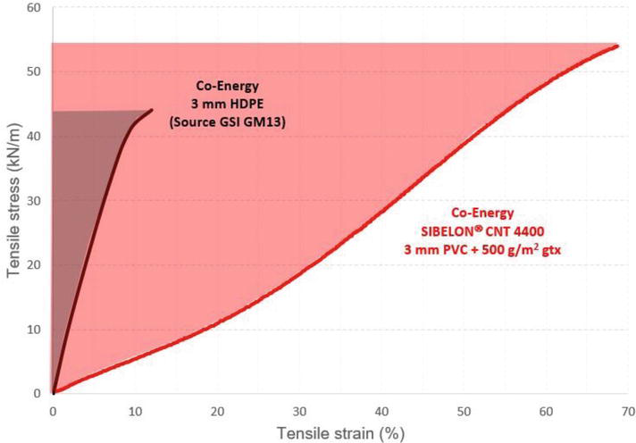
Figure 1.
Comparison between co-energy of a 3 mm thick HDPE geomembrane—the darker area—and of the geocomposite SIBELON® CNT 4400 (3 mm thick SIBELON® geomembrane heat bonded during fabrication to a 500 g/m2 nonwoven geotextile)—the red area.
Figure 1 clearly shows that the maximum allowable Co-Energy associated with the SIBELON® geocomposite is significantly greater than the Co-Energy associated with the HDPE geomembrane. As a result, the factor of safety with respect to a potential differential settlement is significantly higher for a SIBELON® geocomposite than for an HDPE geomembrane. It is important to note that a different geomembrane thickness would not produce a different result.
Successful performance of a geomembrane system depends on the physical and mechanical characteristics of the geomembrane, but also on the design and on the quality of the installation. A material with potentially optimal characteristics will still perform badly if the geomembrane system is not properly designed and installed. Bulletin 135 [2], provides guidelines for the design of geomembrane systems in different types of applications, and makes recommendations for Quality Control, installation procedures, specifications, and contracts, with the objective of ensuring long-lasting efficient water barrier. The sections that follow give an up-to-date overview of the various types of applications in new construction and in rehabilitation.
2. Design considerations
The design of a geomembrane system is closely connected to the characteristics of the dam and of its environment. In addition to the specific competencies related to geomembranes, the designer of the geomembrane system should have a thorough knowledge and understanding of the behavior of the dam and of the loads that will be acting on the geomembrane and possibly work in cooperation with the designer of the dam in case of new construction, and with the owner in case of rehabilitation.
“Environmental” loads, such as ultra-violet radiation, chemical attack by substances diluted in the water of the reservoir or by flora and fauna, and vandalism, influence the selection of the geomembrane type, thickness, and reinforcement, and to a certain extent the choice of whether to leave the geomembrane exposed or to cover it. The mechanical loads are the basis for the calculation of the anchorage system, which in turn is influenced by the type and thickness of the selected geomembrane.
2.1 Exposed geomembranes
The design of exposed geomembrane systems is based on the concept of keeping the geomembrane stable, taut to the dam face to avoid an insurgence of wrinkles and folds where stress concentration can occur, and capable of sustaining the applied loads. The static load of the water in the reservoir, associated with the conditions of the surface on which the geomembrane is laid, and the gravity load due to the weight of the geomembrane itself, will steer the selection of a material capable to resist puncture, burst, and tensile stresses. The dynamic loads due to uplift by wind when the reservoir is empty or lowered, by waves, differential deformations, and by earthquakes, are the parameters for designing the face anchorage system and the perimeter seals.
In the majority of cases, the worst-case scenario is uplift by wind, which will cause a deformation of the geomembrane and resulting stress on the face anchorage system. The equations developed for the face anchorage system [5, 6, 7] are based on the scheme shown in Figure 2.
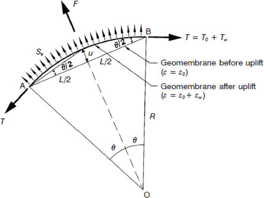
Figure 2.
Schematic representation of an uplifted geomembrane (from Giroud, 1995 and 1997).
Based on the scheme of Figure 2, being L the length of the undeformed geomembrane (Geomembrane before uplift) between adjacent anchorage points A and B, and 2θ the angle of the arc of the deformed geomembrane (Geomembrane after uplift), the equations are used to estimate, depending on the properties of the geomembrane used, the force Se applied to a unit width of lining between the two adjacent anchorage points, the displacement and subsequent strain T experienced by the geomembrane lining, and the resulting perpendicular and tangential stresses applied to the anchorage points.
When designing face anchorage systems for dams located in highly seismic areas, the worst-case scenario can be the maximum expected seismic event causing opening/widening of a crack when the reservoir is full, and the water pressure will force the geomembrane from its initial “supported” configuration into a deformed configuration, which must be verified to ensure that the strains in the geomembrane stay within the acceptable limits. An approach used by geomembrane systems designers assimilates the phenomenon of deformation due to water pressure to the phenomenon of deformation due to wind uplift. This same approach is used to verify the capability of external water stops to resist the displacements at joints between monolith blocks in RCC dams, and at peripheral joints and vertical joints between face slabs in Concrete Face Rockfill Dams (CFRDs).
Another critical component is the perimeter seal, which must maintain its watertightness against the applied water head, under any operating condition. Means to verify the watertightness of tie-down seals in static conditions in the laboratory and in the field are available. In case the area of the seal is susceptible to differential settlements (i.e., in dynamic conditions) since at present a test to verify watertightness in dynamic conditions has not yet been developed, design must use the available calculation methods to ensure that the seal is compatible with the expected event and that the geomembrane can bridge the differential settlement without sustaining the initial deformations and tensions induced by it, but only the deformations and tensions due to the hydrostatic pressure. To analyse at best which geomembrane can better perform in this respect, the concept of Co-Energy can be used, as mentioned in section 1.
Perimeter seals of the embedded type require a different approach: the watertightness of the seal cannot be verified nor calculated and shall rely on the engineering judgment of the designer for dimensioning the seal, and on the experience, craftsmanship, and Quality Control procedures of the installer for executing a correct seal. To achieve a watertight barrier, in case of a trench filled with low permeability material (e.g., clay) it will be necessary to correctly execute excavation, filling, and compaction of the trench, while in case of a slot filled with watertight resin, testing for pull-out, and control of correct filling of the slot and correct polymerisation of the resin, will be needed.
2.2 Covered geomembranes
Totally covered geomembranes are theoretically protected from environmental loads, with the possible exception of chemical attacks. For partially covered geomembranes, generally adopted for aesthetical reasons or to protect against fall of rocks at the abutments or vandalism in accessible areas, a face anchorage system may be needed where the geomembrane is exposed to wind action, depending on the extent of the exposed area and on the wind speed.
The type and thickness of the cover layer, different depending on the type of dam, are discussed in section 3. The design shall consider the uplift actions, and, in the case of embankment dams, the puncture loads exerted by the cover layer and the stability at sliding of the overall cover system, as further discussed. For the perimeter seals, the considerations made for the exposed systems generally apply.
3. Applications
Sections 3.1 to 3.3 address the waterproofing of the various categories of dams. Since the concepts and components are essentially the same, what is discussed here for full-face waterproofing applies also to waterproofing of parts of the dam where the leakage is expected/experienced. Section 3.4 discusses waterproofing of joints, and section 3.5 a special solution for underwater placement.
Geomembrane systems are the most sustainable waterproofing technology for dams: for all types of applications, the components have small volume and lightweight, and their installation does not require heavy equipment, so no large areas are required for site organisation, construction, or processing plants for materials. The environment and the communities will not be affected by excavations or by heavy transport, and transport to remote sites not accessible by vehicles will be feasible even by helicopter at sustainable costs. Since installation is quick and can be carried out in almost any weather condition, the project will be completed, the dam put in operation, and the site restored to its foreseen final conditions, or to its initial conditions in case of rehabilitation, in shorter times.
3.1 RCC dams
In new RCC dams, geomembranes are adopted as a water barrier for dams using an RCC mix with low cementitious content, assuming that the RCC provides the stability and the geomembrane placed at the upstream face permanently grants watertightness to the bulk RCC material, to the lift joints and construction joints, and to any thermal cracks or cracks that may develop due to other causes. With this philosophy of separating the static function from the waterproofing function, the cementitious content can be reduced, pozzolan and fly ash even eliminated, and requirements for placement and quality control of the RCC body can in general be relaxed. Lower cement content results in lower production of hydration heat, therefore the need to control the temperature with expensive cooling devices is reduced. GEVC (Grout Enriched Vibrated Concrete) or GE-RCC (Grout Enriched RCC) or CVC (Conventional Vibrated Concrete) at the upstream face can be deleted from the design, and horizontal joint treatment or the bedding mix on lift surface areas can be reduced. It is thus possible to place one RCC mix over the entire cross-section of the dam without the interferences caused by placement of bedding mix/CVC. The treatment of the lift joints may still be needed but only for shear strength and dam stability. Vertical waterstops and drains can also be eliminated because they are included in the geomembrane waterproofing and full-face drainage system. Local material more easily available and aggregates of less stringent properties can be used for the RCC mix, and less stringent construction and QA/QC procedures can be implemented. The overall result is that construction costs and construction time are remarkably reduced, and quicker filling and operation of the facility can be achieved.
The geomembrane can be installed on the completed upstream face and left in contact with the water of the reservoir (exposed geomembrane, first project in 1990), or the geomembrane can be embedded in precast concrete panels used as permanent formworks to build the dam (covered geomembrane sandwiched between the concrete of the panels and the RCC, first application in 1984).
3.1.1 Exposed geomembrane
The exposed configuration is the most frequently adopted worldwide and has been installed on very high RCC dams like Miel I (188 m, Colombia), Balambano (99.5 m, Indonesia), Olivenhain (97 m, USA), and Susu (90 m, Malaysia). The geomembrane liner must be kept stable and taut on the upstream face to avoid it being uplifted by wind and waves, and to minimise folds and wrinkles where stress concentration can occur. The state-of-the-art face anchorage system, discussed also in Bulletin 135 [2], consists of two stainless-steel profiles, the first one in the shape of a U that is secured to the upstream face, and the second one in a shape similar to the Greek letter Omega, which is installed at the overlapping of two adjacent vertical geomembrane sheets, fastened to the underlying U profile, and waterproofed by a geomembrane cover strip heat-seamed on the liner. In older projects, the U profile was embedded in the RCC lifts as they were being placed, so that one component of the anchorage system was already in place when the dam body had been completed. However, this method presented some drawbacks, and it was gradually substituted: since 2007, the U profiles are generally installed after RCC placement has been completed. The case history that follows discusses the typical details for face anchorage, peripheral anchorage, and drainage and monitoring systems of a recent project on a high RCC dam.
Susu dam in Malaysia is part of the Ulu Jelai Hydroelectric project commissioned by Tenaga Nasional Berhad (TNB), the largest power utility in Malaysia, for meeting the surge in demand for electricity at peak hours of the day. Susu RCC dam, 90 m high and about 512 m long at crest, was designed with an RCC mix of medium-low cementitious content (100 kg/m3 of cement and 80 kg/m3 of fly ash) and an upstream PVC geomembrane embedded in pre-cast concrete panels used as formworks to place the RCC (covered geomembrane system). This covered geomembrane solution had been used for the first time at Winchester dam, in Kentucky, in 1984. The major advantage of the covered geomembrane system is that the geomembrane is permanently shielded against potential environmental damage during its service life. However, the geomembrane is not shielded against the risk of damage during construction, which actually has been found to be the highest risk for the integrity of a geomembrane, and the exposed configuration has some additional advantages over the covered configuration: its efficient face drainage system at the design stage allows reducing uplift, and during service, it allows removing infiltration and saturation water behind the waterproofing liner, so that saturation levels and pore pressures in the dam are lowered, with beneficial effects on uplift pressures, on safety factors, on AAR phenomena, and on appearance at the downstream face. The drainage system, through measurement of drained water, allows monitoring of the performance of the waterproofing system on a continuous basis and can be associated with other systems (Optical Fibre Cables, piezometers) to refine the assessment of the overall behavior of the geomembrane barrier. An exposed geomembrane liner can be inspected, controlled, and if needed repaired from accidental damages, even underwater, over its service life. Based on these considerations, the original design was modified to an exposed drained geomembrane system, which allowed reducing the cement content and removing the fly ash.
The geomembrane liner is a SIBELON®CNT 4400 composite geomembrane, formed by a 3 mm thick SIBELON® geomembrane heat-bonded at fabrication to a 500 g/m2 non-woven needle-punched polypropylene geotextile. The geocomposite is fastened to the dam face along vertical lines of the well-known and afore discussed patented tensioning system of stainless-steel profiles, at regular 5.70 m spacing; like in all recent projects, the U profile is fastened by stainless-steel anchor rods embedded in chemical phials. The components of the drainage system are then installed: a high transmissivity drainage geonet is placed over the entire upstream face of the dam, and an additional band of geonet, 1 m high, is placed along the bottom perimeter of each of the three horizontal drainage sections, to act as drainage collector. Drainage discharge pipes and ventilation pipes are constructed to reach the two drainage galleries at elevations 470 m a.s.l. and 518 m a.s.l., and at crest. In total 10 drainage compartments, 13 drainage pipes, and 30 ventilation pipes maintain the drainage geonet at atmospheric pressure. The waterproofing liner is placed over the geonet and secured with the Omega profiles, as shown in Figure 3.
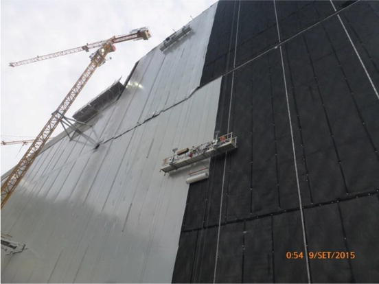
Figure 3.
Susu RCC dam. From right to left, the vertical U profiles fastened to the dam, the black drainage geonet placed between them on the upstream face, the waterproofing liner being placed on the geonet, some Omega profiles providing temporary anchorage against wind uplift, and at the extreme left the Omega profiles permanently fastened.
The drainage system constitutes Susu the monitoring system for the behavior of the geomembrane liner.
The geomembrane system, which extends from crest at elevation 547.90 m a.s.l. down to the grouting plinth, is divided into three horizontal sections terminating at elevation 519.00 m a.s.l., at elevation 471.00 m a.s.l., and at the intersection with the grouting plinth, respectively. In the section below elevation 474 m a.s.l., which is covered with backfill, the waterproofing geocomposite was protected with a double layer of geotextile for preventing damage during placement of the backfill.
The geomembrane liner must be sealed at peripheries by a watertight anchorage preventing water infiltration under the liner. The seal is watertight against water in pressure around the submersible perimeter, and against rain waves and snowmelt at crest. In RCC dams, submersible seals are of the tie-down type and made on conventional concrete: typically, they consist of a stainless-steel batten strip fastened with chemical anchors at 150 mm spacing, rubber gaskets and epoxy resin between the batten strips and the subgrade, and stainless-steel splice plates at abutting batten strips - at Susu, they are 80x8 mm in section and were placed along the spillway, the grouting plinth, the diversion conduits wall, and around the trash rack. At crest, the seals are more flexible stainless-steel batten strips, 50x3 mm, fastened with expansion anchors at 200 mm spacing, with a neoprene gasket placed between the subgrade and the waterproofing geocomposite - at Susu, they were placed at crest out of the spillway section and at the two junctions between adjacent horizontal sections, where watertightness was provided with a cover strip of a 3.00 mm thick SIBELON® C 3900 geomembrane, the same used to waterproof the Omega profiles.
Placement of the RCC, for a total of 731,000 m3, started in March 2014 and was completed in September 2015. Installation of the geomembrane system started in June 2015 and was completed in January 2016. Completion of the geomembrane system, for a total of 27,510 m2, was longer than usual because the installation was planned to match the construction schedule of the dam, therefore performed in three separate phases: in the first phase, prior to starting of construction of the dam body, the grouting plinth was waterproofed with a geocomposite that was later watertight connected to the geocomposite lining the upstream face, so to create a continuous impervious barrier down to the grout curtain; in the second phase, once construction of the dam body had been completed, the geomembrane system was installed on the dam face; finally, in the third phase installation of the geomembrane system was completed at the spillway, upon construction of the concrete ogee crest (Figure 4 at left). The reservoir was impounded shortly after the waterproofing works were completed.
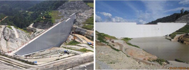
Figure 4.
View of the upstream face of Susu RCC dam at completion of the geomembrane system at spillway (left), and at start of impoundment (right).
3.1.2 Covered geomembranes
The covered configuration is used mainly in the USA where it was first conceived. During fabrication of the precast concrete panels that will be used as permanent formworks to place the RCC, the waterproofing geocomposite is placed on the fresh concrete, the geotextile side in contact with the panel, and vibrated (Figure 5 at left) to make the concrete impregnate the geotextile and thus attach the geocomposite to the panel. The geotextile also has an anti-friction function in case of differential movements, when if stresses are high it can detach from the geomembrane layer avoiding possible damage to the water barrier.
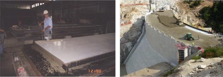
Figure 5.
Vibrating the concrete to attach the geocomposite to the precast panel (left), and Rizzanese RCC dam seen from the upstream: the bottom inclined section has not yet been lined, placement of RCC against the panels with embedded geocomposite + protection geotextile at the vertical section is ongoing (right).
After the first row of starter panels, watertight connected to the plinth, has been placed, a few rows of formwork panels are erected, and their junctions are waterproofed by strips of geomembrane of the same type used for the panels. A protection geotextile is then placed on the geocomposite, and the spreading and compacting of the RCC + upstream additional layers (GEVC, COV, or other) if any starts.
An interesting example, with a mixed configuration to the author’s knowledge adopted for the first time ever, is Rizzanese, a 40.5 m high RCC dam in the island of Corsica owned by EDF and used for hydropower. The dam has a central curved spillway section, made in RCC up to elevation 534 m, and in CVC at spillway and chute, and two lateral sections made entirely in RCC up to crest at elevation 546.5 m. The upstream face is inclined 1H/1V in the bottom part up to elevation 520 m, and vertical up to crest. EDF designed an RCC mix with 80 kg/m3 of cement, and a PVC geocomposite as an upstream water barrier on the entire upstream face. At the inclined section under elevation 520 m, the upstream face was made with prefabricated concrete elements, on which a geocomposite SIBELON® CNT 3750 (2.5 mm thick SIBELON® geomembrane heat-bonded at fabrication to a 500 g/m2 non-woven needle-punched polypropylene geotextile), was placed and covered by backfill placed on a 1000 g/m2 anti-puncture geotextile. At the vertical section above elevation 520 m, the upstream face was formed by the precast concrete panels discussed before, embedding a SIBELON® CNT 2800 geocomposite (2 mm thick SIBELON®geomembrane + a 200 g/m2 non-woven needle-punched polypropylene geotextile).
A 30 cm thick layer of CVC was placed between the panels and the RCC. At the spillway, the waterproofing system is prolonged to waterproof part of the vertical sides and the spillway sill, where it is covered by a sacrificial geomembrane to protect it against possible damage due to the heavy reinforcement and to concreting. The plinth has been waterproofed at the inclined section on its downstream and horizontal sides by SIBELON® C 3250, a 2.5 mm thick geomembrane, and at the vertical section only at the joints, with a Carpi patented external water stop system. Due to construction issues of the main contractor, the waterproofing system at the inclined section had to be installed after the vertical section had been completed. Waterproofing works were accordingly carried out in 2011 at the plinth and at the vertical section (Figure 5 at right) and in 2012 at the inclined section (Figure 6 at left).
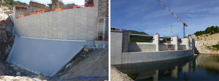
Figure 6.
Rizzanese dam. Placing the geocomposite at the inclined section before covering it with anti-puncture geotextile and backfill (left), and the impounded dam.
In total, the waterproofing system includes 1162 m2 at the inclined section and 2124 m2 at the vertical section.
3.2 Embankment and hardfill dams
In new embankment dams, the design concepts are to substitute a rigid upstream water barrier (e.g., concrete), or a traditional core (e.g., clay), with a highly deformable geomembrane, to construct a Geomembrane Facing Rockfill Dam/a Geomembrane Facing Earthfill Dam (GFRD or GFED), or a dam with a geomembrane core. Due to their tensile properties, geomembranes can make possible projects that would not be feasible with other systems, due for example to their capability to accommodating deformations that would exceed the resistance of a rigid water Barrier, or resisting differential movements occurring between the deformable dam body and the rigid ancillary structures maintaining the watertightness of the joints dam/concrete appurtenant structures.
An upstream geomembrane can enormously simplify the design of an embankment dam project: the dam can be constructed on highly deformable foundations, zoning of the dam can be modified to some extent, the upstream face can be constructed steeper so that the volume of fill is lesser, the diversion tunnel can be shorter and smaller, multiple lines of waterstops (case of CFRDs) can be reduced or eliminated, connections to concrete structures can be designed to accommodate large differential movements. Also, a geomembrane is an asset when suitable materials are not available at the site at acceptable costs (case of clay core dams).
Geomembranes provide additional advantages in terms of reduction of construction times, constraints, and costs. For example, installation/construction of the reinforced concrete face slabs in a CFRD, and placement of copper and PVC waterstops, can have a considerable impact on the overall construction schedule. In dams with clay or bituminous concrete cores, since the construction of the dam body and of the core are strictly related, the constraints imposed by the weather conditions, or any disruption in the placement of the filter material, or in placement/compaction of the impervious core, will affect the overall rate of construction of the dam. On the contrary, installation of a geomembrane system is practically unaffected by weather and can be scheduled in function of the schedule of construction and operation of the dam: the geomembrane can be installed when the dam is completed, or in the lower completed part of the dam while construction of the fill is ongoing in the upper part. In case of floods during construction, the already waterproofed lower part of the dam will be a barrier against the flood, increasing the safety of the project.
3.2.1 Exposed geomembranes
With an exposed system, zoning is not strictly required, a single fill material can be used, the thickness of the drainage layer can generally be reduced, and, depending on the design of the dam, it can act also as a base/anchorage layer for the waterproofing geocomposite. To maintain the liner stable on the upstream face there are basically three available configurations for the face anchorage system, depending on if the dam is raised with extruded porous concrete curbs as a finishing layer (Itá method), or if a traditional embankment is constructed.
When the upstream finishing layer is made by extruded porous concrete curbs, the face anchorage system is constructed by embedding in the curbs, while they are being raised, geocomposite anchor strips of the same type constituting the waterproofing liner. An anchor strip fixed to one curb overlaps the anchor strip fixed to the preceding curb, and the overlapping strips are heat-seamed to form continuous anchor lines. When the embankment has been raised to the final or pre-established height (case of staged construction), the waterproofing geocomposite sheets are deployed over the anchor strips and heat-seamed to them, to form a continuous watertight lining (Figure 7).

Figure 7.
Face anchorage with SIBELON® CNT geocomposite anchor strips embedded in curbs. At right the geocomposite being placed on the anchor strips at Nam Ou VI 88 m high rockfill dam in Laos.
This system has been applied in several projects, such as Nam Ou pictured below, Las Bambas GFRD in Peru (Figure 8), whose staged installation has so far reached 173 m, at the top part of Runcu 91 m high GFRD in Romania, at the top part of Rogun cofferdam in Tajikistan, whose staged installation has so far reached 80 m, and which will be incorporated in a 335 m high rockfill dam.
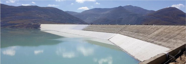
Figure 8.
Staged installation on curbs at Las Bambas dam, now reaching 173 m.
In dams where the finishing layer is not formed by extruded porous concrete curbs, depending on site-specific construction methods and type of supporting layers, the face anchorage system can be made by trenches or by deep anchors (Figure 9), positioned according to site-specific patterns that are a function of the uplift loads. If trenches are used, geocomposite anchor bands are embedded in trenches excavated in the compacted base layer, forming continuous anchorage lines. The trenches are generally backfilled with draining material (porous concrete or granular material), and the waterproofing geocomposite is heat-seamed to the anchor bands. The deep anchors face anchorage system consists of grouted anchors or earth “Duckbill” anchors that are driven into the embankment to provide the required pull-out resistance. The waterproofing geocomposite is anchored to the dam face by punching/clamping it over the anchors. A stainless-steel disk, an anti-puncture geotextile, and a geomembrane cover strip ensure watertightness where the anchors cross the waterproofing geocomposite.
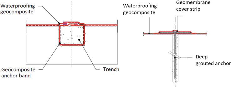
Figure 9.
Face anchorage by trenches and by deep grouted anchors.
The perimeter seals preventing water infiltration under the liner are as described for RCC dams when made on concrete. The bottom perimeter seal can also be made by embedding the waterproofing geocomposite in a trench that is then backfilled with low permeability material. The drainage system is site-specific and also in function of the construction procedure for the dam.
Examples of applications of anchorage by trenches are the bottom part of Runcu 91 m high GFRD in Romania, Murdhari 36 m high dam in Albania, Pico da Urze 31 m high dam in Portugal (Figure 10), Bulga 17 m high dam in Australia, and new reservoirs for pumped storage schemes in the Middle East and Morocco. Examples of applications of deep anchors are Filiatrinos 55 m high hardfill dam in Greece, Ambarau 21 m high hardfill dam in Congo and a section of the new Panama Canal 18 water-saving basins.
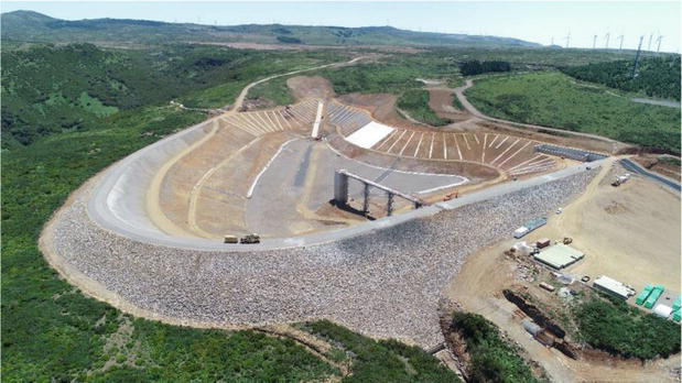
Figure 10.
Installation of waterproofing liner over anchor trenches at Pico da Urze dam.
3.2.2 Covered geomembranes
In the covered system, the geomembrane can be placed at the upstream face and be covered with concrete or granular ballast that will provide the face anchorage, or it can be embedded in the dam as a zigzag central core or upstream inclined core. The design shall allow the waterproofing geomembrane to freely deform, minimising tensions due to movements in the subgrade on which the geomembrane rests. The puncture loads exerted by the cover layer, and the stability at sliding of the overall cover system shall be considered. The geomembrane is generally sandwiched between two geosynthetic layers that act as anti-friction layers and provide anti-puncture protection from the adjacent materials.
Examples of upstream covered systems are Bovilla 91 m high dam in Albania (Figure 11 at left, unreinforced concrete cover), and Adret des Tuffes-Les Arcs 21 m high dam and reservoir in France (granular cover). A geomembrane core has been installed at Gibe III 50 m high rockfill cofferdam in Ethiopia, zigzag central geomembrane (Figure 11 at right) that was preferred to a clay core and to a concrete or asphalt concrete facing respectively because of lack of local availability of material suitable for an impervious core, for sake of safety, simplicity (it would allow the realization of an embankment of homogeneous rockfill, with optimization in construction times and costs), and timing, as it would allow completing the construction within a very short construction period. An upstream inclined core waterproofs the bottom 65 m high section of Rogun cofferdam in Tajikistan.
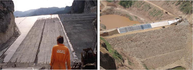
Figure 11.
At left Bovilla dam, at right Gibe III 50 m high cofferdam.
3.3 Concrete and masonry dams
In concrete and masonry dams, geomembranes are used to restore watertightness. They are always installed at the upstream face, in an exposed position unless site conditions require a partial cover layer. The state-of-the-art face anchorage system is the tensioning system described for exposed geomembranes in RCC dams. What is already discussed for these dams about perimeter sealing and drainage and monitoring systems applies also to these projects. Geomembrane systems that can be installed underwater are available for total and partial repair. They can be installed at any depth and provide long-term solutions when total or partial dewatering is not feasible or too costly.
3.4 Joints
Geomembrane systems can be conceived also for localised sealing, in form of “external waterstops”, in new construction, and as a repair method.
In new construction, external waterstops are applied over the monolith joints of RCC dams and over the peripheral and vertical joints of CFRDs. The main technical advantage as compared to conventional embedded waterstops is that, thanks to a typical 40-50 cm width of waterproofing geocomposite free to slide and distribute stresses, they can bridge large openings providing permanent protection against localised leakage.
The design of external waterstops generally includes one or more geosynthetic layers, of different kinds and thicknesses depending on the extent of the movements expected by the designers of the dam and on the maximum water pressure. A typical external waterstop (Figure 12) comprises
A single or multi-layered site-specific support/anti-puncture/drainage system, placed over the joint, in the area of the possible opening
A waterproofing layer, typically the geocomposite already discussed in the previous sections, placed over the support layer, and anchored independently from it, to cover the joint, over an area exceeding by at least 200–250 mm on each side the area of possible opening of the joint
A watertight perimeter seal of the tie-down type.
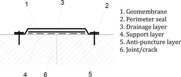
Figure 12.
Scheme of external waterstop (excerpt of ICOLD Bulletin 135).
The support/anti-puncture/drainage layers (Figure 13) avoid that the waterproofing geomembrane layer in contact with the water of the reservoir can be forced by the water pressure to intrude in the open joint. In dams located in seismic areas, the extent and frequency of the seismic cycles play an important role because they can cause an increase in water pressure that must be estimated and duly considered when designing the waterstop so that the admissible geomembrane elongation is not exceeded during and following the seismic event.
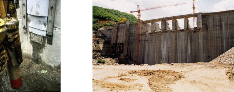
Figure 13.
Detail and view of external waterstops installed at monolith joints of Platanovryssi 95 m high RCC dam in Greece.
The most critical scenarios generally occur at the joints between a deformable embankment dam body and a rigid concrete appurtenance, or at construction joints of adjacent structures that may be subject to differential displacements, or in new CFRDs where the peripheral joint between the plinth and the face slabs is expected to have openings that will exceed the strength of the embedded waterstop, and therefore an additional waterproofing barrier is needed for safe operation. At such locations, it may be necessary to allow for an additional length of material so that the geomembrane liner can bridge the joint without sustaining the initial deformations and tensions induced by the opening of the joint, but only the deformations and tensions due to the hydrostatic pressure. The extra length can be created by placing under the waterproofing geomembrane liner a thick double-folded geotextile, or by inserting the external waterstop into a slot/recess formed at the joint. The extra length reduces the strain on the waterproofing geomembrane and ensures that the waterstop deforms sufficiently to remain in contact with the surface on which it rests. In case the expected openings are very large, say in the order of tens of centimeters, the support layer is a high-tech textile (Figure 14) with a high modulus of elasticity and high tensile strength, which develops minimum elongations and high tensions, and thus restrains the deformation and consequently the tensions in the overlying waterproofing geomembrane.
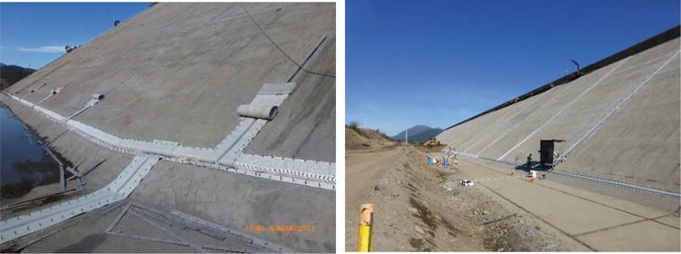
Figure 14.
High-tech support textile and waterproofing geocomposite at Angostura 32 m high 1.6 km long concrete face gravel dam, Chile. External waterstop on peripheral and vertical joints designed to resist joint openings up to 300 mm.
The same concept (support/anti-puncture/drainage layers + waterproofing layer + watertight perimeter sealing) is used in the repair of failings joints and cracks, where conventional sealing methods, such as grouting and injections, often require recurrent interventions and put a strain on the maintenance costs and may not be adequate in case of large openings, which on the contrary geomembrane systems can accept.
Similar to other repair methods with geomembranes, also external waterstops have been adapted for underwater applications.
3.5 Special solution for underwater placement
A special solution for underwater placement, recently developed for repair of canals without stopping or reducing the water flow, is applicable also in new construction. This innovative system, the SIBELONMAT®, consists of two geomembranes connected to form a mattress, which is placed underwater covering the whole embankment to be watertightened, is temporarily anchored, and then filled with cement grout. The bottom geomembrane provides watertightness, the cement grout provides permanent anchorage by ballast, and the upper geomembrane provides containment for the fresh grout and enhances the hydraulic efficiency of the mattress due to its smoothness. The mattresses, prefabricated in panels of 10 m width and predefined length (Figure 15 at left), are connected underwater by watertight heavy-duty zippers. The system has proven its efficiency in a few pioneer pilot projects in flowing water (Figure 15 at right), which have shown that as more experience is acquired, improved design can be developed. Already under study are new components and equipment to improve and industrialise the system, with the objective of reducing installation times and costs. Such a system could be used for underwater lining of embankment dams and for blanketing, opening new scenarios that can potentially provide huge savings to the owners.
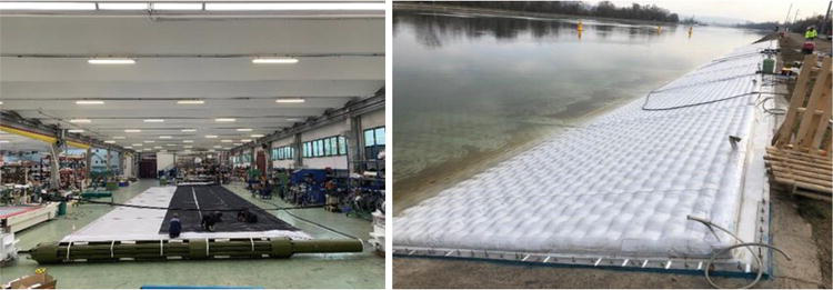
Figure 15.
The SIBELONMAT® panels under fabrication (at left) and injected and sealed at Kembs dike, part of the Grand Canal d’Alsace navigation canal in France.
4. Conclusions
Geomembrane systems are designed to allow the construction of safe dams, including dams of considerable height, with simple procedures that accommodate demanding scenarios and schedules, with sustainable environment-friendly solutions. They allow completing the waterproofing system for the dam in a shorter time and at lower costs than traditional water barriers. In form of external waterstops, they provide and maintain watertightness under loading conditions that would not be acceptable for embedded waterstops. They are a mature and reliable technology, as proven in hundreds of projects worldwide. They can be installed underwater, providing a long-term solution with no environmental impact.
References
- 1.
Giroud, JP, Perfetti, J. Classification des textiles et mesure de leurs propriétés en vue de leur utilisation en géotechnique. In: Proceedings of the International Conference on the Use of Fabrics in Geotechnics; Paris; 1977. p. 345-352 - 2.
International Commission on Large Dams. Ed. Bulletin 135, Geomembrane Sealing Systems for Dams: Design Principles and Review of Experience. Paris; 2010. p. 464 - 3.
Giroud JP, Soderman KL. Comparison of geomembranes subjected to differential settlement. Geosynthetics International. 1995; 2 (6):953-969 - 4.
Giroud JP. Quantification of geosynthetic behavior. Geosynthetics International. 2005; 12 (1):2-27 - 5.
Giroud JP, Pelte T, Bathurst RJ. Uplift of geomembranes by wind. Geosynthetics International. 1995; 2 (6):897-952 - 6.
Zornberg JG, Giroud JP. Uplift of geomembranes by wind: Extension of equations. Geosynthetics International. 1997; 4 (2):187-207 - 7.
Giroud JP, Gleason MH, Zornberg JG. Design of geomembrane anchorage against wind action. Geosynthetics International. 1999; 6 (6):481-507