Open Access is an initiative that aims to make scientific research freely available to all. To date our community has made over 100 million downloads. It’s based on principles of collaboration, unobstructed discovery, and, most importantly, scientific progression. As PhD students, we found it difficult to access the research we needed, so we decided to create a new Open Access publisher that levels the playing field for scientists across the world. How? By making research easy to access, and puts the academic needs of the researchers before the business interests of publishers.
We are a community of more than 103,000 authors and editors from 3,291 institutions spanning 160 countries, including Nobel Prize winners and some of the world’s most-cited researchers. Publishing on IntechOpen allows authors to earn citations and find new collaborators, meaning more people see your work not only from your own field of study, but from other related fields too.
All aluminum micro-channel heat exchanger (MCHE) is used in automobiles and HVAC because of their low density and relatively high strength. While exhibiting significant general corrosion resistance, the MCHE or aluminum alloy is susceptible to various forms of localized corrosion, such as crevice and pitting corrosion. Crevice corrosion also occurs on the contact surface of the fin and tube for an all-aluminum microchannel heat exchanger. An electrochemical impedance spectroscopy (EIS) examination was performed on aluminum MCHE in corrosive conditions with varying sodium chloride and ammonium sulfate concentrations. The electrolytes discussed in this book chapter have pH values between 4.0 and 5.8, closer to neutral conditions commonly seen in various atmospheres. This work employs high-fidelity conjugate heat transfer simulations to analyze a microchannel heat exchanger system with fins and tubes in crossflow to investigate the possibility of crevice corrosion in the MCHE alloy. A predicted flow field can identify crevices between fins and tube surfaces. These crevices are typically linked with regions of low velocity.
Austin Peay State University, Clarksville, TN, USA
*Address all correspondence to: ahmedh@apsu.edu
1. Introduction
Recently, the effectiveness and functionality of thermal management systems have become crucial in various industries, such as automotive, aircraft, and HVAC systems. Among the various components that play a pivotal role in the efficacy of these systems, the heat exchanger stands out for its importance in transferring heat between two or more fluids. All-aluminum microchannel heat exchangers (MCHXs) are increasingly popular because of their excellent thermal conductivity, low weight, and small size, providing notable benefits compared to conventional heat exchanger models. Nevertheless, all-aluminum MCHXs have several obstacles while being widely adopted and having intrinsic advantages. Corrosion is a significant factor impacting the durability and dependability of MCHEs. Corrosion is a natural process that slowly deteriorates materials by electrochemical reactions with their surroundings, which can significantly reduce the effectiveness and lifespan of aluminum MCHEs. Given the critical role of these heat exchangers in various applications, understanding the mechanisms of corrosion, its effects on the performance of MCHEs, and developing strategies to mitigate corrosion is paramount.
This chapter of the book explores the study of corrosion in all-aluminum microchannel heat exchangers. The goal is to thoroughly examine the many types of corrosion that affect these heat exchangers, such as pitting, crevice, and intergranular corrosion. Most heat exchanger failures are caused by the inhospitable environments in which they are used. Crevice corrosion is caused by the outflow of salt and fouling [1]. In their study, Yoshino et al. [2] looked into intergranular corrosion (IGS), which happens when the fin interacts with the microstructure and chemical makeup. The region susceptible to crevice corrosion collects deposits, which trap moisture for prolonged durations, resulting in elevated moisture levels. The region between the fin and tube is particularly susceptible to crevice corrosion due to limited fluid movement or extremely low fluid speeds. Stagnant areas harbor corrosive salts and other impurities that give rise to pits of different dimensions, ultimately forming perforated tubes. Faes et al. [3] found a specific type of corrosion occurring in heat exchangers. Aluminum alloys develop a protective coating that is usually susceptible to pitting [4]. Pits form as a result of surface damage to the protective layers. Over time, these pits become increasingly noticeable and cause the heat exchanger tube to develop holes. The formation of this pitting is triggered by corrosion byproducts in the surrounding atmosphere. High chloride concentrations, elevated temperatures, and low pH values can cause pitting corrosion.
The chapter will also investigate the most recent corrosion prevention and control measures developments. Material selection, protective coatings, anodic protection, and design optimization are crucial for improving the durability of all aluminum MCHXs against corrosion. The aim is to provide engineers, researchers, and practitioners with the expertise and resources to create, choose, and maintain all-aluminum microchannel heat exchangers capable of enduring corrosion difficulties. This chapter demonstrates the presence of a zero velocity-caused corrosion hot spot or crevice area close to the junction of the fin and solid. Moreover, this study includes several fin shapes (louver and saw) in combination with a circular microchannel heat exchanger (MCHE). In addition, a projected flow field is utilized to identify locations where corrosion is likely to occur rapidly. These locations are typically characterized by low speeds, making them prone to crevice corrosion-induced material breakdown. This breakdown often results in pitting, eventually leading to perforation and subsequent leakage of MCHEs. The experimental findings of the EIS test are displayed for MCHE tubes immersed in electrolytes with varying chloride and sulfate concentrations.
Comprehending the corrosion mechanisms of aluminum alloys is essential for strengthening their design, durability, and application range. Corrosion is natural when a pure metal transforms into a chemically stable compound such as oxide, hydroxide, or sulfide. Corrosion is the slow deterioration of materials, typically metals, due to electrochemical reactions with their surroundings. Corrosion in aluminum alloys is a significant concern due to its potential to cause catastrophic failures if poorly controlled. This chapter explains the several corrosion mechanisms that aluminum alloys might experience, such as pitting corrosion, crevice corrosion, intergranular corrosion, and exfoliation corrosion. Adding alloying metals like copper, magnesium, zinc, and silicon enhances aluminum’s mechanical and physical characteristics but can also increase its vulnerability to certain types of corrosion. Copper significantly increases aluminum’s strength and susceptibility to galvanic corrosion when in contact with different metals. Similarly, the presence of magnesium in aluminum alloys can result in pitting corrosion in conditions that contain chloride.
2.1 Localized corrosion
Localized corrosion often involves the following chronological steps:
Reactive species adhere to aluminum oxide film.
The adhered species engage in a chemical reaction with precipitated aluminum hydroxide, Al(OH)3, or aluminum ions.
Dissolution leads to a thinner oxide film and infiltration of reactive species into the oxide film.
Pitting expansion involves reactive species directly assaulting the aluminum.
During the second step, the competitive process, chloride ions, water molecules, and hydroxyl ions vie to adsorb onto the aluminum surface. The surface would become less active if the aggressive species lost the adsorption competition [5].
2.2 Pitting corrosion
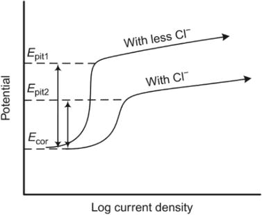
Pitting corrosion is the result of localized corrosion forming holes. This occurs when the passive oxide layer breaks down. The initial stage of pitting corrosion is the breakdown of passivity, known as pitting initiation, which includes three mechanisms. (i) Adsorption and adsorption-induced mechanisms involve corrosive species, like chloride ions, attempting to adhere to the hydroxyl group positions on the surface. (ii) Ions migrate through the metal-oxide interface. (iii) The aggressive species degrade the protective film and substitute the existing ions, producing a new film with the aggressive ions [6, 7, 8, 9, 10]. After the formation of the pit, propagation happens, leading to autocatalytic growth of the pit. The autocatalytic reaction causes the formation of cavities on the metal surface [11]. The pitting potential, Epit, indicates the likelihood of pitting corrosion, and Figure 1 shows that a lower concentration of chloride ions leads to a higher Epit. This results in increased resistance to pitting corrosion. A more significant disparity between the corrosion potential, Ecor, and Epit results in increased resistance to pitting corrosion.
Figure 1.
Examples of an anodic polarization curve and how the concentration of Cl-affects Epit [6].
2.3 Crevice corrosion
Metals and alloys exposed to corrosive environments may develop crevice corrosion, which is a localized form of corrosion. The vulnerability of all-aluminum microchannel heat exchangers to crevice corrosion is due to their design and operating conditions. The narrow microchannels, typically less than 1 mm wide, are susceptible to the buildup of corrosive substances like chlorides and sulfates, usually present in atmospheric or cooling fluids. These chemicals and moisture provide a highly reactive electrolytic environment in the crevices. Over time, localized corrosion may significantly weaken the heat exchanger’s structural integrity and thermal efficiency. Additionally, the aluminum alloys used in these heat exchangers have different resistance levels to crevice corrosion, mainly influenced by their composition and protective oxide layers. Despite this, they provide heat transfer efficiency and weight reduction benefits. Alloy composition, manufacturing procedures, and operating conditions like temperature and pH influence the start and development of crevice corrosion [12].
Nasrazadani et al. [13] conducted experiments that demonstrated crevice and pitting corrosion along the fin and solid surface of a microchannel heat exchanger (MCHE). The experimental data demonstrates that crevice corrosion occurs at the interface between the fin and solid surfaces.
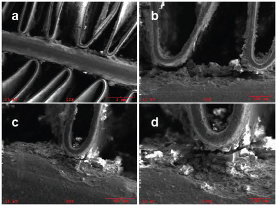
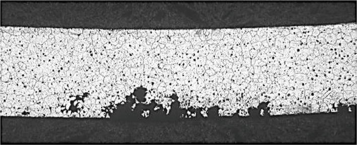
The corroded MCHE samples were examined using scanning electron microscopy (SEM). After enduring a corrosive environment in the corrosion chamber for over 104 days, the MCHE samples were collected [13]. Figure 2 shows a deteriorated crevice region situated at the confluence of the fin and solid surfaces. This phenomenon is distinct from other types of failure, such as vibration failure, in which the metal breaks suddenly without pits. Crevice corrosion is more likely to happen in relatively low- or zero-velocity situations. Regulating the velocity is essential to maintaining enough flow, minimizing stagnation, and inhibiting corrosion.
Figure 2.
SEM micrographs of MCHE sample after around 104 days of exposure to corrosive electrolyte [13].
Ahmed et al. [14, 15, 16] examined the thermal efficiency and corrosion of a microchannel heat exchanger (MCHE) with three distinct fin shapes (louver, step, and saw) in combination with a circular microchannel by numerical analysis.
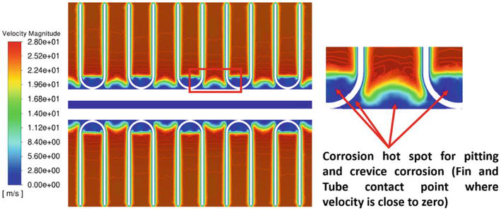
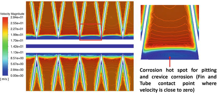
This work evaluates the crevice corrosion risk related to various fin geometry in MCHEs using high-fidelity conjugate heat transfer models. Figures 3 and 4 display the velocity curve around the circular MCHE. At midplane, the boundary layer near the solid side tube shows zero or little velocity. The thickness of this separated zone displays variations in the spanwise direction, leading to a bigger separated region that is enclosed by each fin, in contrast to the region situated in the gap between two consecutive fins. The change of the wake field in the spanwise direction is caused by the interaction between the fins and the flow field, resulting in a decrease in velocity within the region bounded by each fin. As the crossflow diverges from the tube and fin assembly, the velocity accelerates inside the gaps, reaching speeds of around 28 meters per second. The velocity is around 70% greater than the entrance velocity. These low-velocity regions are susceptible to pitting and crevice corrosion. Pitting and crevice corrosion are both types of localized corrosion that cause fast penetration at tiny locations. To prevent different forms of corrosion, it is crucial to maintain adequate flow velocities to prevent stagnation or the accumulation of solid materials. Pitting corrosion is more likely to happen during shutdown periods with no flow, creating favorable conditions for concentration cell development. The corrosion hot spot area may be identified by calculating the low-velocity zone (blue region) volume per fin pitch.
Figure 3.
Stagnation region identification for louver-shaped fin geometry at midplane [15, 16].
Figure 4.
Stagnation region identification for saw-shaped fin geometry at midplane [15, 16].
2.4 Intergranular corrosion
When the crystal and its grain do not undergo evident destruction, intergranular corrosion may occur along the grain boundary of a metal and its alloys. This kind of corrosion is caused by the absence of visible destruction. This significantly diminishes the mechanical characteristics of a metal and its alloy [17]. The variation in microstructure grain boundaries between aluminum and its alloys leads to differences in electrochemical potential creation and electron exchange. Intergranular corrosion begins due to pitting corrosion and rapidly propagates along the grain boundary [18]. Intergranular corrosion may occur when the grain boundary of the metal and its alloy becomes active. The condition involves altering the components of the metal alloys at their grain boundaries, either by increasing or lowering them.
Conversely, the grain boundary requires an electronegative region. The portion with higher electronegativity will experience corrosion first [19]. Intergranular corrosion may occur when high-purity aluminum alloys such as Al-Mg, Al-Cu, and Al-Zn-Mg are exposed to severely acidic environments or high-temperature water. Maintaining adequate flow velocities is crucial to preventing different forms of corrosion by avoiding stagnation or solid material accumulation.
Figure 5 depicts intergranular fractures in aluminum tubes [20]. Researchers began to pay greater attention to intergranular corrosion in the mid-twentieth century. Three primary theories of intergranular corrosion were proposed.
Galvanic corrosion happens because of the difference in electrochemical potential between the alloy’s crystalline lattice and the anodic grain boundary. This leads to more intergranular corrosion [21].
This could happen because of the difference in breakdown potential between the grain boundary and the solute atom depletion zones (SDZ) [22].
When the precipitated phase dissolves at the grain boundary, it creates an enclosed environment, leading to intergranular corrosion [23, 24].
Figure 5.
Intergranular corrosion of an aluminum tube [20].
Most intergranular corrosion studies have focused on one or more of the ideas above. Studying the grain boundary precipitation phase requires a galvanic coupling approach. A galvanic couple is created between pure aluminum and the composition of grain boundary precipitation [23, 24].
It then analyzes the polarization curves and evaluates the present level of corrosion. Researchers can determine how corrosion works at different potentials by looking at the breakdown potential between the SDZ and the lattice [22].
This study focused on investigating the corrosion resistance of the Al-3102 microchannel heat exchanger tube in various chloride and sulfate-concentrated electrolytes. EIS is a method used to assess the impedance of an electrochemical system, which can indicate the effectiveness of a coating in protecting the substrate. A high-quality protective barrier will exhibit capacitive characteristics in its bode plot, whereas a damaged coating will display resistive properties at the low-frequency range of the EIS spectrum. Electrochemical systems, such as surfaces composed of coatings or metals undergoing corrosion, exhibit characteristics akin to those of basic electrical circuits [25]. Hence, EIS data is usually analyzed using an equivalent electrical circuit model. This procedure is called equivalent circuit analysis (ECA) [11]. Provided that the model is physically representative of the actual measuring system, the variation of the model components can be tracked over time so that changes in the physical system can be quantified as a function of time [26].
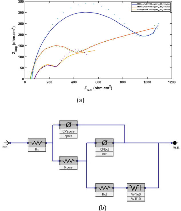
One possible interpretation of this model assumes that the coating has undergone partial delamination from the metal substrate and that the resulting delaminated region is filled with a solution. The double-layer capacitance, CPEct, marks the boundary between the solution pocket and the metal surface. It is linked in parallel to a charge transfer reaction element controlled by kinetics, which is shown by the charge transfer resistance Rct. The term “polarization resistance” is occasionally used to refer to the resistive corrosion product layer on the metal plate, which is denoted as Rpore. The schematic illustrating the model of the circuit is presented in Figure 6(b). In Figure 6(a), a second semicircle becomes visible in the Nyquist plot. The initial semicircle intersects the real axis near the origin at the Rs value and terminates at a value of Rpore+Rs, marking the starting point of the second semicircle. The second semicircle terminates at a value equal to the sum of Rpore, Rs, and Rct. The corrosion rate is inversely related to Rct. These equivalent electrical circuit (EEC) models show the impedance spectra for oxide products that form during corrosion reactions on metal surfaces, anodizing coatings, or Zn-coated metals that have been exposed to corrosive solutions. The capacitance of the oxide film, referred to as CPEpore, is parallel to the oxide resistance, Rpore. Both components are connected in parallel series to the Randles circuit (RC), which contributes to the electrical responsiveness of the double-layer interface. Based on Figure 6(a), the diameter of the second semicircle is larger in EIS 2 compared to EIS 1. The reason for this is that both EIS 1 and EIS 2 exhibit a similar elevated chloride concentration; however, EIS 2 has a greater pH value.
Figure 6.
(a) Nyquist plot for high chloride at different pH levels, high sulfate solution, and (b) equivalent circuit model used to analyze the experimental data [16].
The electrochemical impedance spectroscopy (EIS) of the aluminum alloy electrode exhibited the presence of Warburg impedance and a relatively small capacitive arc. This suggests that the electrode process is influenced by both the charge transfer step and the oxygen diffusion step. Consequently, the EIS in these two media was analyzed using the equivalent circuit depicted in Figure 6(b) [27].
Figure 6(b) depicts the equivalent circuit, which is specifically created to detect and evaluate the typical components of the EIS system. For instance, the spread of molecules or redox species might cause an additional resistance called the Warburg impedance (W), which varies depending on the frequency. The Warburg impedance (W) exhibits a modest value when the frequency is high, but it increases at low frequencies. This is because the redox molecules experience a greater resistance to diffusion at lower frequencies. The impact of a diffusion process taking place at the interface between the electrode and the electrolyte is what causes the presence of Warburg resistance. In addition, a constant-phase element (CPE) is included in the equivalent circuit to represent the non-ideal behavior of the capacitance. The Al-3102 sample’s polarization resistance (Rp) is the resistance it exhibits when the Zn inhibitor is present. Table 1 provides a description of the electrochemical impedance spectroscopy (EIS) experiment utilized in this investigation. The polarization resistance is directly associated with the occurrence of corrosion on the surface of the metal. Consequently, a greater Rp value indicates a higher level of resistance to corrosion.
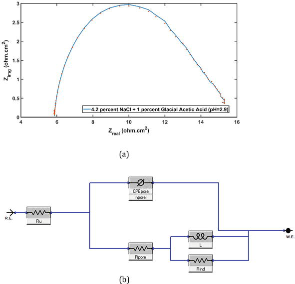
Figure 7(a) depicts the inductive loop in the low-frequency range for the SWAAT solution. Deciphering the inductive loop is a significant challenge when utilizing EIS for corrosion systems, both in terms of practical and theoretical perspectives. Most of the impedance spectra from experiments with an inductive loop in the low-frequency range have been found at Ecorr in acidic media with inhibitors present. Figure 7(b) depicts the equivalent circuit, which is specifically created to detect and evaluate the typical components of the EIS system. The presence of the capacitive loop in acidic solutions might be attributed to the dielectric characteristics of the oxide coating [28, 29, 30].
Figure 7.
(a) Nyquist plot for SWAAT solution and (b) equivalent circuit model used to analyze the experimental data [16].
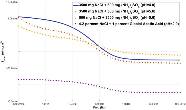
Figure 8 displays a graph that plots the frequency against the impedance, allowing for the determination of the capacitance of the electrochemical systems. Figure 8 is commonly referred to as the bode plot.
Figure 8.
Bode plot for high chloride at different pH levels high sulfate and SWAAT solution [16].
Aluminum alloys are prone to localized corrosion, so these alloys are usually safeguarded with a coating system to offer barrier protection against harsh conditions. These alloys are prone to localized corrosion because intermetallic particles exhibit significantly different electrochemical properties than the aluminum matrix [31, 32]. Coatings can be applied to the surface to shield the metal from a severe environment. Coatings do not enhance mechanical strength but are a barrier between the material and the corrosive electrolyte [33]. They are often classified as metallic, organic, or inorganic coatings. Chromate conversion coatings (CCC) are utilized in aluminum alloys for protective purposes. The chromate conversion coating is an adequate surface preparation for protecting aluminum alloys. Due to its simplicity, affordability, and corrosion-resistant properties, this material is utilized in various applications [34, 35, 36, 37]. The creation of CCC and its protective mechanisms considerably enhance the efficiency of aluminum alloys as surface preparations. This pretreatment is commonly used in a bath containing acid and chromium (VI) ions. The protective layer consists of two unique layers: a thick and porous outer layer and a barrier layer between the coating and the metal surface beneath it [38, 39, 40, 41, 42, 43]. Campestrini et al. [37] suggested a three-stage formation process. The metal surface is initially activated by reducing the original aluminum oxide layer, which enables the aluminum to dissolve at the contact. Chromium reduction initiates upon activation of the aluminum surface, leading to the solution’s saturation with trivalent chromium. Chromium oxide starts to precipitate on the surface when supersaturation takes place. The final stage involves applying chromium (III) hydroxide to the entire surface and allowing the coating to develop. The surface is covered with round chromium oxide particles, but the layer is porous, making other processes happen and making the chromate layer thicker.
Metallic coatings can be used as a base material in several applications, including hot dipping, electroplating, spraying, cementation, and diffusion [44]. Various parameters, including the necessary corrosion resistance and the expected lifespan of the coating, determine the selection of the coating process type. Metals, including nickel, zinc, lead, tin, aluminum, cadmium, and chromium, are commonly used as coatings on substrates made of different materials. Paints, lacquers, resins, and plastic linings are categorized as organic coatings [39]. They are often designed to have excellent impermeability and impede corrosion, potentially including catholically protecting colors. Inorganic coatings can be categorized into two groups [30]. The protected substrate is coated with hydraulic cement, ceramics, carbon, silicates, and glass. Different treatments change the oxide layer’s natural properties, making it less corrosion-resistant, into a new protective film or metallic oxide that is better at resisting corrosion in that specific operational setting. Examples include anodizing, nitriding, and phosphatizing.
Various coatings have been applied to heat exchangers to shield the heat transfer surface from corrosive environments [40, 41]. Moreover, coatings can have a distinct function in preventing corrosion. Wang et al. [42] conducted experiments on hydrophilic coatings to enhance condensate drainage in fin-and-tube heat exchangers. Improved drainage might decrease the pressure drop by as much as 40%. Hydrophilic coatings have been effectively used in dehumidifying heat exchangers [43]. Hydrophobic coatings have been tested on heat exchangers. For instance, Das et al. [44] utilized these coatings to enhance dropwise condensation in a condenser.
An analysis using numbers to examine how corrosion affects fins and tubes was conducted in this study, using all aluminum MCHE with various fin shapes. This chapter illustrates the pitting and crevice corrosion areas and predicts the corrosion hot spot by considering the outside airflow. The results of this study will aid in the design of a more corrosion-resistant fin form. Because EIS is a non-destructive test, there were no notable visible indications of corrosion on the sample that was evaluated. EIS measurements showed substantial physical alterations in the Zn covering. The results support that Zn coating systems safeguard aluminum alloys because Zn is more anodic than aluminum in the galvanic series. The maximum Rp value is obtained with high chloride concentrations and a low pH. An inductive loop was detected in the low-frequency range of the SWAAT solution.
References
1.Michels HT, Kirk WW, Tuthill AH. The influence of corrosion and fouling on steam condenser performance. Journal of materials for energy systems. Dec 1979;1(3):14-33
2.Yoshino M, Iwao S, Edo M, Chiba H. Mechanism of intergranular corrosion of brazed Al–Mn–Cu alloys with various Si content. Materials Transactions. 2017;58(5):768-775. DOI: 10.2320/matertrans.L-M2017808
3.Faes W, Lecompte S, Ahmed ZY, Van Bael J, Salenbien R, Verbeken K, et al. Corrosion and corrosion prevention in heat exchangers. Corrosion reviews. 2019;37(2):131-155. DOI: 10.1515/corrrev-2018-0054
4.Revie RW. Corrosion and Corrosion Control: An Introduction to Corrosion Science and Engineering. UK: John Wiley & Sons; 2008
6.Yasakau KA, Zheludkevich ML, Ferreira MG. Role of intermetallics in corrosion of aluminum alloys. Smart corrosion protection. Intermetallic Matrix Composites. 2018:425-462. DOI: 10.1016/B978-0-85709-346-2.00015-7
7.Foley R. Böhni H. Localized corrosion of aluminum alloys: A review. Houston, Tex: Corrosion. 1986;42(5):277-288. DOI: 10.5006/1.3584905
8.Seyeux A, Maurice V, Marcus P. Breakdown kinetics at nanostructure defects of passive films. Electrochemical and Solid-State Letters. 2009;12(10):C25. DOI: 10.1149/1.3186644
9.Strehblow HH. Nucleation and repassivation of corrosion pits for pitting on iron and nickel. Materials and Corrosion. 1976;27(11):792-799
10.Akpanyung KV, Loto RT. Pitting corrosion evaluation: A review. Journal of Physics: Conference Series. 2019;1378(2):022088. DOI: 10.1088/1742-6596/1378/2/022088
13.Nasrazadani S, Vaughan H, Ellerbrock D, Martin-Callizo C. Development of a new accelerated corrosion test for all-Aluminum microchannel and tube and fin heat exchangers—Part II: Chamber study. ASHRAE Transactions. 2020;126(2):8-15
14.Ahmed H, Sadat H, Nasrazadani S. High-fidelity conjugate heat transfer simulation of micro-channel heat exchanger. Journal of Advanced Research in Fluid Mechanics and Thermal Sciences. 2023;106(1):165-181. DOI: 10.37934/arfmts.106.1.165181
15.Ahmed H, Nasrazadani S, Sadat H. Comparison of thermal effectiveness and crevice corrosion risk of fin geometry on all-aluminum microchannel heat exchangers. Journal of Advanced Research in Fluid Mechanics and Thermal Sciences. 2023;105(2):192-203. DOI: 10.37934/arfmts.105.2.192203
16.Ahmed H. Structural design and its impact on thermal efficiency and corrosion of all-aluminum microchannel heat exchangers [Dissertation]. Denton: University of North Texas; 2023. DOI: 10.12794/metadc2179279
17.Sinyavskii VS, Ulanova VV, Kalinin VD. On the mechanism of intergranular corrosion of aluminum alloys. Protection of Metals. 2004;40:481-490. DOI: 10.1023/B:PROM.0000043067.38199.95
18.Minoda T, Yoshida H. Effect of grain boundary characteristics on intergranular corrosion resistance of 6061 aluminum alloy extrusion. Metallurgical and Materials Transactions A. 2002;33:2891-2898. DOI: 10.1007/s11661-002-0274-3
19.Kim SH, Erb U, Aust KT, Palumbo G. Grain boundary character distribution and intergranular corrosion behavior in high purity aluminum. Scripta Materialia. 2001;44(5):835-839. DOI: 10.1016/S1359-6462(00)00682-5
20.Ifezue D, Tobins FH. Corrosion failure of aluminum heat exchanger tubes. Journal of Failure Analysis and Prevention. 2015;15:541-547. DOI: 10.1007/s11668-015-9973-0
21.Brown RH, Fink WL, Hunter MS. Measurement of irreversible potentials as a metallurgical research tool. Transactions of the AIME. 1941;143:115-122
22.Galvele JR, de De Micheli SM. Mechanism of intergranular corrosion of Al-Cu alloys. Corrosion Science. 1970;10(11):795-807. DOI: 10.1016/S0010-938X(70)80003-8
23.Buchheit RG, Moran JP, Stoner GE. Electrochemical behavior of the T1 (Al2CuLi) intermetallic compound and its role in localized corrosion of Al-2% Li-3% Cu alloys. Corrosion. 1994;50(2):120-130. DOI: 10.5006/1.3293500
24.Kowal K, DeLuccia J, Josefowicz JY, Laird C, Farrington AG. In situ atomic force microscopy observations of the corrosion behavior of aluminum-copper alloys. Journal of the Electrochemical Society. 1996;143(8):2471. DOI: 10.1149/1.1837033
25.Pardo A, Otero E, Merino MC, López MD, Utrilla MV, Moreno F. Influence of pH and chloride concentration on the pitting and crevice corrosion behavior of high-alloy stainless steels. Corrosion. 2000;56(04):19-21
26.Loveday D, Peterson P, Rodgers B. Evaluation of organic coatings with electrochemical impedance spectroscopy. JCT Coatings Tech. 2004;8:46-52
27.Sowa M, Simka W. Electrochemical impedance and polarization corrosion studies of tantalum surface modified by DC plasma electrolytic oxidation. Materials. 2018;11(4):545. DOI: 10.3390/ma11040545
28.Guía-Tello JC, Pech-Canul MA, Trujillo-Vázquez E, Pech-Canul MI. Furnace brazing parameters optimized by Taguchi method and corrosion behavior of tube-fin system of automotive condensers. Journal of Materials Engineering and Performance. 2017;26:3901-3914
29.Pech-Canul MA, Guía-Tello JC, Pech-Canul MI, Aguilar JC, Gorocica-Díaz JA, Arana-Guillén R, et al. Electrochemical behavior of tube-fin assembly for an aluminum automotive condenser with improved corrosion resistance. Results in Physics. 2017;7:1760-1777. DOI: 10.1016/j.rinp.2017.05.008
30.Lenderink HJ, Linden MV, De Wit JH. Corrosion of aluminium in acidic and neutral solutions. Electrochimica Acta. 1993;38(14):1989-1992. DOI: 10.1016/0013-4686(93)80329-X
31.Burns JT, Larsen JM, Gangloff RP. Driving forces for localized corrosion-to-fatigue crack transition in Al–Zn–Mg–Cu. Fatigue & Fracture of Engineering Materials & Structures. 2011;34(10):745-773. DOI: 10.1111/j.1460-2695.2011.01568.x
32.Birbilis N, Cavanaugh MK, Buchheit RG. Electrochemical behavior and localized corrosion associated with Al7Cu2Fe particles in aluminum alloy 7075-T651. Corrosion Science. 2006;48(12):4202-4215. DOI: 10.1016/j.corsci.2006.02.007
33.Roberge PR. Handbook of Corrosion Engineering. New York: Mcgraw-hill; 3rd ed. 2000
34.Campestrini P, Goeminne G, Terryn H, Vereecken J, De Wit JH. Chromate conversion coating on aluminum alloys: I. Formation mechanism. Journal of the Electrochemical Society. 2004;151(2):B59. DOI: 10.1149/1.1637355
35.Meng Q , Frankel GS. Characterization of chromate conversion coating on AA7075-T6 aluminum alloy. Surface and Interface Analysis: An International Journal Devoted to the Development and Application of Techniques for the Analysis of Surfaces, Interfaces and Thin Films. 2004;36(1):30-42. DOI: 10.1002/sia.1643
36.Isaacs HS, Sasaki K, Jeffcoate CS, Laget V, Buchheit R. Formation of chromate conversion coatings on aluminum and its alloys: An in situ XANES study. Journal of the Electrochemical Society. 2005;152(11):B441. DOI: 10.1149/1.2041027
37.Campestrini P, Terryn H, Vereecken J, De Wit JH. Chromate conversion coating on aluminum alloys: III. Corrosion protection. Journal of the Electrochemical Society. 2004;151(6):B370. DOI: 10.1149/1.1736683
38.Carter VE. Metallic Coatings for Corrosion Control: Corrosion Control Series. London: Newnes; 2013
39.Chang JY, You SM. Enhanced boiling heat transfer from microporous surfaces: Effects of a coating composition and method. International Journal of Heat and Mass Transfer. 1997;40(18):4449-4460. DOI: 10.1016/S0017-9310(97)00057-4
40.Fedrizzi L, Andreatta F, Paussa L, Deflorian F, Maschio S. Heat exchangers corrosion protection by using organic coatings. Progress in Organic Coatings. 2008;63(3):299-306. DOI: 10.1016/j.porgcoat.2008.01.009
41.Jong-Soon KI, Tae-Ho KA, In-Kwan KI. Surface treatment to improve corrosion resistance of Al plate heat exchangers. Transactions of Nonferrous Metals Society of China. 2009;19:s28-s31. DOI: 10.1016/S1003-6326(10)60240-3
42.Wang CC, Chang CT. Heat and mass transfer for plate fin-and-tube heat exchangers, with and without hydrophilic coating. International Journal of Heat and Mass Transfer. 1998;41(20):3109-3120. DOI: 10.1016/S0017-9310(98)00060-X
44.Das AK, Kilty HP, Marto PJ, Andeen GB, Kumar A. The use of an organic self-assembled monolayer coating to promote dropwise condensation of steam on horizontal tubes. Journal of Heat Transfer. 2000;122(2):278-286. DOI: 10.1115/1.521465
Written By
Hossain Ahmed
Submitted: 08 March 2024Reviewed: 21 March 2024Published: 24 April 2024