Open Access is an initiative that aims to make scientific research freely available to all. To date our community has made over 100 million downloads. It’s based on principles of collaboration, unobstructed discovery, and, most importantly, scientific progression. As PhD students, we found it difficult to access the research we needed, so we decided to create a new Open Access publisher that levels the playing field for scientists across the world. How? By making research easy to access, and puts the academic needs of the researchers before the business interests of publishers.
We are a community of more than 103,000 authors and editors from 3,291 institutions spanning 160 countries, including Nobel Prize winners and some of the world’s most-cited researchers. Publishing on IntechOpen allows authors to earn citations and find new collaborators, meaning more people see your work not only from your own field of study, but from other related fields too.
Modern composite materials (CM) have wide applications in airframe structures of transport category aircraft. Their application has an important place in providing the minimum mass of an aircraft structure. The successful implementation of CM in airframe structures is directly related to the creation and improvement of computational methods for assessing their strength and stiffness. The most complex task of CM application is to provide the required level of strength and stiffness of separate structural elements and a whole unit. Currently, many methods have been developed to evaluate the strength of CM structural elements. Much attention is paid to the problems of fracture mechanics of CM. Numerous different criteria for fractures of a composite product have been developed, but the question of their unambiguous selection still remains open. In this situation, in order to make a reasonable choice of this or that criterion, additional computational-experimental research in relation to a specific structure is necessary. In this chapter, some aspects of strength determination of a CM aircraft wing have been analyzed. Some aspects of such evaluation have been considered.
Nanjing University of Aeronautics and Astronautics, Nanjing, China
*Address all correspondence to: chunmei.chen@qdu.edu.cn
1. Introduction
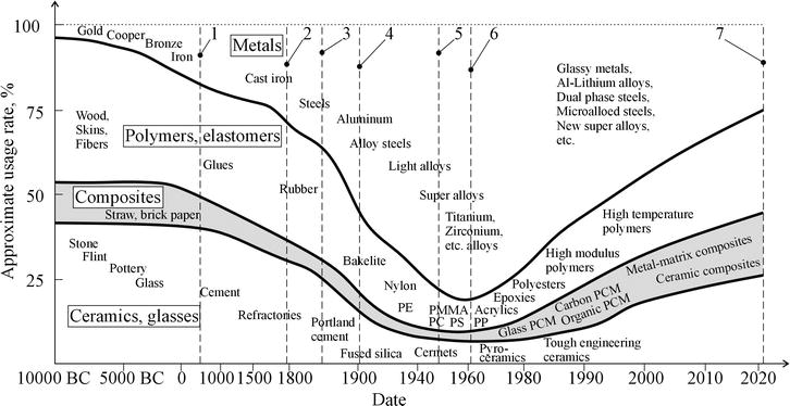
The development of new technologies and structural materials has been and still is directly related to the progress of civilization (see Figure 1) [1, 2]. Quantitative and qualitative progress in the development of our civilization has been made possible by the use of new materials. The aviation industry is a particularly clear demonstration of this thesis. Aerospace is a universally recognized indicator of progress in the development of advanced fields of knowledge. Historically, a great number of the achievements of civilization in science, engineering, and materials science have been closely tied to aviation [1, 2, 3].
Figure 1.
Developing and evolving structural materials over time [1, 2] (the time scale is nonlinear, graphs drawn on the base of different statistical data). 1: in 559 AD, several prisoners of emperor Wenxuan of Northern Qi, including Yuan Huangtou of Ye, were reportedly forced to fly a kite off a tower as an experiment. 2: the first manned flight, Montgolfier, went aloft in a tethered Montgolfier hot air balloon in 1783. 3: the first manned glider flight was made by a boy in an uncontrolled glider launched by George Cayley in 1853. 4: the first controlled, sustained flight in a powered airplane was made by brothers Wright in 1903. 5: the first documented supersonic flight was by Chuck Yeager in Bell X-1 in 1947. 6: the first piloted orbital flight was made by Yuri Gagarin in the rocket Vostok in 1961. The first manned hypersonic flight was made in 1961 by Robert white in the X-15 research aircraft at speeds in excess of Mach 6. 7: the first powered, controlled takeoff and landing on another planet or celestial body was the NASA rotorcraft ingenuity on Mars in 2021.
Up to now, aluminum and its alloys have been the main structural material used in aviation. The combination of strength, lightness, and low cost has made it indispensable in aircraft design [1, 4, 5].
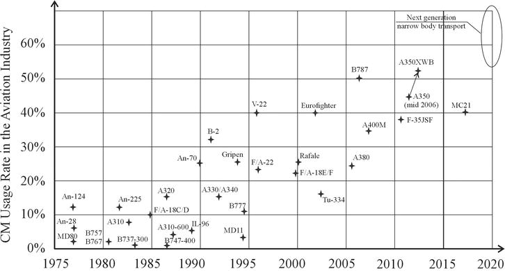
However, progress does not stand still. The ever-increasing demands on aerospace from military and civilian customers have led to a number of processes, one of which has been the search for new structural materials for aerospace industry. In the sixties of the twentieth century, looking for ways to lighten the structure, designers began to use composite materials (CM) everywhere (Figure 2), along with new metal alloys [1, 2, 5, 6, 7].
Figure 2.
CM usage rate in the aviation industry [6].
Polymer composites are widely used in the aerospace industry. Their composition and manufacturing technology are relatively simple. A woven base in the form of a fabric made of carbon fibers (or other fiber types) is impregnated with polymeric synthetic resins. The raw product is then pressed into the desired shape and applied heat. After the resin has cured, the edges of the product are treated. The product is then typically finished [5, 6].
Composites were first used in aviation in the form of phenol-impregnated modified wood. This material was then replaced by more advanced metal alloys. However, CM returned to aircraft structure when it became necessary to provide radio transparency in the radar antenna zone. Fiberglass composites perfectly met the radio transparency requirements and provided the necessary strength and stiffness as well as aerodynamic perfection for radar fairings [8].
In 1938, the Douglas Aircraft Company used fiberglass for the fairings of the Douglas A-20 Havoc bomber [8]. In 1964, the first all-fiberglass airframe, the H-301 Libelle (“Dragonfly”), received German and U.S.-type certification [8].
After the 1950s, aerospace engineers began to actively develop and introduce new CM reinforced with boron, carbon, and synthetic fibers into aircraft structures [1, 7, 9].
Boeing 727 (1963) was the first medium-range narrow-body airliner developed by the Boeing Corporation to use composite materials in its design. Carbon-epoxy rudder skins were made using CM. A 26% weight reduction of the rudder was achieved [9].
In 1967, the four-seat civilian piston-powered aircraft Eagle, built by Windecker, made its maiden flight in mostly composite [8].
Lockheed L-1011-1 Tristar made its first flight in 1970. Its design used carbon-epoxy aileron skins and later a carbon-epoxy keel. Further models of this aircraft increased the amount of CM. For example, in the Lockheed L-1011-500 Tristar (1978), Kevlar wing-to-fuselage fillets, fixed nose and trailing edge wing panels, trailing edge elevator and rudder panels, wing high-lift fairings, and fuselage fillets with the central engine were used. The weight reduction for CM units was 25% [9].
The design of DC-10 (1970) is generally similar to that of the Lockheed L-1011-1 Tristar. CM were used to make carbon epoxy skins and the rudder structural frame (30% weight reduction compared to metal structure) [9].
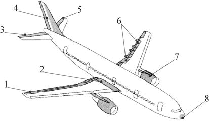
Airbus A310 (1982) used a carbon fiber-reinforced plastic vertical stabilizer, control surfaces, high-lift devices, and carbon fiber-based CM brakes (Figure 3). The total composite content in the A-310 design was 5% of the aircraft weight [9].
Figure 3.
Composite materials application in Airbus A310 [9, 10]. 1: ailerons; 2: wing-to-fuselage fillets; 3: elevators; 4: rudder; 5: fin; 6: high-lift devices and their fairings; 7: engine case parts; 8: radom.
ATR-42 (1984) and its extended version, ATR-72 (1989), have wing torsion boxes made entirely of carbon fiber (for the first time in passenger aviation). In general, the proportion of CM in the aircraft was 22.6%. Beech Model 2000 Starship 1 (1986) has wings and fuselage made of CM [8, 9].
Antonov Company (USSR-Ukraine) has a long history of CM application. The share of CM use in Antonov aircraft structures is increasing from 1 to 2% of the airframe weight in An-26 (1969) to 20% in An-70 (1994). Almost all wing high-lift devices were made of CM [9].
The appearance in 2005 of Hawker 4000 (Beechcraft, USA) and European A-380 with an all-composite fuselage brought the percentage of CM in the structure to 25–30% [8, 9].
The development of B787 (2009) and A350 (2013), whose wings and fuselage are mainly made of CM, brought this ratio to 50–55% [1, 4, 9]. Currently, Airbus and Boeing are the undisputed leaders in the use of CM structures in transport category aircraft.
There are also projects to upgrade existing aircraft. The main idea of such upgrading is to replace traditional metal structural materials with composite materials. For example, the Yakovlev Yak-40 upgrade project. CTP-40DT (2016) is a new variant of Yak-40. The wing of this aircraft is completely made of CM [11].
CM are very practical for the UAV industry. Such types of flying vehicles are especially sensitive to their weight. In the past, when structural materials were mainly metals, UAVs had poor flight performance and low applicability. Now, new generation of propulsions and structural materials based on CM use provide high flight performance of UAVs and their wide applications [2, 5, 7, 12, 13, 14].
Based on all the above, it can be concluded that the use of composite materials in the design of modern aircraft is reasonable. It is the CM that allow to achieve high weight efficiency for aircraft of the transport category.
The wing is one of the main units of a modern airplane, its main function being to generate lift [1, 4]. However, the wing (as well as the fuselage) is the largest unit of an airplane airframe. This is the cause of high aerodynamic drag. Thus, there is a contradiction: on the one hand, to increase the transport efficiency of the aircraft, the wing area should be increased. On the other hand, an increase in the wing area leads to an increase in its weight, aerodynamic drag, the loads acting on it, etc. [4].
The weight of a passenger aircraft wing is approximately 8–12% of the aircraft structural weight and 30–40% of the airframe weight [4, 15, 16, 17]. Up to 30–40% of the structural weight is the weight of the skin. One of the ways to reduce the weight of the wing, which depends on the designer, is the widespread use of composite materials for its elements.
The aerodynamic drag of a wing can be up to 60% of the total drag of an aircraft [4, 15, 18]. This is due to many aspects such as profile drag, friction, and induced drag. In this case, the induced drag is about 30% of the total drag of the aircraft [15, 18] or about 50% of the wing drag. The specificity of the induced drag is that it is directly related to the level of the lift force of the wing [4]. Thus, higher lift force results in higher induced drag.
There are several ways to reduce induced drag for a given lift [4, 11, 15, 16, 17]. So far, the most effective way to reduce induced drag is to increase its aspect ratio. For example, the Boeing company used folding wingtips on the new B777X, which allowed the wing aspect ratio to be increased by up to 10 [16, 17] (Figure 4). Another example is the new UAC MС-21. This aircraft has an aspect ratio of 11 [17]. In both cases, such a high aspect ratio was achieved by using CM.
Figure 4.
Deflectable wingtips of Boeing 777X [16].
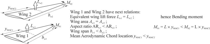
One of the consequences of a high aspect ratio is an increase in the bending moment in the wing (for the same lift force) (see Figure 5). The increase in internal wing loads leads to an increase in the stresses acting in the wing elements. Therefore, the longer the span of the wing, the more difficult it is to ensure its strength and stiffness. In other words, the increase in mass to provide strength can easily offset any positive effect of using a wing with a large aspect ratio. In addition to bending stiffness, torsional stiffness must also be considered. Torsional stiffness also decreases with increasing wing span.
Figure 5.
Equivalent lift force arrangement and bending moment evaluation [1].
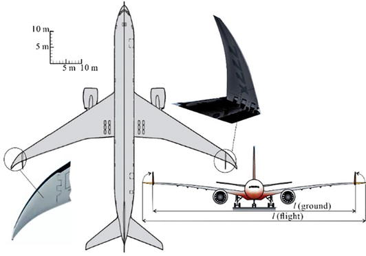
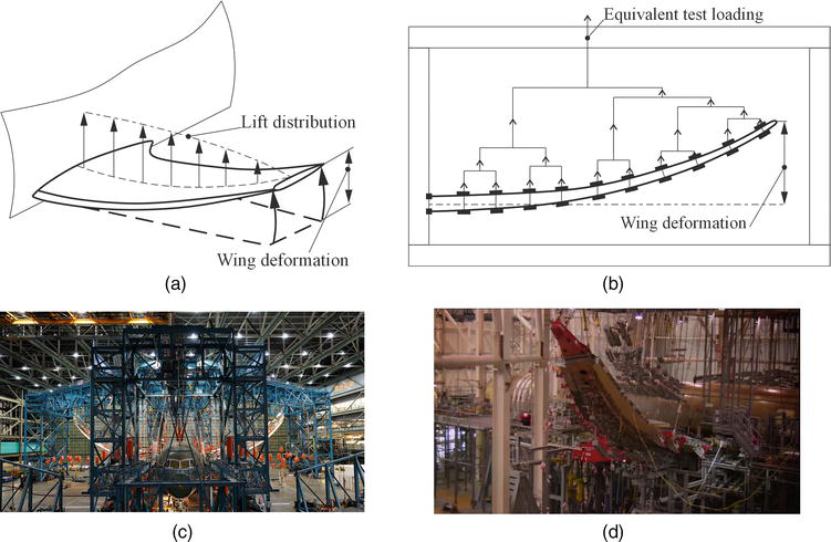
In this case, the positive property of composite materials, namely, high elasticity, was in full demand. Elasticity is the ability of a material to change its shape under load and return to its original shape when the load is removed. For example, the wing of B787 can bend up to seven meters (Figure 6c) [19], and also, the wing of A350XWB can bend up to five meters (Figure 6d) [20]. So, where aluminum loses strength and fractures, composites change shape only temporarily, bending under load without breaking.
Figure 6.
Wings flex tests. (a) Wing bending scheme in a flight; (b) scheme of the wing bending test; (c) Boeing B787 [19]; (d) Airbus A350XWB [20].
Another component of the drag of the wing is the joints of the structural elements of the wing that extend into the airflow. The share of such a drag reaches 3% [4, 16, 18, 21]. The use of CM reduces the number of joints that extend into the airflow due to the wide use of bonded and solid-state structures.
Thus, the use of composites in the wing structure has a significant positive effect on the main performance indicators of the wing. Namely, it allows to reduce the weight of the wing, reduce its drag by several factors at once, and increase the strength of the wing.
3. Composite materials and their performance for aircraft structure
The properties of composite materials depend on the composition of the components, their quantitative ratio, and the strength of the bond between them. By combining the volume content of the components, it is possible to obtain materials with the required values of strength, heat resistance, modulus of elasticity, or compositions with the required special properties, such as high tensile strength, high torsional stiffness, magnetism, and others, depending on the purpose.
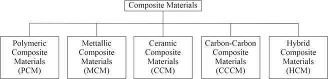
Figure 7 shows a brief classification of CM by the matrix material type.
Figure 7.
Brief classification of CM by the matrix material type [6].
Some terms are briefly described in Section 3.5.
3.1 Polymer composite materials
A large group of composites are polymer composite materials (PCM)—composites in which polymer material serves as a matrix. Their use has a significant economic impact.
Parts can be made from PCM using both processes typical of molded polymer products (injection molding, pressing, etc.) and special processes unique to this class of materials (winding, etc.).
3.1.1 Fiberglass
Fiberglass is a PCM reinforced with glass fibers formed from molten inorganic glass. Thermosetting resins such as polyester, phenolic, epoxy, and others and thermoplastic polymers such as polyamides, polyethylene, polystyrene, and the like are often used as the matrix.
Fiberglass materials have high strength, low thermal conductivity, and high electrical insulation properties and are transparent to radio waves.
Fiberglass is a low-cost polymer composite. Its use is justified in serial and mass production, aerospace industry, shipbuilding, radio electronics, construction, and automotive and railway engineering [2, 5, 6, 7, 10].
3.1.2 Carbon fiber-reinforced plastic
Carbon fiber-reinforced plastics are composite materials consisting of a polymer matrix and reinforcing elements in the form of carbon fibers. Carbon fibers are obtained from synthetic and natural fibers based on copolymers of acrylonitrile, cellulose, and others.
For the production of carbon fiber composites, the same matrices are used for fiberglass—thermosetting and thermoplastic polymers.
The main advantages of carbon fiber composites over glass fiber composites are their low density and higher modulus of elasticity. Carbon fiber-reinforced plastic is a very light and strong material. Carbon fibers, and therefore carbon plastics, have virtually no linear expansion.
Carbon plastics are used in aerospace industry, mechanical engineering, medicine, and sports equipment. Carbon plastics are used to produce high-temperature components for rockets and high-speed aircraft, brake pads and disks for aircraft and reusable spacecraft, and electrothermal equipment [2, 5, 6, 7, 10].
3.1.3 Boron fiber-reinforced plastic
Boron fiber-reinforced plastics are compositions consisting of a polymer matrix and boron fibers. Modified epoxy and polyamide binders are used to make boron plastics. The fibers can be either monofilaments, tapes braided with auxiliary glass filaments, or tapes in which boron filaments are interwoven with other filaments.
Due to the high hardness of the fibers, the material has high mechanical properties, and boron also serves to absorb thermal neutrons.
Boron fiber has high compressive strength, shear strength, hardness, and thermal and electrical conductivity. However, the high brittleness of the material makes it difficult to process and limits the shape of boron plastic products.
Composites based on boron fibers are mainly used in the aerospace industry to produce parts that are subjected to long-term stress [2, 5, 6, 7, 10]. The cost of boron fibers is very high due to the peculiarities of their production technology.
3.1.4 Organic fiber-reinforced plastic
Organic fiber-reinforced plastics are composites of polymeric binders and fillers, which are organic synthetic, less often natural, and artificial fibers in the form of tapes, yarns, fabrics, paper, and others.
In thermosetting organic plastics, the matrix usually consists of epoxy, polyester, and phenolic resins, as well as polyimides. The material contains 40–70% filler. The filler content in organic plastics is based on thermoplastic polymers—polyethylene, PVC, polyurethane, and others—from 2 to 70%.
The degree of orientation of filler macromolecules plays an important role in improving the mechanical properties of organic plastics. Macromolecules of rigid chain polymer (Kevlar) are mainly oriented along the fiber axis and therefore have high tensile strength along the fibers. Body armor is made of Kevlar-reinforced materials. Organic plastics have low density, are lighter than glass and carbon fiber-reinforced composites, have relatively high tensile strength and impact strength but low compressive and flexural strength.
Organic plastics are widely used in automotive, aerospace, radio electronics, shipbuilding, chemical engineering, production of sports equipment, and others [2, 5, 6, 7, 10].
3.2 Metal matrix composites
Aluminum, magnesium, nickel, copper, and other metals are used to make metal matrix composites (MMC). Fillers are high-strength fibers and refractory particles of varying dispersity that are not dissolved in the base metal.
The properties of dispersion-hardened metal composites are isotropic, that is, the same in all directions. An addition of 5–10% of reinforcing fillers (such as refractory oxides, nitrides, borides, and carbides) leads to increased resistance of the matrix to loading and increased heat resistance of the composite in comparison with the original matrix.
Reinforcing metals with fibers, filamentary crystals, or wires significantly increases both the strength and heat resistance of the metal. For example, aluminum alloys reinforced with boron fibers can be operated at temperatures up to +450–500°C instead of +250–300°C [2, 5, 6, 7, 10].
Oxide, boride, carbide, nitride metal fillers, and carbon fibers are used. Ceramic and oxide fibers, due to their brittleness, do not allow plastic deformation of the material, which causes significant difficulties in the manufacture of products, while the use of more plastic metal fillers allows deformation.
Such composites are obtained by impregnating fiber bundles with metal melts, electrodeposition, mixing metal with powder and subsequent sintering, etc. Fiber-reinforced metals are used in aerospace and other industries.
3.3 Ceramic matrix composites
Ceramic composite materials (CCM) are materials in which the matrix is ceramic, and the reinforcement is metallic or nonmetallic fillers.
Reinforcing ceramic materials with fibers and dispersed metal and ceramic particles results in high-strength composites.
The range of fibers suitable for reinforcement is limited by the properties of the base material. Metal fibers are often used. The tensile strength does not increase much, but the thermal resistance increases—the material breaks less when heated, but there are cases where the strength of the material decreases. This depends on the ratio of the thermal expansion coefficients of the matrix and the reinforcing fiber. Ceramic composites with carbon fibers are promising for high-temperature applications.
The applications for composite materials are numerous [2, 5, 7, 8, 10, 12, 13, 14, 22]. In addition to the aerospace, space, and other specialized industries, they are in demand in the construction of power turbines, the automotive industry, mining, metallurgy, construction, etc. The range of applications of these materials is constantly expanding.
3.4 Properties of composite materials
As mentioned above, the main advantages of composite materials are their high specific and fatigue strength, high wear resistance, and stiffness. As the matrix of the composite is responsible for the uniformity of the material, its resistance to external influences, and the distribution and transfer of stresses, the reinforcing material acts as a reinforcing structure and is a stronger component than the matrix. By selecting the properties of the matrix and the reinforcing material, it is possible to achieve the required combination of manufacturing and operational properties. Some performances of different CM are shown in Table 1 [2, 6, 7, 10, 22].
No.
Matrix material
Reinforcing material
Density, kg/m3
Tension stress, MPa
Elasticity modulus, GPa
1
Epoxy
Glass fibers
1900–2200
1200–2500
50–68
2
Organic fibers
1300–1400
1700–2500
75–90
3
Carbon fibers
1400–1500
800–1500
120–220
4
Boron fibers
2000–2100
1000–1700
220
5
Aluminum
Carbon fibers
2300
800–1000
200–220
6
Boron fibers
2600
1000–1500
220–250
7
Magnesium
Carbon fibers
1800
600–800
180–220
8
Boron fibers
2000
700–1000
200–220
9
Nickel
Tungsten wire
12,500
800
265
10
Molybdenum wire
9300
700
235
11
Carbon
Carbon fiber
1500–1800
350–1000
120–220
12
Ceramic
Silicon carbide fiber
3200
480
—
Table 1.
Basic CM properties for different matrix and fiber materials.
As shown in Table 1, there is a wide range of available properties for CM based on different components. This makes it possible to use CM for different operational conditions (highly stressed elements, thermally stressed elements, radio-transparent elements, etc.) for aircraft structures.
3.5 Brief glossary
Acrylonitrile is an organic compound with the chemical formula CH2CHCN and the structure H2C〓CH▬C☰N.
Aramid is any of the number of synthetic polymers (substances composed of long-chain, multiunit molecules) in which repeating units containing large phenyl rings are linked together by amide groups.
Biopolymers are natural polymers produced by the cells of living organisms.
Cellulose is an organic compound with the chemical formula (C6H10O5)n and the most abundant biopolymer on the Earth.
Electrodeposition is a process of producing a metal coating on a solid substrate through the reduction of cations of that metal by means of a direct electric current.
Epoxy resin is a type of polymer that is made up of a combination of epoxide groups and other molecules.
Ethylene is a hydrocarbon which has the chemical formula C2H4 or H2C〓CH2.
Filamentous crystals are single crystals in the form of needles and fibers with diameters ranging from a few nanometers to hundreds of microns and a large length-to-diameter ratio (typically 100–1000).
Kevlar (para-aramid) is a strong, heat-resistant synthetic fiber, related to other aramids such as Nomex and Technora.
Monofilament is a single filament of the synthetic fiber.
Monomer styrene is an organic compound with the chemical formula C6H5CH〓CH2.
Nomex is a flame-resistant meta-aramid material.
Para-aramid is an aromatic polyamide that is characterized by long rigid crystalline polymer chains.
Phenol (also known as carbolic acid or phenolic acid) is an aromatic organic compound with the molecular formula C6H5OH.
Phenolic resins are synthetic polymers made by reacting phenol (or substituted phenols) with formaldehyde.
Polyamide is a polymer that comprises repeated units linked together by amide bonds.
Polyester resins are synthetic resins formed by the reaction of dibasic organic acids and polyhydric alcohols.
Polyethylene is a thermoplastic that also happens to be the most common plastic. It is produced through the use of special catalysts that affect polyolefins at moderate temperature and pressure.
Polyimide is a polymer containing imide groups belonging to the class of high-performance plastics.
Polyolefins are produced by polymerizing, respectively, ethylene and propylene, mainly obtained from oil and natural gas.
Polystyrene is a polymer made from the monomer styrene, a liquid hydrocarbon that is commercially manufactured from petroleum.
Polyurethane is an ultralight, bearing, elastic, impact-resistant, sound-insulating compound.
Polyvinyl chloride (PVC or vinyl) is an economical and versatile thermoplastic polymer.
Propylene is a gaseous hydrocarbon with the chemical formula C3H6, obtained from petroleum.
Technora is an aromatic copolyamide that has a highly oriented molecular structure, consisting of both para and meta linkages.
Thermoplastic (thermosetting resins) is a type of polymer that liquifies upon heating and cannot be reused after cooling.
4.1 Methods for assessing the strength of composite materials
The fracture mechanics of CM units is very complex. There are many approaches to assess their strength based on different fracture criteria [23, 24, 25]. They are usually based on experimental results from their tensile, compression, and shear tests. The fracture criterion defines the critical combination of operational stresses (deformations) that will lead to failure.
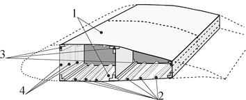
First, it is necessary to make a conditional partition of the unit into simplified components. For example, for a wing, at least two structural components can be conditionally identified: a panel with stiffeners (skin with stringers) and a spar (Figure 8).
Figure 8.
Wing subparts. 1: upper and lower panels; 2: stiffeners of panels; 3: spars; 4: stiffeners of spars.
For aircraft of the transport category, the intensity of wing loading requires to select the torsion-box load-carrying structure for their wings [4, 26, 27]. The main feature of this type of load-carrying structure is that most of the bending moment is supported by the wing panel. The lift force acts as a shear force into the spar web. So, both of these structural components can be considered as the panel with complex loading configuration. Both these panels have stiffeners: it is a set of stringers for skin and a set of struts for spar web. Caps of a spar can be considered as stiffeners of skin panels. These structural components can also be simplified to a composite package [27].
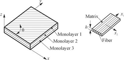
In the general case, the strength analysis of a composite package is reduced for the determination of the stress-strain state of its layers and the calculation of their safety factors according to one or another criterion [27, 28]. The minimum of these factors determines the safety margin of the CM package as a whole. Figure 9 shows a typical CM package structure. In the following, the most common fracture criteria used in the practice of composite strength analysis are briefly summarized.
Figure 9.
A typical CM package structure.
Maximum stress criterion: according to this criterion, monolayer failure occurs when the following conditions are met:
A=maxσ1XTσ1XCσ2YTσ2YCτ12S12≥1.E1
The safety factor is the result of the following equation η = A−1.
Here, A is the cross-sectional area; σ1, σ2, and τ12 are the stresses acting in the monolayer; XT, XC, YT, YC, and S12 are the failure stresses.
This criterion has the following disadvantages. In general, the matrix is in a three-dimensional stress state, but even for relatively thin plates where σ3 = 0 and transverse shear strains can be neglected, there is no mutual influence of the components of the plane-stress state on the strength of the matrix, which may lead to overestimation of the matrix strength under a combination of loads.
Tsai-Hill criterion: a quadratic criterion based on the fourth (energy) theory of strength. Monolayer failure occurs when the condition is satisfied:
A=σ12X2−σ1σ2X2+σ22Y2+τ122S122≥1.E2
The safety factor here is calculated by the equation η=A−1.
The main disadvantage of this criterion is that it is impossible to determine the cause of monolayer failure: matrix or fiber failure has occurred. In addition, the criterion does not distinguish between stress combinations σ1 and σ2, as biaxial tension or biaxial compression are equivalent in this case.
Hofmann criterion: this criterion is based on the sum of the linear and quadratic stress invariants. Monolayer failure occurs when the following condition is satisfied:
The safety factor is determined by solving the quadratic equation η2 + bη – 1 = 0.
The criterion distinguishes between combinations of stresses σ1 and σ2 due to additional linear terms compared to Hill’s criterion. As with Hill’s criterion, it is rather problematic to determine the cause of failure.
Tsai-Wu criterion: it is a variation of the Hofmann criterion. Monolayer destruction occurs when the following condition is satisfied:
This criterion differs from the Hofmann criterion by the factor used for σ1 and σ2. In general, the factor F12 can be in the range −1.0 ≤ F12 ≤ 1.0.
A characteristic feature of the criteria discussed above is their uncertainty with respect to what happened in the monolayer—whether the matrix or the fiber was destroyed. At the same time, this is very important when analyzing the strength of a composite package. Therefore, criteria that analyze the strength margins of both the matrix and the fiber separately are becoming more common.
Hashin-Rotem criterion: this criterion assesses fiber and matrix strength separately.
The following relationships are used to determine the fiber strength:
σ1XT2+τ12S122=1forσ1>0,σ1XC2=1forσ1<0.E5
The strength of the matrix is determined by the following relations:
The conditions for interlayer delamination are specified by the relation:
σ3ZT2+τ23S232+τ31S312=1.E7
The criteria considered above belong to the group of criteria based on the ultimate stresses of the monolayer. In addition, there are a number of criteria based on the ultimate strain of the monolayer.
The maximum strain criterion is one of the most common criteria. According to this criterion, monolayer failure occurs when the following conditions are met:
A=maxε1ε1Tε1ε1Cε2ε2Tε2ε2Cε12γ12≥1.E8
The safety factor is calculated using the following equation η = A−1.
Here, ε1, ε2, and ε12 are the strains of the monolayer; ε1T, ε1C, ε2T, ε2C, and γ12 are the strains and their failure in tension, compression, and shear. Formally, this criterion is the same as the maximum stress criterion. The difference between them is that the elastic characteristics of the matrix can have a nonlinear behavior, and the strain criteria make it possible to take this factor into account to a certain extent.
There are other criteria with different approaches to taking into account stresses and strains. Here, the more commonly used one has been explained.
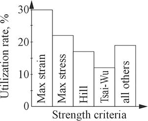
Figure 10 illustrates the extent to which certain strength criteria are used in practice.
Figure 10.
Application of various failure criteria to analyze the strength of composite units [28].
4.2 Strength and stability analysis of CM panels with stiffeners
Depending on the stiffness ratio of skin and stiffeners, the reinforced CM plates can be considered as composite plate sets connected along nodal lines or as structurally orthotropic sets with given stiffness characteristics. Depending on the model adopted, different numerical approaches are also used for the strength analysis.
The study with discrete models allows detection, in addition to the general instability, of some local forms of loss of stability. However, to fully study the behavior of the panel after a local loss of stability, a discrete model should be used in combination with geometric and physical nonlinearities.
Therefore, when solving the problem in a nonlinear form, the nonlinear stress-strain behavior should be analyzed at each step according to the strength criteria in order to determine the possible failure of the plate before a general form of loss of stability occurs. This type of failure is called crippling strength in the reference literature.
In addition to the abovementioned complex way of studying the behavior of a reinforced panel based on a discrete model in a geometric nonlinear form, it is possible to use a model of a structurally orthotropic plate as a substitute for a real reinforced panel. In this case, the problem is reduced to the calculation of the “smeared-out” stiffness parameters of such an orthotropic plate.
4.2.1 Numerical-analytical method for calculation of the overall stability of CM panels, taking into account the local loss of skin stability
The solution of the general stability problem of a reinforced CM panel is reduced to the solution of the stability problem of an anisotropic (orthotropic) plate based on the equation:
Here, w is the lateral deflection; Dx, Dy, and Dxy are the stiffnesses along their respective axes; Nx, Ny, and Nxy are the forces in their mid-plane.
The critical compressive forces can be approximated by the following equations:
A rectangular plate hinged along the contour, loaded at the edges x = 0 and x = a by the compressive forces Nxo:
Nxcr=2π2b2DxDy+μxyDx+2Dxy.E10
Rectangular elongated plate fixed on all edges:
Nxcr=2π2b24.6DxDy+2.67μxyDx+5.33Dxy.E11
Rectangular elongated plate, one unloaded edge is free and the other three are hinged (a/b > 4):
Nxcr=12Dxyb2+π2Dxa2.E12
Rectangular plate (1 < a/b < ∞) whose loaded edges are hinged and whose unloaded edges are fixed:
Nxcr=π2b2Dxm2ba2+2.67μxyDx+5.33Dyab2+1m2+Dxy.E13
In the practice of studying the stability of reinforced metal panels and shells, the concept of a “framed” shell or panel has developed. This means that the main material is concentrated in the reinforcements and the skin is comparatively thin. The same assumption applies to CM panels. The comparatively early local loss of stability of the skin and the reduction of its performance in the subcritical area are accounted for by the reduction factor method.
The assumption that the shell or panel is “framed” leads to the assumption that there is no local loss of stability of the reinforcement elements. As a result, the considered approach does not take into account the possibility of failure of the reinforcement after local loss of stability.
For a reinforced plate considered as an orthotropic plate, the following relations are valid:
N=Bε,M=DχB=Bij=BTD=Dij=DTij=123,E14
for B13=B23=D13=D23=0, and N=NxNyNxyT and M=MxMyMxyT are forces and moments in the panel; ε=εxεyγxyT and χ=χxχyχxyT are strains and curvatures at the reference plane.
If the skin is regularly supported by longitudinal and lateral stiffeners installed with pitches bc and bf, respectively, the “smeared-out” stiffness parameters of the supported panel are calculated using the following equations:
Here, rts=ExEs1−μxyμyx and rtf=EyEf1−μxyμyx; Es, Ef, Gs, and Gf are the elastic and shear moduli of the longitudinal and lateral reinforcement; Fs, Ff, Is, If, IsP, and IfPare the areas, eigencentral, and polar moments of inertia for the longitudinal and lateral reinforcement sections, respectively; zs and zf are the distances from the centers of gravity of the longitudinal and lateral reinforcement sections to the midplane of the skin; Gsfhsf is the shear stiffness of the reinforcement set without skin, which is related to the way the longitudinal and lateral reinforcements are attached to each other.
The given equations for the secant and tangent stiffness parameters are further used in the calculation of the precritical stress-strain behavior and the overall stability of the reinforced panel. In the particular case of no skin buckling, these equations are transformed into the usual equations for the stiffness parameters of the reinforced panel.
4.2.2 Methodology for calculating the structural capacity of panels using FEM
The analysis of the structural capacity of reinforced panels based on FEM requires special approaches compared to, for example, the analysis of smooth plates. The solution of such problems requires a certain experience in their simulation and in analyzing the obtained data. Some peculiarities and tips for solving the problems of assessing the structural capacity of reinforced panels are presented below.
The analysis of panels operating in tension does not cause significant difficulties in assessing their strength. The main difficulties lie in the analysis of the panel operating in compression or under the action of a combination of loads and are related to the issues of its local and overall stability. A peculiarity of reinforced thin-walled structures, which include stiffened panels, is that they can have local forms of stability loss related to the loss of stability of the skin and elements of the reinforcement set. This does not exhaust the structural capacity of the panel, but only reduces its stiffness characteristics. Panel failure occurs either when the load reaches the value of its total loss of stability or when the strength of its separate elements is exhausted.
For metal panels, a natural limitation on the level of development of subcritical strains is the requirements of aviation regulations for the absence of residual strains in the structure under operational loads.
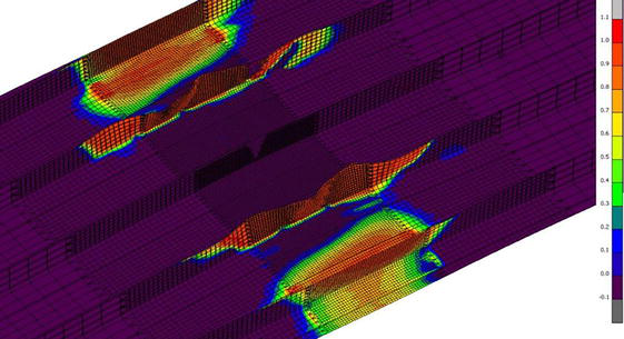
For panels made of CM, these requirements are transformed into requirements of no violation of composite continuity under these loads, that is, no matrix failure or delamination in it. For panels with a comparatively weak set of stiffeners, in addition to the loss of stability of the skin, there may be a local loss of stability of the stiffener elements: their webs or caps, while the stiffener itself remains in the plane of the panel. This phenomenon is known as panel creep and must be taken into account when assessing the structural capacity of the panel. Panel creep can be related not only to the local loss of stability of the stiffener, but also to its deformation interaction with the skin that has lost stability (Figure 11).
Figure 11.
Deformation interaction of the skin with the set of stiffeners [29].
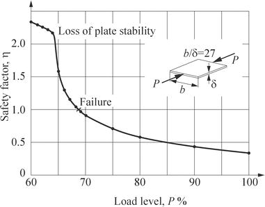
In composites, creep can quickly lead to stiffener failure. This depends mainly on the specific thickness of the stiffeners, that is, the ratio of wall or cap width to thickness. The higher the ratio, the faster the creep failure. As an example, Figure 12 shows a graph of the change in the safety factor of a plate made of CM with a ratio of b/δ = 27 during its subcritical deformation. It can be seen that, after the loss of plate stability, its failure occurs in the 5% range of load increase, and the safety factor accordingly decreases more than twice.
Figure 12.
CM plate safety factor changes after the loss of stability [28].
The finite element model of a panel is created based on its geometric data. Typically, this is a bend-diaphragm element. In terms of length, it is desirable to consider three-span panels. This reduces the influence of boundary conditions at the panel edges on the solution results and forms natural boundary conditions for the offset part of the model, that is, the middle span. The lateral dimensions of the model are usually chosen based on the wide panel concept, when there are no natural boundary conditions at the longitudinal edges due to the operation of the panel as part of the structure. The wide panel concept assumes that the boundary conditions at its longitudinal edges have minimal influence on the solution. Typically, five to six stiffeners in the model are sufficient to satisfy these conditions using finite elements.
Plate edge torsion should be locked when a fixed state is formed. Lateral movement of the edges should not be restrained. This causes biaxial compression of the skin in the edge zone when the plate is loaded, resulting in an earlier loss of stability. Forming hinge support conditions does not require any additional conditions on the displacements of the edges, except for limiting their displacements out of the panel plane.
The panel loading is provided by setting distributed loads on its edges. The values of these loads are set in proportion to the longitudinal stiffnesses of the panel elements. This results in its central loading.
The size of the computational mesh of the model is mainly determined by the parameters of the panel and the objectives of the analysis. If it is known that there will be no local forms of stability loss, the nodal mesh can be less detailed.
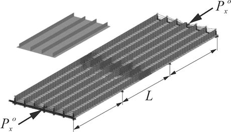
A typical example of such a model of a panel with stiffeners is shown in Figure 13.
Figure 13.
Typical reinforced panel model for analysis [29].
The application of the nonlinear form of FEM to the analysis of the stability of thin-walled units opens much wider possibilities for a complete analysis of the structural capacity of units. This is mainly due to the possibility of considering the subcritical behavior of a unit and the possibility of monitoring its strength by some or other failure criteria at each stage of its loading. However, there are serious difficulties in the practical use of this approach. First of all, it takes a lot of time to analyze such problems.
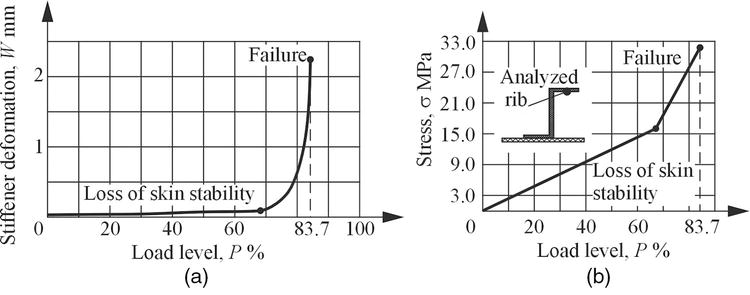
The results of the analysis of the reinforced panel show the deformation of the stiffeners from the plane of the panel and the growth of the stresses in the stiffener as a function of the percentage of the load are observed. The intensive growth of the stiffener deformation indicates that the point of total loss of stability of the panel is near, and the analysis of its stress-strain behavior allows to specify the failure load. Figure 14 shows typical dependencies of stiffener deformation growth and stresses in its rib as a function of load.
Figure 14.
Graphs of the stringer deformation growth (a) and the stringer rib stress (b) as a function of the load [28, 30].
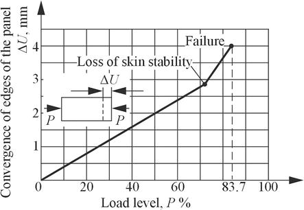
The prediction of the critical load can be based on the method of generalized tangential stiffness of the panel using. Conventionally, this stiffness can be defined as the ratio of the percentage of the load increment to the increment of the panel edges convergence value, T = ΔP/ΔU. As it is the tangential stiffness that determines the stability of the panel, if it decreases sharply, it can be concluded that the critical point of the total loss of panel stability is near. As an example, Figure 15 shows a typical graph of the convergence of the edges of one of the panels as a function of the percentage of the applied load.
Figure 15.
Graph of the dependence of the value of the panel edges convergence on the percentage of the applied load [28, 30].
Thus, in the area of 80% load, T = (87.5 − 75)/(3.97 − 3.148) = 15.2, and at the finish of the process, T = (88.67 − 88.65)/(4.133 − 4.088) = 0.44, that is, the tangential compressive stiffness of the panel decreased almost 35 times.
4.2.3 Assessment of panel structural strength
In the airframe structure, panels typically operate under combined loading conditions, the major components of which are axial and shear loads. The values of these loads depend on both the location of the panel in the structure and the design loading case. Therefore, it is convenient to assess the structural strength of panels using diagrams of their strength and general stability, plotted in the coordinates of the acting linear compressive and shear loads. The combination of these diagrams provides a visual illustration of the structural strength of the panel and the causes of its failure (Figure 15).
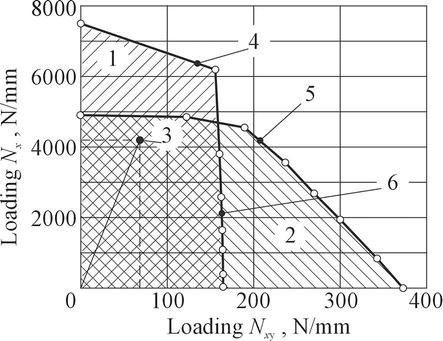
Presenting such diagrams for a number of typical panels of the considered structure and plotting on them the points of specific combinations of loads acting on the panel in various design cases, it is possible to evaluate its structural strength and available safety factor. At the preliminary stage of design, such diagrams can be drawn using numerical and analytical calculation methods. However, at the stage of detailed design and verification analysis, it is desirable to use nonlinear FEM for this purpose. This is especially true for CM panels. This is due to the fact that analytical calculation methods often do not take into account the effects of panel crippling. As an example, Figure 16 shows the diagram of the structural strength of a wing panel made of CM as plotted by the results of nonlinear FEM analysis.
Figure 16.
Diagram of the structural strength of a CM wing panel [28]. 1: zone of the overall instability; 2: zone no strength; 3: design load combinations; 4: limit of strength; 5: limit of stability; 6: limit of structural strength of the panel.
The diagram clearly shows that the structural strength of the panel is determined by its overall stability when the ratio of shear and compression loads ξ = Nxy/Nx < 0.32 and by the strength of the composite when ξ > 0.32. Having a point on the diagram that defines the combination of loads acting on the panel, it is easy to estimate the available reserves of its strength by drawing a ray through this point from the origin to its intersection with the boundary of the structural strength of the panel.
Modern level of material science allows to replace traditional metallic structural materials by new composite materials. This trend provides weight reduction of airframes. However, CM units require more complex approaches to the design, analysis, and verification processes.
There are several criteria to assess the strength of CM basic elements. The aircraft wing structure consists of complex units. For them, it is necessary to apply certain levels of approximation because the full process of strength assessment can take a long time.
The aircraft wing consists of two main structural components: skin and spar. Both can be considered as a reinforced panel. Such an approach allows to unify different analysis models for a relatively well-known model.
On the basis of these conditions, it is possible to assess the strength of the wing by criteria for a reinforced panel. Some peculiarities and recommendations for the selection of parameters of the model of such a panel have been given. Also, several cases have been explained and analyzed as examples.
References
1.Tiniakov D, Li L. Airworthiness Engineering Basis. Beijing: Beijing Press; 2020. 217 p. ISBN 9787512432093
2.Ashby M. Material Selection in Mechanical Design. Oxford: Butterworth-Heinemann; 2000. 534 p. ISBN 0750643579
3.Anderson JD. The Airplane, a History of its Technology. Reston, VA: American Institute of Aeronautics and Astronautics; 2002. 369 p. ISBN 1563475251
4.Torenbeek E. Advanced Aircraft Design: Conceptual Design, Analysis, and Optimization of Subsonic Civil Airplanes. Chichester, West Sussex: John Wiley and Sons.; 2013. DOI: 10.1002/9781118568101
6.Li L, Tiniakov D. Airworthiness Design of Composite Structures. Beijing: Beijing press; 2021. 220 p. ISBN 9787512435773
7.Baker A, Dutton S, Kelly D. Composite Materials for Aircraft Structures. Reston: AIAA Education Series.; 2004. 569 p. ISBN 1563475405
8.Feygenbaum Y, Butushin S, Bozhevalov D, Sokolov Y. Composite materials and history their introduction in aircraft structures. Scientific Bulletin of GA. 2015;7(318):24-37
9.Kiva D. Stages of formation and beginning of expand use of polymer composite materials in constructions of passenger and transport airplanes. Aerospace Technic and Technology. 2014;6:5-16
10.Gay D, Hoa SV, Tsai SW. Composite Materials: Design and Application. Boca Raton: CRC Press LLC; 2003. 523 p. ISBN 1587160846
11.Moksha O. SibNIA Completes Research on the CTP-40DT. [Internet]. Aeroo.ru Aviation News. 2019. Available from: https://aeroo.ru/30135-SibNIA-zavershil-raboty-po-samolietu-STR-40DT.html [Accessed: November 28, 2023]
12.Randall R, Solo L, Chen C. Unmanned Aerial Vehicle. Patent, China, ZL201621265147.4, 2017
13.Chen C, Bo L. Unmanned Aerial Vehicle. Patent, China, ZL201621265305.6, 2017
14.Randall R, Chen C. Aircraft and Aircraft Control System, USA, US 2019/0263513 Al, 2019
15.Kretov A, Tiniakov D. Evaluation of the Mass and Aerodynamic Efficiency of a High Aspect Ratio Wing for Prospective Passenger Aircraft, Aerospace. MDPI; 2022;9(9):497. DOI: 10.3390/aerospace9090497
16.Kretov A, Tiniakov D. Evaluation of wing structures at the conceptual stage of transport category aircraft projects. Aviation, Issue. 2022;26(4):235-243. DOI: 10.3846/aviation.2022.18041
17.Kretov AS, Tiniakov DV, Shataev PA. Conceptual assessment of the fuel efficiency of passenger aircraft with the transition to composite wings. Civil Aviation High Technologies;26(2):72-90. DOI: 10.26467/2079-0619-2023-26-2-72-90
18.Tinyakov DV. Analysis of geometric parameters features of the wings of modern transport category airplanes from the top-view. Open Information and Computer Integrated Technologies. 2013;62:14-20
19.McKeegan N. 787 Dreamliner completes wing-bending test. [Internet]. New Atlas. 2010. Available from: https://newatlas.com/787-dreamliner-completes-ultimate-load-test/14663/?0000016e-d4b4-d036-a77f-defe204f0000-page=2 [Accessed: November 28, 2023]
20.Turbli. How Much Can an Airplane Wing Bend? [Internet]. Turbli. 2022. Available from: https://turbli.com/blog/how-much-can-an-airplane-wing-bend/ [Accessed: November 28, 2023]
21.Brushgens GS. Aerodynamic and dynamic of long-haul aircraft. In: Proceedings of the TsAGI and Avia PRC, Moscow-Beijing. Moscow-Beijing: TsAGI and Avia PRC; 1995. p. 772. ISBN 7800467899
22.Trento C. Silicon Carbide Fibers Used in Composite Material Reinforcement [Internet]. Stanford Advanced Materials. 2022. Available from: https://www.samaterials.com/content/silicon-carbide-fibers-used-in-composite-material-reinforcement.html [Accessed: November 28, 2023]
23.Tsai SW, Wu EM. A general theory of strength for anisotropic material. Journal of Composite Materials. 1971;5:58-80
24.Hashin Z. Failure criteria for unidirectional fiber composites. Journal of Applied Mechanics. 1980;47(2):329-334. DOI: 10.1115/1.3153664
25.Puck A, Schurmann H. Failure analysis of FRP laminates by means of physically based phenomenological models. Composites Science and Technology. 1988;58:1045-1067. DOI: 10.1016/s0266-3538(96)00140-6
26.Tiniakov D, Li L, Su Y. Airworthiness Design of Civil Aircraft Systems and Structure. Beijing: Beijing Press; 2018. 366 p. ISBN 9787512427624
27.Karpov Y. Design of Parts and Units from Composites. Kharkov: KhAI; 2010. 767 p
28.Grishin V, Dzyuba A, Dudarkov Y. Strength and Stability of Elements and Joints in Composite Aircraft Structures. Moscow: TsAGI; 2013. p. 139. ISBN 9785940522287
29.Golovan V, Dudarkov Y, Levchenko E, Limonin M. Load bearing capacity of composite panels with in-service damages. Journal Trudy MAI. 2020;110:26. DOI: 10.34759/trd-2020-110-5
30.Dudarkov Y, Levchenko E, Limonin M, Shevchenko A. Computational studies of some types of operational and technological damages impact on bearing capacity of stringer panels made of composite fiber reinforced plastic. Journal Trudy MAI. 2019;106:24. DOI: 10.34759/trd-2020-110-5
Written By
Chunmei Chen, Ryan Randall and Dmytro Tiniakov
Submitted: 09 January 2024Reviewed: 11 January 2024Published: 21 February 2024