Open Access is an initiative that aims to make scientific research freely available to all. To date our community has made over 100 million downloads. It’s based on principles of collaboration, unobstructed discovery, and, most importantly, scientific progression. As PhD students, we found it difficult to access the research we needed, so we decided to create a new Open Access publisher that levels the playing field for scientists across the world. How? By making research easy to access, and puts the academic needs of the researchers before the business interests of publishers.
We are a community of more than 103,000 authors and editors from 3,291 institutions spanning 160 countries, including Nobel Prize winners and some of the world’s most-cited researchers. Publishing on IntechOpen allows authors to earn citations and find new collaborators, meaning more people see your work not only from your own field of study, but from other related fields too.
Ceramic-matrix composites (CMCs) are a class of materials that combine the high-temperature stability and strength of ceramics with the toughness and damage tolerance of fibers. One of the key advantages of CMCs is their ability to withstand high temperatures, making them ideal for applications in gas turbines, rocket nozzles, and heat exchangers. The high-temperature stability of CMCs is due to the ceramic-matrix material, which has a high melting point and excellent thermal conductivity. This allows CMCs to operate at temperatures above 1000°C, where traditional metal alloys would fail. These composites have gained significant attention in recent years due to their potential for use in a wide range of applications, including aerospace, automotive, energy, and defense. This chapter reviews the recent progress in the design, application, and challenges in CMCs, especially the hot-section components design and testing at elevated temperatures.
College of Civil Aviation, Nanjing University of Aeronautics and Astronautics, Nanjing, P.R. China
*Address all correspondence to: llb451@nuaa.edu.cn
1. Introduction
Ceramic-matrix composites (CMCs) with continuous fiber reinforcement possess high specific strength and modulus, and have already been recognized as attractive structural ceramic materials for gas turbine hot-section components in civil and military aero engines [1, 2]. The tensile curves of CMCs show obvious nonlinear behavior due to multiple damage mechanisms, e.g., matrix cracking, interface debonding, and fiber failure and pullout [3]. Compared to monolithic ceramics, CMCs can be used under high thermos-mechanical loads [4, 5, 6].
This chapter presented a review on the recent design, application, and challenge of CMCs in hot-section components in aero engines, e.g., combustor liners, turbine components, and exhaust components. These hot-section components were developed by France, United States, China, Japan, etc., and have already been applied in military or commercial aero engines.
2. Application of ceramic-matrix composites in aero engines
2.1 Application on combustor liner
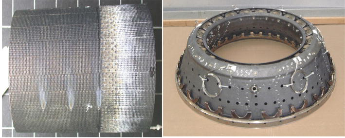
In the early 1980s, SNECMA company started research on the application of CMCs in hot-section components of aircraft engines. The CERASEPR series CMC materials were developed using chemical vapor infiltration (CVI) technology and tested on M88 engines. On this basis, SNECMA has upgraded and improved the CERASEPR series materials, as well as the high-temperature mechanical properties and temperature resistance of the materials. SNECMA company used improved materials to produce a full-size combustion chamber component [7], as shown in Figure 1. The CERASEP®-A410 afterburner flame holders were tested for 143 hours with a maximum temperature of 1180°C without any defect detected by nondestructive evaluation (NDE), and the CERASEP®-A415 combustor liner was tested for 180 hours (600 representative cycles) including 100 hours of maximum working conditions. The combustor linear with the CMC mixer was demonstrated on CFM56 engine. The weight gain of the CMC mixer was about 35%.
Figure 1.
CERASEP®A415 rig and inner & outer liners of an engine combustor [7].
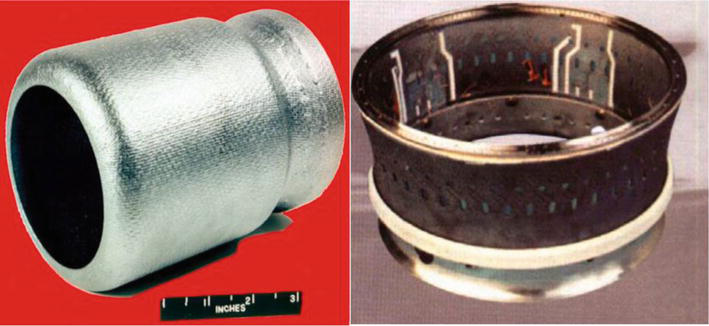
GE and Allison collaborated to develop and verify the CMC combustor liners on XTC76/3 and passed a 5000 hrs full life-cycle operation test and 500 h high-temperature operation test at 1200°C [8], as shown in Figure 2.
Figure 2.
CMC combustor liner by GE and Allison [8].
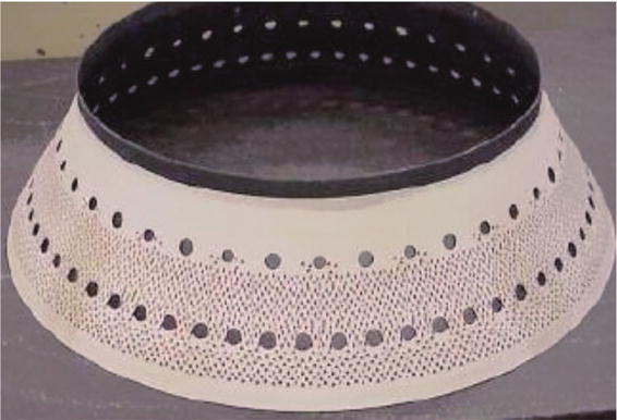
GE has manufactured and validated a SiC/SiC low-emission combustor liner with multiple inclined cooling hole [9], as shown in Figure 3. Experiments have shown that using this SiC/SiC combustor liner can reduce the cooling air of the combustor by 50%, reduce the mass by 50%, and reduce the NOx emissions by about 20%. The CMC inner and outer combustor liners, high-pressure turbine (HPT) stage 1 and stage 2 nozzles, and stage 1 shrouds were expanded to the GE9X aero engine.
Figure 3.
Low emission SiC/SiC combustor liner developed by GE company.
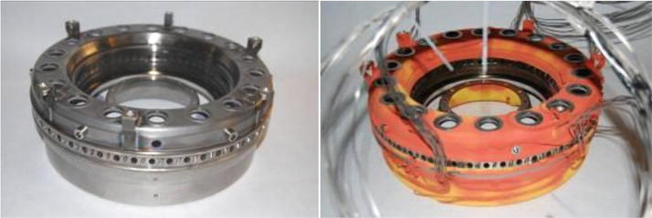
UTRC (United Technologies Research Center) and P&W Canada validated the SiC/SiC combustor in a PW 200 series combustor [10], as shown in Figure 4. The fill annular CMC combustor rig was engine tested for 250 cycles between idle (40,000 rpm) and full power (57,000 rpm) and severely tested the response of the CMC/metal interfaces to accelerated thermal cycling. The test was stopped after 250 cycles, with no damage observed.
Figure 4.
MI SiC/SiC combustor before and after rig test [10].
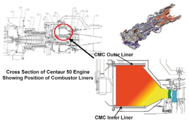
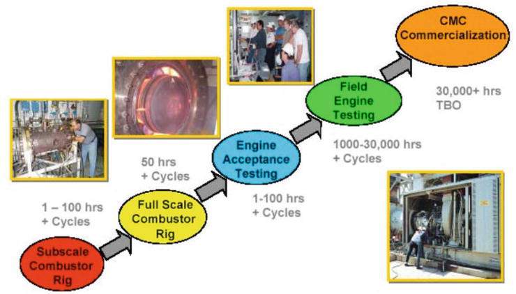
Solar Turbines Incorporated developed and evaluated both SiC/SiC and oxide/oxide combustor liners in test rigs and Solar Centaur® 50S engines since 1992 [11], as shown in Figure 5. The development roadmap includes the rig testing of subscale combustors, full-scale liner tests in atmospheric and high-pressure combustor rigs, and in-house and field testing in actual production engines, as shown in Figure 6. Table 1 lists the engine field test of the CMC combustor liner on the Centaur® 50S engine. Test durations of 15,144 hrs and 13,937 hrs were conducted on the SiC/SiC liners with protective environmental barrier coatings (EBCs), and 12,582 hrs were conducted for oxide/oxide liner with a Friable Graded Insulation (FGI) coating. NOx and CO emissions were < 15 ppmv and < 10 ppmv, respectively.
Figure 5.
The SiC/SiC inner linear and oxide/oxide outer liner tested on Solar Centaur 50S combustor [11].
Figure 6.
Solar’s CMC combustor liner development roadmap [11].
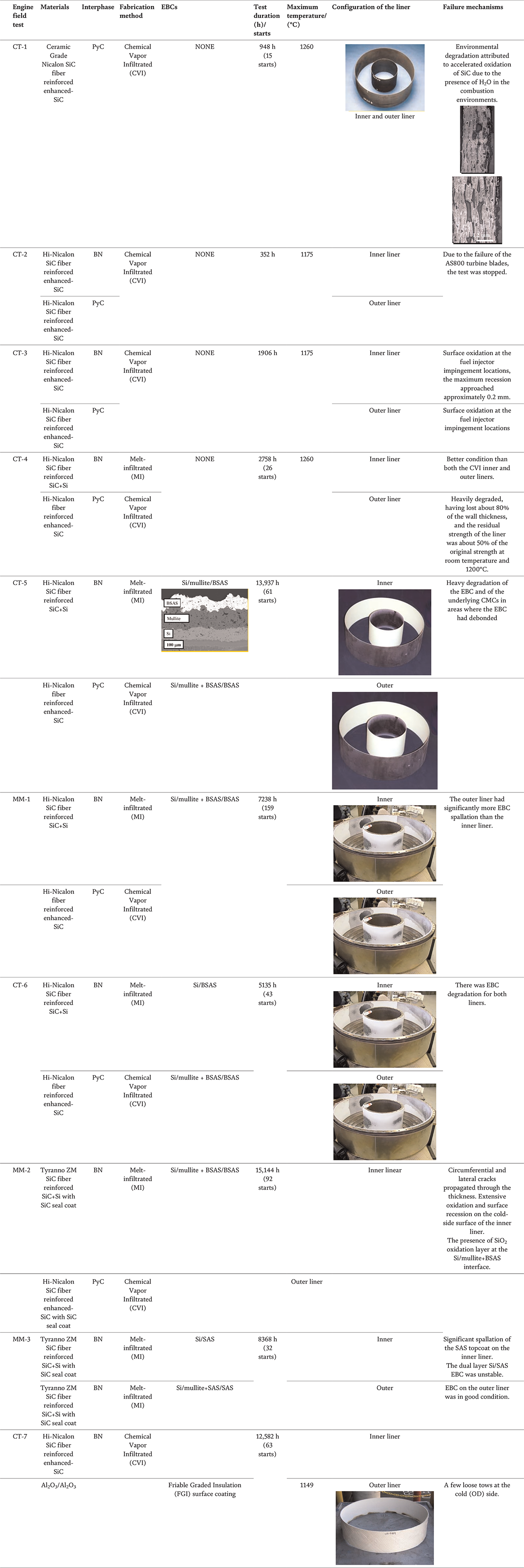
Table 1.
Engine field test of CMC combustor liner in centaur 50S engine.
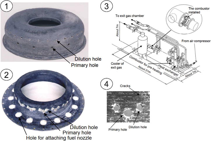
The Kawasaki Heavy Industries, Ltd. developed the uncooled three-dimensional Tyranno ZMI™ SiC fiber reinforced SiC matrix composite liners using the polymer impregnation and pyrolysis (PIP) process [12, 13], as shown in Figure 7. The low cycle fatigue (LCF) test was carried out, and the test condition was varied periodically from the idle to the design point. 65 cycle test was finally carried out until the first detection of cracks by bore-scope inspection.
Figure 7.
SiC/SiC combustor liner developed by Kawasaki heavy industries. ① SiC/SiC outer liner. ② SiC/SiC inner liner. ③ Test facility. ④ Cracks near dilution holes on the inner liner.
German aerospace center developed the oxide/oxide tubular combustor liner for a lean combustor in a future aero engine in the medium thrust range and tested at engine conditions [14, 15, 16], as shown in Figure 8. The tubular CMC combustion chamber and the EBC were in good condition.
Figure 8.
Oxide/oxide combustor liner developed by German Aerospace Center [15]. ① Oxide/oxide combustor liner for component test. ② Fit check with the oxide/oxide combustor liner. ③ Before the test. ④ After the test.
2.2 Application on turbine components
2.2.1 Turbine guide vanes
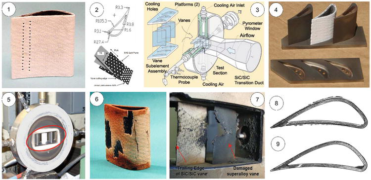
In the United States, under NASA’s Enabling Propulsion Materials and Ultra Efficient Engine Technologies programs, the SiC/SiC turbine guide vane was developed [17], as shown in Figure 9. The vane consisted of six plies of 2D Sylramic™ SiC fiber cloth (Y-cloth) reinforced with a CVI/slurry-cast/melt-infiltrated SiC/Si matrix. An environmental barrier coating (EBC) consisting of a silicon bond coat, a mullite intermediate coat, and a proprietary rare earth silicate topcoat was deposited on the SiC/SiC guide vane. Cooling holes were machined in the trailing edge using laser drilling prior to the application of the EBC. Three guide vanes with Haynes 188 superalloy vanes were tested using NASA’s High-Pressure Burner Rig (HPBR) for 50 hrs of steady-state operation and 102 thermal cycles. The minimum gas temperature ranged from 900 to 1050°C, and the maximum temperature ranged from 940 to 1440°C. After 50 hrs testing, about 26% of the total coating surface area had spalled. After thermal cycle tests, melting of the superalloy vanes occurred; however, the SiC/SiC vanes were intact with deposits on the EBC surface.
Figure 9.
NASA GRC development and testing of CVI/slurry-cast/melt-infiltrated SiC/SiC turbine guide vanes. ① SiC/SiC guide vane with EBC and cooling holes. ② Geometry of the guide vane and Y-cloth architecture. ③ Configuration of testing section. ④ SiC/SiC guide vane and superalloy vanes. ⑤ Installed SiC/SiC vanes and superalloy vanes in the test section. ⑥ SiC/SiC guide vane after steady state rig testing underwater exposure for 3.5 h. ⑦ SiC/SiC guide vane and superalloy vanes after thermal cycle tests. ⑧ NDE inspection of SiC/SiC vane after thermal cycle tests. ⑨ NDE inspection of SiC/SiC vane after steady state rig testing.
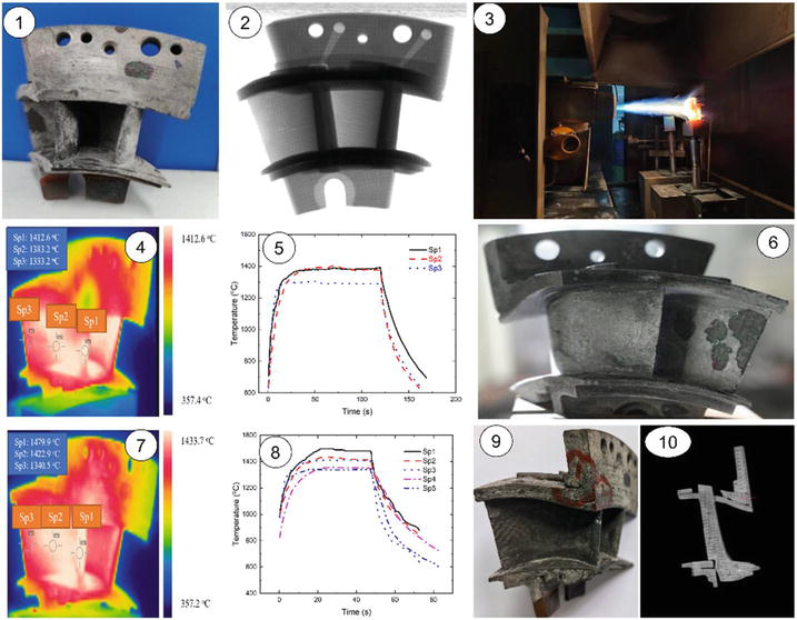
In China, the National Key Lab of Thermostructure Composite Materials at Northwestern Polytechnical University designed and tested the CVI SiC/SiC high-pressure turbine twin-guide vanes [18], as shown in Figure 10. The 2D lamination with Z-direction puncture fiber preform was adopted for the guide vane with the fiber volume of 40–45% in total. The PyC interphase was deposited on the surface of the SiC fiber with a thickness of 300–500 μm. After the deposition of the SiC matrix using the CVI method, the SiC coating was deposited on the guide vane using the chemical vapor deposition (CVD) method to protect the internal fibers from oxidation under thermal shock tests. Cyclic thermal shock tests at target temperatures of 1400, 1450, and 1480°C in gas environment were conducted to analyze the damage mechanisms and failure modes. When the temperature increased from 1400 to 1480°C, the spalling of the SiC coating occurred at the guide vane, and delamination occurred at the area near the trailing edge of the guide vane. Under the observation of X-ray computed tomography (XCT), no obvious damage inside of the guide vane was observed.
Figure 10.
Design, fabrication, and testing of CVI SiC/SiC high-pressure turbine twin-guide vane by the National key lab of Thermostructure composite materials in Northwestern Polytechnical University [18]. ① SiC/SiC turbine guide vane after fabrication and machining. ② NDE observation of SiC/SiC turbine guide vane before the testing. ③ Thermal shock testing of SiC/SiC turbine guide vane. ④ Surface temperature distribution at a target temperature of 1400°C. ⑤ Monitored temperature changes during a thermal shock cycle for 1400°C. ⑥ Surface observation after 400 thermal shock cycles at 1400°C. ⑦ Surface temperature distribution at target temperature of 1480°C. ⑧ Monitored temperature changing during a thermal shock cycle for 1480°C. ⑨ Surface observation after 200 thermal shock cycles at 1480°C. ⑩ NDE observation of SiC/SiC turbine guide vane after 200 thermal shock cycles at 1480°C.
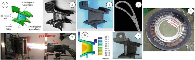
In Japan, the IHI Corporation developed the SiC/SiC turbine guide vane and tested it in the IHI IM270 industrial gas turbine engine [19], as shown in Figure 11. The braided fabrics were used for the hollow airfoil portion, and 2D-woven cloth and 3D-orthogonal woven fabrics were used for the outer/inner platform portion. The Tyranno ZMI SiC fiber with the boron nitride (BN) interphase reinforced SiC matrix was fabricated using the chemical vapor infiltration (CVI), solid phase infiltration (SPI), and polymer impregnation and pyrolysis (PIP) methods. Cyclic thermal shock test for SiC/SiC vane was conducted by burner rig. The maximum temperature was set to 1200°C. One thousand thermal cycles were conducted with 6 mins for each thermal cycle. After thermal cyclic tests, the cracks were found at the leading edge due to the machining. The engine test was conducted on the IHI IM270 with four SiC/SiC vanes installed into the first-stage turbine nozzle assembly. The engine test was conducted for 413 hrs with 48 starts and normal stops. The inlet gas temperature was about 1050°C at steady state.
Figure 11.
Design, fabrication, and testing of SiC/SiC turbine guide vane for the first stage of the IHI-IM270 engine [19]. ① Fiber arrangement of the SiC/SiC turbine guide van. ② SiC/SiC turbine guide vane as molded. ③ SiC/SiC turbine guide vane after machining. ④ X-ray CT of SiC/SiC turbine guide vane. ⑤ Burner rig test of SiC/SiC turbine guide vane. ⑥ Temperature distribution during burner rig test. ⑦ SiC/SiC turbine guide vane after burner rig test. ⑧ Engine test on IHI IM270.
2.2.2 Turbine blades
In France, Herakles has designed and manufactured SiC/SiC (Cerasep® A40C) turbine blades for the low-pressure turbine of a CFM56-5B engine [20], as shown in Figure 12. The subsequent tests of SiC/SiC blades performed by SNECMA in 2010 in an engine were a world first.
Figure 12.
Cerasep® A40C low-pressure turbine blade developed by Herakles [20].
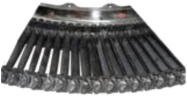
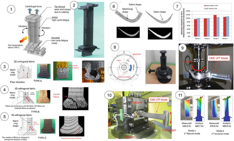
In Japan, the IHI Corporation designed and tested the SiC/SiC low-pressure turbine blade [21], as shown in Figure 13. The Tyranno ZMI SiC fibers were selected as the reinforcing fibers, and the boron nitride (BN) interphase was deposited on the SiC fiber by the CVI method to protect the SiC fibers from oxidation at elevated temperature. The fiber architecture for the main airfoil portion of the turbine blade was 3D orthogonal woven fabric with a fiber volume of 44%. The SiC matrix was fabricated using the chemical vapor infiltration (CVI), solid phase infiltration (SPI), and polymer impregnation and pyrolysis (PIP) methods. Three different types of dovetails were designed and tested under static pull at room temperature.
Figure 13.
Design, fabrication, and testing of SiC/SiC low-pressure turbine blade by IHI Corporation [21]. ① Configuration and load types of low-pressure turbine blade. ② Prototype of SiC/SiC turbine blade. ③ Type A dovetail and failure mode under static pull test. ④ Type B dovetail and failure mode under static pull test. ⑤ Type C dovetail and failure mode under static pull test. ⑥ Machining type and net shape type for the airfoil portion. ⑦ Natural frequency of machining type and net shape type for different modes. ⑧ Spin test for tip shroud. ⑨ Spin test for turbine blade. ⑩ High cycle fatigue test for turbine blade. 11 Measured mode shapes and natural frequencies with FEM analysis.
Type A dovetail with 3D orthogonal fabric were fractured in transverse shear mode at dovetail tongue, and the fracture loads for two specimens were 19.3 and 27.3 kN. Type B dovetail with 3D orthogonal fabric and 2D fabric was fractured in tensile mode at dovetail neck, and the fracture strength was the highest, i.e., 36.3 kN. Type C dovetail with 3D fabric was fractured in the transverse shear mode with a fracture strength of 16.7 kN. Cyclic load tests for type A, B, and C dovetail with the same configuration were conducted under the peak load of 4.7 kN, minimum load of 0.49 kN, and a loading frequency of 0.5 Hz at room temperature. No defect was found after 15,000 cycles for the three types of dovetail. After the static pull tensile and cyclic load tests, Type B dovetail was chosen for the creep and cyclic test under pull load of 4.7 kN at elevated temperature of 650°C. Under cyclic load, the Type B dovetail specimen experienced 100,000 cycles without failure, and under creep load, Type B dovetail specimen tested for 500 hrs without failure. The durability of type B dovetail was proved.
For the airfoil portion, the machining type and net shape type were manufactured. Modal tests were conducted for the two airfoil types, and the natural frequency of Mode 1 and 2 were measured and compared with the finite element method (FEM) analysis.
For the tip shroud, type A fins hooked onto folded fabric and type B fins stitched on the middle position of the shroud were designed and manufactured. Spin tests and rubbing tests were conducted for the type A and B tip shrouds at room temperature. During the spin test, both type A and B specimens remained stable for 5 mins under a centrifugal load at 130% maximum rotation speed in an actual engine. During the rubbing tests, the maximum amount of wear was about 0.5 mm.
For the SiC/SiC low-pressure turbine blade, the spin test was conducted to check the static strength. No defect was found after the steady state for 5 mins under the centrifugal load at 120% maximum rotation speed in the actual engine. A high cycle fatigue test was conducted at the first flexural mode frequency. After 107 cycles, no defect was found, and the natural frequency did not change.
2.2.3 Turbine blisk
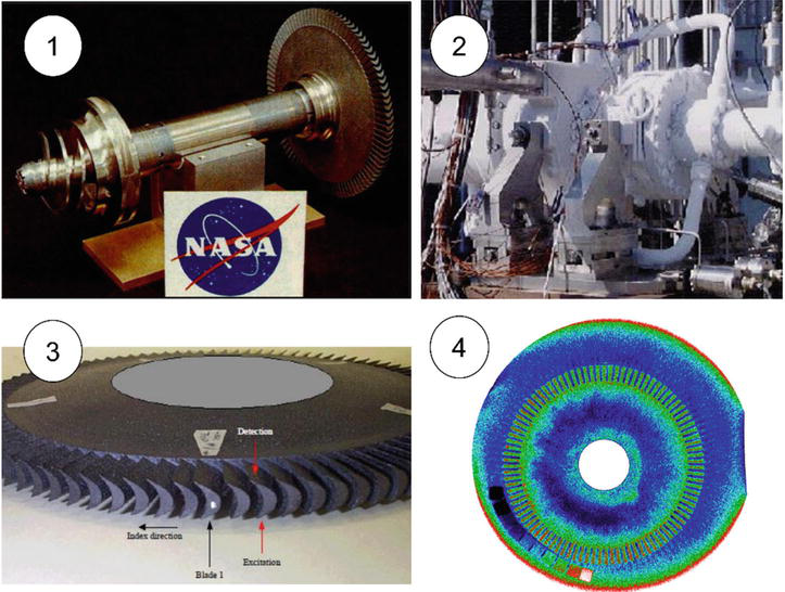
In the United States, under the NASA SIMPLEX Turbopump Blisk program, the C/SiC blisk prototype for rocket engine was manufactured by NASA Glenn Research Center (GRC) and George C. Marshall Space Flight Center (MSFC) using the CVI method and tested in the SIMPLEX Turbopump at NASA-MSFC Test Stand [22], as shown in Figure 14. One blisk was constructed with a polar woven fiber preform, and the second blisk was constructed with a quasi-isotropic preform. Two C/SiC blisks were tested in a rig under environmental conditions. The CT scan was used to analyze the internal defects of the fabricated blisk. The 2D and 3D C/SiC bench-top test specimens and C/SiC blisk specimens with quasi-isotropic and polar woven fiber architectures showed that the material was very lightly damped with high frequency-dependent damping.
Figure 14.
C/SiC turbine blisk for rocket engine developed by NSAS-GRC [22]. ① C/SiC turbine blisk installed on a shaft. ② SIMPLEX Turbopump. ③ C/SiC turbine blisk. ④ CT image of polar woven C/SiC blisk.
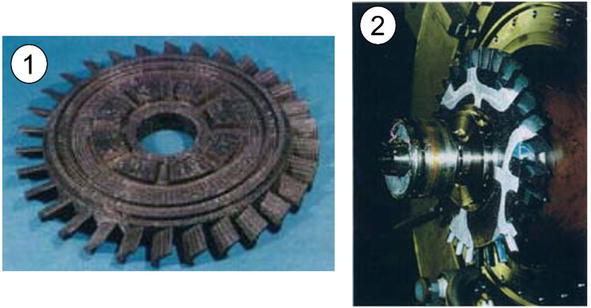
In Japan, under the research and development program of Advanced Material Gas-Generator (AMG) initiated in 1993, the SiC/SiC turbine blisk was machined from the disk fabricated by 3D woven SiC fiber densified with SiC matrix using CVI and PIP method [23], as shown in Figure 15. The blisk was mounted to the metallic shaft and rotated at 30000 RPM (tip rotational speed of 386 m/s) by exposing blade section to 973 K gas stream with no vibration and no damage observed.
Figure 15.
SiC/SiC turbine blisk developed by Japan [23]. ① SiC/SiC turbine blisk. ② Rig test of SiC/SiC turbine blisk.
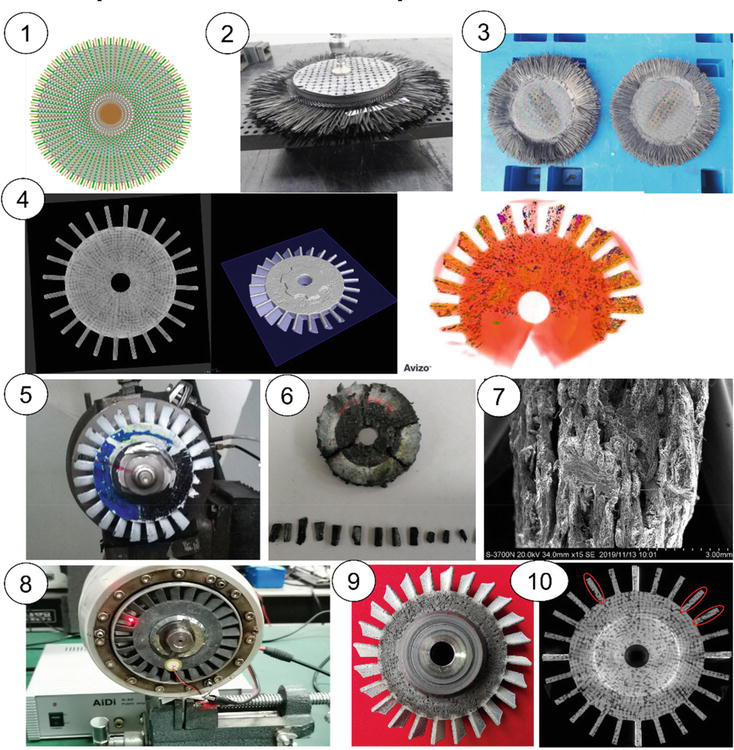
In China, the National Key Lab of Thermostructure Composite Materials in Northwestern Polytechnical University designed and tested the SiC/SiC turbine blisk [24], as shown in Figure 16. During the engine bench test, low cyclic fatigue of N = 994 cyclic with maximum speed nmax = 60,000 RPM and N = 100 cyclic with maximum speed nmax = 70,000 RPM were completed.
Figure 16.
Design, fabrication and testing of SiC/SiC turbine blisk [24]. ① Schematic of the spider web structure (SWS) fiber preform for turbine blisk. ② SWS fiber preform for turbine blisk. ③ SWS fiber preform with deposited SiC matrix using CVI method. ④ CT detection and 3D reconstruction analysis of SiC/SiC turbine blisk. ⑤ Overspeed rotation test of SiC/SiC turbine blisk at room temperature. ⑥ Blade flying off of the SiC/SiC turbine blisk. ⑦ Fragment scanning electron microscope (SEM) image. ⑧ SiC/SiC turbine blisk installation for the engine test. ⑨ Surface observation of SiC/SiC turbine blisk after engine test. ⑩ CT detection of SiC/SiC turbine blisk after engine test.
2.3 Application of exhaust components
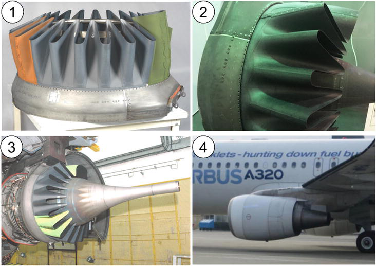
In France, the first technology demonstration dedicated to the evaluation of a CMC mixer for a CFM56-5C engine, powering the A340–200/300 jets, was conducted by SAFRAN [20], as shown in Figure 17. The component showed a 30% weight saving over Inconel. The prototype mixer manufactured with Cerasep® A40C was ground tested in 2007 and completed 700 engine cycles and 70 take-off hours with no material damage identified.
Figure 17.
Cerasep® A40C mixer developed by SAFRAN [20]. ① Cerasep® A40C mixer demonstration. ② Side photo of Cerasep® A40C mixer demonstration. ③ Cerasep® A40C mixer installed on CFM56-5C engine. ④ Flight testing of Cerasep® A40C mixter on A320.
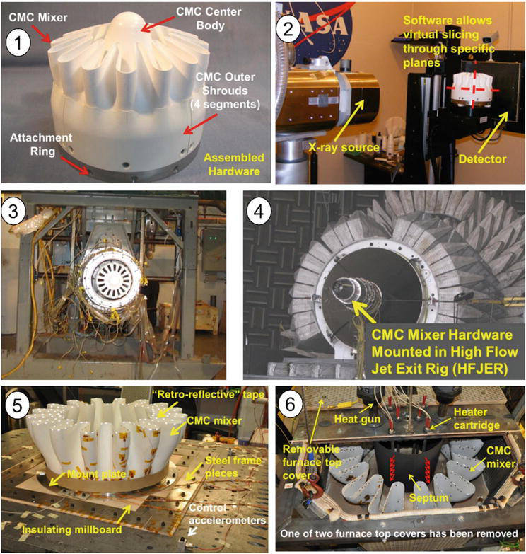
In the United States, the NASA Glenn Research Center (GRC) and Rolls-Royce Liberty Works (RRLW) teamed with ATK-COIC in the NASA ERA (Environmentally Responsible Aviation) project with the goal of advancing oxide/oxide mixer nozzle technology to full-scale engine testing [25], as shown in Figure 18. A subscale oxide/oxide exhaust mixer with 10 lobes and a diameter of approximately 200 mm was manufactured and tested in several rigs. The vibration test was completed in the GRC Structural Dynamic Lab in July 2014, including sine sweeps and dwells. Two 1 million cycle dwells were performed at room temperature, and one 100,000 cycle dwell was performed at 371°C. The deformation of the lobes was observed, and only three minor defects were observed.
Figure 18.
Oxide/oxide exhaust mixer developed and tested under the NASA ERA program [25]. ① Oxide/oxide subscale mixer and center body. ② NDE for the subscale oxide/oxide mixer and outer shrouds. ③ Performance testing of oxide/oxide exhaust mixer. ④ Nozzle acoustic test rig with oxide/oxide exhaust mounted. ⑤ Vibration testing of full-scale oxide/oxide exhaust mixer at room temperature. ⑥ Vibration testing of full-scale oxide/oxide exhaust mixer at elevated temperature.
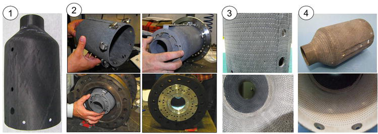
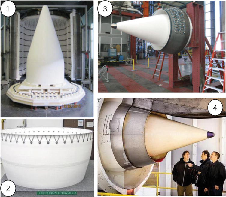
Under the continuous Lower Energy, Emissions, and Noise (CLEEN) Technologies Development Program, the Boeing Company is working to produce an acoustic Nextel 610/aluminosilicate composite centerbody and exhaust nozzle for commercial aircraft [26, 27], as shown in Figure 19. In 2014, Boeing tested the oxide/oxide nozzle on a 787 aircraft. This nozzle technology can withstand higher temperatures, and lower fuel consumption, and can also accommodate acoustic treatments that reduce community noise.
Figure 19.
Development and testing of oxide/oxide exhaust nozzle for the Trent 1000 engine by Boeing Company under CLEEN program of the FAA [23]. ① Oxide/oxide centerbody. ② Oxide/oxide outer ring. ③ Oxide/oxide exhaust nozzle assembly. ④ Ground engine testing of the oxide/oxide exhaust on Trent 1000.
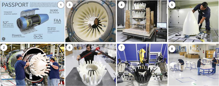
GE company developed an oxide/oxide exhaust mixer of 610 mm long and 965 mm in diameter and core cowling for Passport 20 engine powered by the Bombardier Global 7000 and 8000 ultra-long-range twinjets [28], as shown in Figure 20. The oxide/oxide exhaust mixer enabled a weight saving of approximately 20 ks compared to the metallic baseline.
Figure 20.
Development, fabrication, and installation of an oxide/oxide exhaust mixer for Passport 20 engine [28]. ① Passport 20 engine developed by GE company. ② Installation of oxide/oxide exhaust mixer on Passport 20 engine. ③ Oxide/oxide hand layup on metal molds. ④ Oxide/oxide mixer after curing at sintering furnace. ⑤ Milling, grinding and drilling of oxide/oxide centerbody. ⑥ Quality control checking on the outer surface of the mixer. ⑦ Nondestructive inspection on oxide/oxide mixer using infrared ash thermography. ⑧ Assembly of the metal and ceramic parts.
Ceramic-matrix composites possess high specific strength and modulus, especially at elevated temperatures. The CMCs hot-section components were developed by France, USA, China, Japan, etc., and have already been applied in military or commercial aero engines. This chapter reviews the recent design, application, and challenges of ceramic-matrix composites in hot-section components for gas turbine engines, including the CMC combustor liner, turbine guide vanes, turbine blades, turbine blisk, and exhaust mixer. In these applications, the non-oxide SiC/SiC and oxide/oxide CMCs were the main composites for engineering applications in hot-section components of aero engines. In the future, more and more CMC components will be used in commercial and military engines. To ensure the operation reliability and safety, damage mechanisms, failure modes and related models and prediction tools should be developed.
The author declares that he has no known competing financial interests or personal relationships that could have appeared to influence the work reported in this chapter.
References
1.Li LB. Ceramic Matrix Composites: Lifetime and Strength Prediction under Static and Stochastic Loading. Oxford, UK: Elsevier; 2023
3.Guo X, Wu J, Li J, Zeng Y, Huang X, Li LB. Damage monitoring of 2D SiC/SiC composites under monotonic and cyclic loading/unloading using acoustic emission and natural frequency. Ceramics-Silikaty. 2021;65:125-131
4.Liu H, Li L, Wang Y, Zhou Y, Ai Y, Yang J, et al. In situ damage propagation and fracture in notched cross-ply SiC/SiC composites: Experiment and numerical modeling. Journal of the European Ceramic Society. 2024;44:2052-2064
5.Li L. Characterization of multi-step cyclic-fatigue hysteresis behavior of 2D SiC/SiC composite using inverse tangent modulus. Ceramics International. 2024;50:4392-4403
6.Lü X, Li L, Sun J, Yang J, Jiao J. Microstructure and tensile behavior of (BN/SiC)n coated SiC fibers and SiC/SiC minicomposites. Journal of the European Ceramic Society. 2023;43:1828-1842
7.Lacombe A, Spriet P, Alain A, Bouillon E, Habarou G. Ceramic matrix composites to make breakthroughs in aircraft engine performance. In: 50th AIAA/ASME/ASCE/AHS Structural Dynamic, and Materials Conference; May 4–7, 2009; Palm Springs, California, USA. Reston, VA, USA: The American Institute of Aeronautics and Astronautics; 2009
8.Misra AK. Development of advanced engine materials in NASA ultra efficient engine technology program. In: Louisiana:15th International Symposium on Air Breathing Engines Conference. 2001
9.Padture NP. Advanced structural ceramics in aerospace propulsion. Nature Materials. 2016;15:804-809
10.Bhatia T, Jarmon D, Shi J, et al. CMC combustor liner demonstration in a small helicopter engine. In: ASME Turbo Expo 2010: Power for Land, Sea, and Air. Glasgow: American Society of Mechanical Engineers Digital Collection; 2010. pp. 509-513
11.Van Roode M, Price J, Kimmel J, Miriyala N, Leroux D, Fahme A, et al. Ceramic matrix composite combustor liners: A summary of field evaluations. Journal of Engineering Gas Turbines Power. 2007;129:21-30
12.Suzuki Y, Satoh T, Kawano M, Akikawa N, Matsuda Y. Combustion test results of an uncooled combustor with ceramic matrix composite liner. In: ASME Turbo Expo 2001: Power for Land, Sea, and Air; June 4–7, 2001; New Orleans, Louisiana, USA. New York, NY, USA: The American Society of Mechanical Engineers; 2001
13.Matsuda Y, Akikawa N, Satoh T. Manufacturing of 3-D woven SiCf/SiC composite combustor liner. In: 25th Annual Conference on Composites, Advanced Ceramics, Materials, and Structures: A: Ceramic Engineering and Science Proceedings. Hoboken, New Jersey, USA: John Wiley & Sons, Ltd; 2001. pp. 463-470
14.Gerenda M, Cadoret Y, Wilhelmi C, et al. Improvement of oxide/oxide CMC and development of combustor and turbine components in the HiPOC program. In: Proceedings of ASME Turbo Expo 2011; June 6–10, 2011; Vancouver, British Columbia, Canada. New York, NY, USA: The American Society of Mechanical Engineers; 2011
15.Gerendas M, Wilhelmi C, Machry T, et al. Development and validation of oxide/oxide CMC combustors within the HiPOC program. In: Proceedings of ASME Turbo Expo 2013: Turbine Technical Conference and Exposition; June 3–7, 2013; San Antonio, Texas, USA. New York, NY, USA: The American Society of Mechanical Engineers; 2013
16.Behrendt T, Hackemann S, Mechnich P, et al. Development and test of oxide/oxide ceramic matrix composites combustor liner demonstrators for aero-engines. Journal of Engineering for Gas Turbines and Power. 2017;139(3):031507
17.Verrilli M, Calomino A, Craig RR. Ceramic matrix composite vane subelement testing in a gas turbine environment. In: Proceedings of ASME Turbo Expo 2004, Power for Land, Sea, and Air; June 14–17, 2004; Vienna, Austria. New York, NY, USA: The American Society of Mechanical Engineers; 2004
18.Liu X, Guo X, Xu Y, Li LB, Zhu W, et al. Cyclic thermal shock damage behavior in CVI SiC/SiC high-pressure turbine twin guide vanes. Materials. 2021;14:6104
19.Fumiaki W, Takeshi N, Yousuke M. Design and testing for ceramic matrix composite turbine vane. In: Proceedings of ASME Turbo Expo 2017: Turbomachinery Technical Conference and Exposition GT2017; June 26–30, 2017; Charlotte, NC, USA. New York, NY, USA: The American Society of Mechanical Engineers; 2017
20.Patrick S. CMC applications to gas turbines. In Bansal NP, Lamon J: Ceramic Matrix Composites – Materials, Modeling and Technology. 1st ed. Hoboken, New Jersey: John Wiley & Sons, Inc.; 2014
21.Watanabe F, Nakamura T, Shinohara K. The application of ceramic matrix composite to low pressure turbine blade. In: Proceedings of ASME Turbo Expo 2016: Turbomachinery Technical Conference and Exposition, GT2016; June 13–17, 2016; Seoul, South Korea. New York, NY, USA: The American Society of Mechanical Engineers; 2016
22.Min J, Harris DL, Ting JM. Advances in ceramic matrix composite blade damping characteristics for aerospace turbomachinery applications. In: 52nd AIAA/ASME/ASCE/AHS/ASC Structures, Structural Dynamics and Materials Conference; 19th April 4–7, 2011; Denver, Colorado. Reston, VA, USA: The American Institute of Aeronautics and Astronautics; 2011
23.Kuriyama T, Miyagawa H, Uyama M, Yamamoto S, Yokoi S, Hiromatsu M. Status of AMG (Advanced Material Gas-Generator) research and development program. In: Proceedings of ASME TURBO EXPO 2001; June 4–7, 2001; New Orleans, Louisiana, USA. New York, NY, USA: The American Society of Mechanical Engineers; 2001
24.Liu X, Xu Y, Li J, et al. Design, fabrication and testing of ceramic-matrix composite turbine blisk. Acta Materiae Compositae Sinica. 2023;40(3):1696-1706
25.Kiser JD et al. Oxide/oxide ceramic matrix composite (CMC) exhaust mixer development in the NASA environmentally responsible aviation (ERA) project. In: ASME Turbo Expo 2015: Turbine Technical Conference and Exposition, Montreal, Quebec. New York, NY, USA: The American Society of Mechanical Engineers; 2015
26.Boeing. Continuous lower energy, emissions and noise (CLEEN) technologies development. In: The CLEEN Consortium Meeting. Arlington County, Virginia, USA: Boeing; 2011
27.Petervary M, Steyer T. Ceramic matrix composites for structural aerospace applications. In: 4th International Congress on Ceramics. Chicago, IL; 2012
28.Composites World: Ceramic Matrix Composites: Hot Engine Solution. 2017. Available from: https://www.compositesworld.com/articles/ceramic-matrix-composites-hot-enginesolution [Accessed: December 21, 2021]
Written By
Longbiao Li
Submitted: 08 January 2024Reviewed: 20 February 2024Published: 22 March 2024