Open Access is an initiative that aims to make scientific research freely available to all. To date our community has made over 100 million downloads. It’s based on principles of collaboration, unobstructed discovery, and, most importantly, scientific progression. As PhD students, we found it difficult to access the research we needed, so we decided to create a new Open Access publisher that levels the playing field for scientists across the world. How? By making research easy to access, and puts the academic needs of the researchers before the business interests of publishers.
We are a community of more than 103,000 authors and editors from 3,291 institutions spanning 160 countries, including Nobel Prize winners and some of the world’s most-cited researchers. Publishing on IntechOpen allows authors to earn citations and find new collaborators, meaning more people see your work not only from your own field of study, but from other related fields too.
Steel fiber-reinforced concrete (SFRC) is a composite material, consisting of conventional concrete with the addition of short, randomly distributed steel fibers. Fibers modify the mechanical behavior of concrete, improving some of its properties: they increase its ductility, enhance its residual tensile strength, and under certain conditions, increase its ultimate flexural strength. All these advantages make this material competitive with conventional reinforced concrete. However, the psychological barriers of the construction sector and the technical challenges that remain to be solved are slowing down the consolidation of this building material. One of these challenges is the improvement of the understanding of fatigue, which not only affects SFRC, but concrete in general. In this regard, work to date suggests that fibers, given certain circumstances, increase the fatigue life of concrete. This would result in SFRC being very effective in structures where fatigue is a critical action, such as wind turbine concrete towers.
Fiber-reinforced concrete is a composite material used in construction. It is defined as a type of concrete that includes in its composition short, discrete, and randomly distributed fibers in its matrix (Figure 1) [1]. It should be noted that current standards only consider steel fiber-reinforced concrete (SFRC) as a structural material [1, 2]. This is because the degree of development is much higher compared to other fibers, such as polypropylene, carbon, or glass.
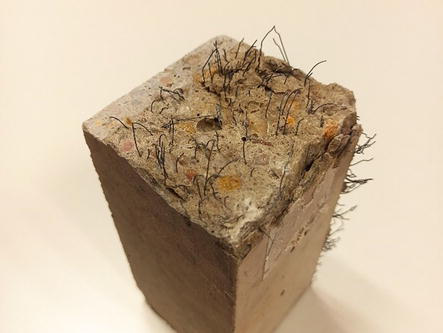
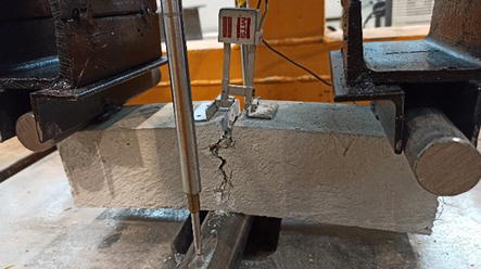
Figure 1.
Cracking surface of a steel fiber-reinforced concrete specimen.
The function of fibers is to make up for the shortcomings of conventional concrete, such as brittleness and very low tensile strength. In this sense, fibers increase the capacity of concrete to absorb deformation energy, making it much more ductile. Additionally, they enhance the residual tensile strength, or even the ultimate tensile strength [3, 4]. This leads to multiple benefits from the point of view of its structural functionality.
The use of fibers to improve the properties of building materials is an ancestral technique, which originated more than 10,000 years ago in adobe blocks, made of mud reinforced with straw. In the case of concrete, the addition of fibers began to be applied at the beginning of the 20th century, practically after the emergence of modern concrete made with Portland cement. The first patents using steel fibers to improve the mechanical response of concrete were those of Graham (1911, USA) and Alfsen (1918, France). During the following decades, patents continued to be developed, using mainly steel and glass fibers.
In the 1950s and 1960s, the research and development of fiber-reinforced concrete gained momentum. The efforts of researchers focused on perfecting the geometry of the fibers to solve the problems of workability and lack of adhesion to the concrete matrix, which were very common at this stage. In this regard, the work of Romualdi in the mid-1960s stands out [5, 6]. At this time, steel fiber-reinforced concrete began to be commonly used in applications such as high-performance pavements, foundations for heavy machinery, and air-raid shelters.
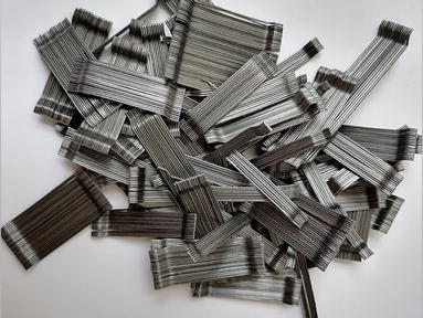
During the following decades and up to the present, very significant advances have been made in the performance of SFRC. One of them is the fibers with shaped ends (Figure 2), which improve adhesion with respect to straight fibers, increasing the ductility of the material [7, 8]. Another is gluing (Figure 2), which reduces the risk of fiber balling during batching, facilitating the use of very slender fibers, which are much more structurally efficient.
Figure 2.
Glued steel fibers with shaped ends.
Not only the improvement of steel fibers has contributed to the development of SFRC, but also the appearance of additives, among which superplasticizers, stands out. These admixtures make it possible to compensate for the worsening of consistency and workability caused by fibers without increasing the water/cement ratio and therefore without impairing the mechanical response of the concrete [9, 10].
This set of advances has made it possible to broaden the field of application of SFRC, which extends from the construction of pavements to withstand heavy loads and impacts, to the lining of subway works in the form of fiber-reinforced shotcrete. However, there are still significant technical and psychological barriers to giving fibers a greater structural responsibility, so that they partially or totally replace conventional rebar reinforcement. Therefore, the scientific community continues to move forward with the common goal of establishing SFRC as a structural material.
This chapter presents the latest scientific advances in the study of the mechanical behavior of steel fiber-reinforced concrete. Section 2 describes the components of SFRC, as well as some notions on dosage criteria. Section 3 describes the strength mechanism of SFRC. Section 4 then presents the mechanical properties of this material. Section 5 discusses the fatigue response of SFRC, a field of research that is currently attracting a lot of interest. Finally, Section 6 presents the conclusions.
Steel fiber-reinforced concrete consists of a concrete matrix to which the fibers are added. The components of the matrix are the same as those of conventional concrete: cement, water, aggregates, additions, and admixtures. However, the design of SFRC presents certain differences, as the addition of fibers modifies the properties of concrete, affecting the requirements of the rest of the components.
The most relevant aspects of each component of SFRC are described below, as well as the most common dosage criteria.
2.1 Cement
The type of cement used in the manufacture of SFRC is the same as that used in conventional concretes. When high strength is sought, cement with a high strength class is used, such as Portland cement CEM I 52.5 R [11].
As for the cement content, it is usually high, with minimum dosages of about 400 kg/m3. This is an essential requirement to achieve high strength, but there are also other reasons for this. Increasing the volume of cement paste improves the workability of concrete, counteracting the negative effect of the fibers. On the other hand, it is becoming increasingly common to work with self-compacting SFRC, which has multiple advantages, such as better workability or the absence of vibration. This type of concrete requires a large amount of fines to maintain cohesion and avoid segregation problems.
2.2 Water
There are no special requirements for the water used in the manufacture of SFRC, other than the usual ones, such as avoiding the use of types of water likely to promote fiber corrosion and chemical attack on the concrete matrix.
The water/cement (w/c) ratio is low, in the order of 0.4. This is a condition for obtaining high strength. If the w/c ratio was high, a significant volume of water would not react with the cement, causing an increase in porosity and thus a decrease in strength.
2.3 Aggregates
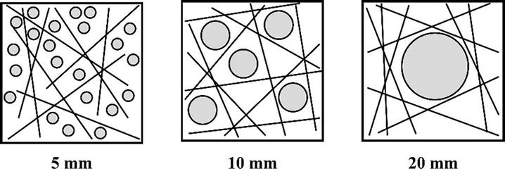
The aggregates that constitute concrete can be classified into three large groups according to their size: coarse aggregate or gravel (>2 mm), fine aggregate or sand (<2 mm and > 0.063 mm), and fines (<0.063 mm). The design of a suitable particle size is essential in the manufacture of SFRC, as it directly affects consistency, workability, and strength.
As for the coarse aggregate, it must be small enough to allow adequate fiber distribution (Figure 3). For this reason, it is recommended that the ratio between coarse aggregate size and fiber length be a maximum of 0.5 [1]. With respect to the fine aggregate, its quantity is usually high, with fine aggregate/coarse aggregate ratios greater than 1. In this way, segregation problems are avoided and fiber distribution in the matrix is favored. Finally, a high fines content is very important, as it improves workability and increases cohesion. The minimum fines content should be about 500 kg/m3, which can be added in the form of filler or by means of pozzolanic additions, such as silica fume.
Figure 3.
Effect of aggregate size on fiber distribution [12].
2.4 Admixtures
As mentioned above, fibers reduce the fluidity of concrete, worsening its workability. To solve this problem, water can be added, but this would lead to a decrease in concrete strength. In this context, the use of superplasticizing admixtures is highly recommended. These admixtures improve the consistency of fresh concrete without increasing the w/c ratio.
The dosage of the superplasticizing admixture will be indicated by the manufacturer, and it is not usual to exceed 4% by the weight of cement. It should be mentioned that an excessive amount of superplasticizer may result in problems of segregation or exudation of the cement paste.
2.5 Fibers
Fibers are the differentiating component of SFRC with respect to conventional concrete and are what give it the status of a composite material. They are linear elements of short length and small sections that are added to the concrete matrix to improve some of its properties. In addition to steel fibers, discussed here, there are many other types: polypropylene, glass, carbon, natural, and so on.
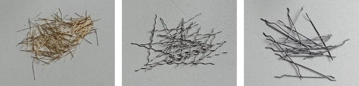
Fibers can have different shapes, such as straight, wavy, serrated, crimped, with hooked ends or with flat ends (Figure 4). The most common ones are straight and hooked-end fibers. It is important to emphasize that fiber geometry significantly influences fiber-matrix adhesion and thus the mechanical response of SFRC. Higher adhesion increases the energy absorption capacity of the material and therefore its ductility.
Figure 4.
Types of steel fibers. From left to right, straight, crimped, and hooked-end.
The main geometrical properties of fibers are length and slenderness. On the one hand, certain criteria have to be considered when choosing the fiber length. A maximum fiber length to minimum mold or formwork dimension ratio of 1/3 is recommended [13, 14]. This reduces the wall effect, which causes the fibers closest to the mold to tend to be oriented parallel to the mold faces. The control of this phenomenon is very important, especially when extrapolating laboratory results, obtained on small samples, to full-scale structures.
On the other hand, fiber slenderness, defined as the ratio between length and diameter, is related to their mechanical efficiency. For the same volume of fibers, the greater the slenderness, the greater the adhesion to the matrix and the ductility of the SFRC. However, very high slenderness (>100) considerably reduces the workability of concrete and favor the formation of fiber balls.
Table 1 shows the average values of the main properties of steel fibers.
Geometrical properties
Length (mm)
10–60
Equivalent diameter (mm)
0.2–1.0
Slenderness
45–80
Material and mechanical properties
Modulus of elasticity (GPa)
>200
Tensile strength (MPa)
500–3000
Elongation at break (%)
2–7
Density (kN/m3)
78.5
Table 1.
Properties of steel fibers for SFRC.
Fiber content is expressed as the weight of fibers per unit volume of concrete (kg/m3) or as the percentage of fiber volume in relation to the volume of concrete. The minimum dosage of fibers when they fulfill a structural function is of the order of 20 kg/m3, while the maximum, limited by the decrease in workability, is in the range of 160 kg/m3. In any case, the most common range of fiber contents is between 25 and 95 kg/m3.
The main function of the fibers is to withstand tensile stresses because, as mentioned above, the tensile strength of plain concrete (PC) is low.
Consider an SFRC beam subjected to a three-point bending test (Figure 5). As the load increases, so does the maximum tensile stress. As long as the stress is low, the tensile stress will be supported by the concrete matrix, with little involvement of the fibers. This will continue until concrete cracks, i.e., until the stress corresponding to the first crack strength is reached, which is approximately around 3–5 MPa. At this point, a process of progressive transfer of tensile stresses from the matrix to the fibers will begin. Finally, when concrete is in a fully cracked state, the fibers will be the only ones responsible for supporting the tensile stresses.
Figure 5.
Three-point bending test on the SFRC specimen. The final phase in fully cracked state.
Steel fibers have two main failure mechanisms: pull-out, due to the exhaustion of the tangential bond stresses with the matrix (τ > τmax) and breakage, due to the exhaustion of the normal tensile stresses (σ > σmax). In practice, fiber failure in SFRC is mostly due to pull-out, i.e., most commonly, the ultimate tangential pull-out bond stress τmax is reached earlier than the ultimate tensile normal stress σmax. This is positive from the point of view of structural safety as the pull-out failure mode is more progressive and ductile.
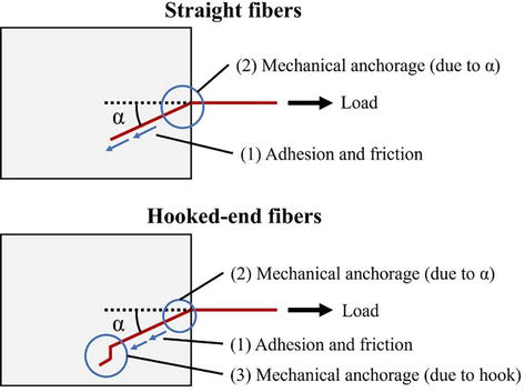
The strength of steel fibers against pull-out depends significantly on fiber geometry. The two most common types will be analyzed: straight and hooked-end. In addition, it will be considered that fibers have a certain inclination with respect to the crack plane, as, being randomly distributed, it is not expected that they are perfectly orthogonal to it.
When a straight fiber is subjected to tension, the acting mechanisms are adhesion, friction, and mechanical anchorage due to inclination (Figure 6) [15]. Adhesion is the force that binds the fiber to the concrete matrix and depends on the microstructure of the fiber-matrix interface. Friction is the force that is mobilized when the fiber is partially or completely detached from the matrix. Finally, when the fiber is tilted, the force acting in the direction of its axis is a part of the total pull-out force, thus generating a mechanical anchoring effect.
Figure 6.
Pull-out strength mechanisms in straight and hooked-end fibers.
It is observed that mechanical anchorage has a positive impact on pull-out behavior, that is, fibers that have a certain inclination with respect to the crack plane have more pull-out strength than those that are perfectly orthogonal to it (Figure 7). The pull-out strength increases with the inclination of the fibers up to a certain angle, after which it decreases drastically, as the failure occurs by the detachment of the concrete cover. According to several studies, the optimum angle of inclination for which the maximum pull-out strength occurs ranges from 30° to 60°, although it depends on fiber geometry and matrix properties [16, 17].
Figure 7.
Approximate force vs. displacement diagrams in pull-out tests of straight and hooked-end fibers with and without inclination.
On the other hand, in hooked-end fibers, the mechanisms that act when subjected to tensile stress are the same as those of straight fibers and in addition the mechanical anchorage by the hooked end (Figure 6). In this case, the impact of the anchorage due to the hook is very significant, with two fundamental results. First, the pull-out strength is higher than that of straight fibers. Secondly, the influence of the inclination on the pull-out strength is much lower than for straight fibers. In fact, for moderate inclinations (up to 30°), and depending on fiber and matrix properties, pull-out strength remains constant [16, 18]. However, it is worth mentioning that, although the inclination does not necessarily increase the strength, it does increase the energy absorbed by the fibers (Figure 7).
From the above, it is concluded that hooked-end fibers are more efficient than straight fibers, as the additional mechanism generated by the hook increases both the pull-out strength and the ductility.
Some of the characteristics of plain concrete are high compressive strength, very low tensile strength, and brittleness at breakage. The presence of fibers causes these properties to change to a greater or lesser extent. The main mechanical properties of SFRC are described below.
4.1 Compressive strength
Numerous authors conclude that the addition of fibers, as well as an increase in their content, do not necessarily improve the compressive strength of concrete [19, 20, 21]. This is explained by the balance between two opposing effects: on the one hand, the positive effect of the bridging forces generated by the fibers, which reduces the occurrence and growth of cracks and on the other hand, the negative effect of the reduction of fluidity that they induce, increasing porosity.
In any case, fibers do affect the stress-strain diagram (σ-ε). It is observed that the strain under maximum load is higher in SFRC than in plain concrete, which is explained by the ductility they provide. In addition, SFRC may have a certain residual compressive strength capacity, which is not observed in PC.
4.2 Modulus of elasticity
It is observed that the usual fiber contents do not produce relevant improvements of the modulus of elasticity, so it can be assumed that it remains constant [21].
This is due to the fact that the modulus of elasticity characterizes the linear-elastic behavior of concrete. At this stage, it can be considered that concrete is intact and has not yet cracked. Therefore, due to strain compatibility, the matrix resists practically the entire load, while the fibers have hardly been mobilized. Consequently, the stiffness of the SFRC in this range is the stiffness of the matrix, i.e., the same as that of plain concrete.
4.3 Tensile strength
In general, the ultimate direct tensile strength of SFRC is not higher than that of PC. However, when certain conditions are met, an increase in tensile strength is observed. This is the case for ultra-high-performance fiber-reinforced concrete, characterized by high energy absorption capacity and strain hardening behavior [4]. Some of the factors contributing to achieve these properties are high fiber content (≥1% or 78.5 kg/m3) and to a lesser extent high slenderness (≥70), efficient fiber geometry (e.g., hooked-end fibers), and good fiber-matrix adhesion.
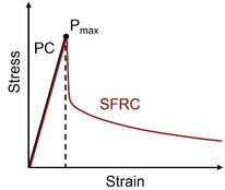
Although, in conventional SFRC, the addition of fibers does not lead to an increase in direct ultimate tensile strength, a significant increase in residual tensile strength is observed. As Figure 8 shows, in the σ-ε diagram of PC, once the maximum stress is reached, there is a sharp drop due to highly brittle failure. However, in SFRC, after reaching the maximum stress, the drop is not so pronounced and fibers are able to withstand a certain level of stress up to high deformations. This residual strength contribution is known as strain softening.
Figure 8.
Stress–strain diagram in plain concrete and fiber-reinforced concrete under uniaxial tension.
4.4 Flexural strength
The flexural behavior of SFRC is very different from that of PC. In all cases, a very significant increase in residual flexural strength is observed. As for the maximum flexural strength, its value can be maintained or increased, which depends on a set of factors: fiber volume, slenderness, typology, fiber-matrix adhesion, and orientation, among others. However, it should be noted that fibers have a much greater impact on the flexural response of concrete than on the direct tensile response [4]. In other words, the requirements of SFRC components to achieve flexural strength greater than that of plain concrete are lower than in the case of uniaxial tension. For example, in some works, an increase in flexural strength is observed with relatively low fiber contents (0.6%) [21, 22].
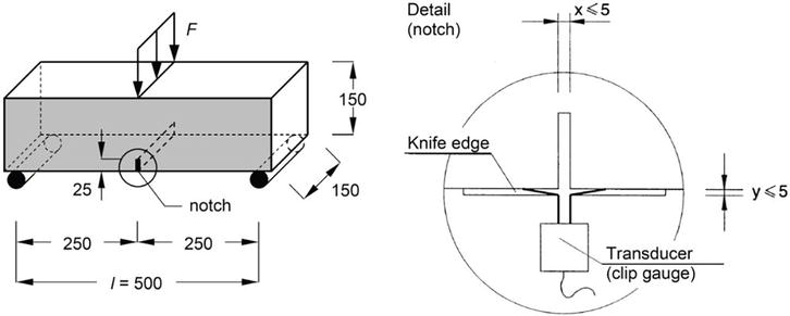
Standardized tests to evaluate the flexural strength of SFRC consist of prismatic specimens, with or without notching, subjected to bending at three or four points. The most common is the one described in EN 14651 (Figure 9) [14], equivalent to RILEM TC 162-TDF [23]. It is a three-point bending test performed on 150 × 150 × 600 mm prismatic specimens with a 25 mm deep central notch.
Figure 9.
SFRC flexural test configuration according to [14].
The main result of a flexural test in SFRC is the stress-crack opening (CMOD) diagram. Figure 10 compares this diagram in PC and various types of SFRC.
Figure 10.
Stress-CMOD (crack mouth opening displacement) diagram of flexural test on plain concrete and steel fiber-reinforced concrete with different behaviors.
Figure 10 shows that the first section with linear-elastic behavior is the same in all cases. This is because concrete has not yet cracked, and therefore, the fibers have not been mobilized. From this, it can be concluded that the first crack strength (Pf) depends exclusively on the matrix, at least for normal fiber contents.
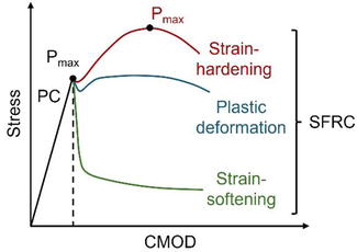
When concrete cracks, brittle fracture of the specimen occurs in PC. However, in SFRC, three situations can occur:
Strain-softening: the bridging forces of the fibers do not withstand more stress than the matrix, so the stress decreases with crack opening. However, a certain residual stress and thus a significant increase in strain energy absorption capacity is observed. In this case, the ultimate flexural strength coincides with the first crack strength (Pmax = Pf).
Plastic deformation: the strength mechanism of the fibers supports a stress similar to that of the matrix, so that the stress remains sensibly constant up to high values of CMOD. In this situation, it is observed that the maximum flexural strength is approximately equal to the first crack strength (Pmax = Pf). However, the difference with respect to the previous case is that the residual strength is much higher.
Strain hardening: the bridging forces of the fibers are able to withstand more stress than the matrix, which increases the maximum flexural strength. This maximum load occurs for high CMODs due to the ductility provided by the fibers. This is the only case where Pmax > Pf, that is, where the maximum flexural stress is greater than that of plain concrete. This increase varies depending on the characteristics of the SFRC and can be more than 100%.
These three situations can also be observed in direct tensile tests, although with much higher fiber contents. It is possible to have an SFRC that shows strain-softening under direct tension, but strain-hardening under bending.
4.5 Fatigue
As the fatigue behavior of SFRC is a field of research of great scientific interest at present, this issue will be addressed separately in Section 5.
4.6 Other mechanical properties
In addition to those already mentioned, the addition of steel fibers improves other concrete properties, such as impact strength and abrasion resistance. Additionally, fibers can increase the durability of concrete, as they control cracking, distributing it, and reducing the crack width. This hinders reinforcement corrosion and increases resistance to chloride attack, among others.
Fatigue is defined as a process of mechanical degradation of a material leading to its failure, which occurs when it is subjected to cyclic loading. This phenomenon is of great interest because it implies that a given element can collapse without ever having exceeded its strength under static conditions.
In the case of concrete, the study of fatigue is very interesting for several reasons. First, practically, all concrete structures are subjected to cyclic loading, to a greater or lesser extent. Thus, there are structures that undergo few load cycles, but with a very high stress level (such as a building subjected to an earthquake), while others support a large number of cycles with a low stress level (such as a dam subjected to waves). Secondly, fatigue is an increasingly relevant phenomenon, and all structural codes devote more space to it, as, with the advance of high-strength concrete, structures are becoming increasingly slender. As a result, the importance of variable loads (wind, traffic, etc.), which are cyclic in nature and therefore susceptible to fatigue, is growing. In fact, in structures such as wind turbine concrete towers, fatigue is the dimensioning action.
Thirdly, and related to the above, concrete fatigue has a wide dispersion of results, being common that the fatigue life of two identical elements subjected to the same load cycles can vary by up to two orders of magnitude. This lack of knowledge of the phenomenon leads structural codes to be very conservative in fatigue design. Finally, the field of flexural fatigue has been of great scientific interest in recent years, particularly in steel fiber-reinforced concrete. This is because the fibers are able not only to provide residual flexural strength but also to increase the ultimate flexural strength itself. It is expected that, in the coming years, structural solutions based on SFRC will be competitive with the current reinforced concrete solutions.
5.2 Impact of fibers on the fatigue response of concrete
The addition of fibers modifies the mechanical characteristics of concrete, and therefore its fatigue response. There are numerous works that study the influence of the presence and content of fibers on the fatigue life of concrete; that is, on the number of stress cycles between certain maximum and minimum levels that a given element can withstand until failure.
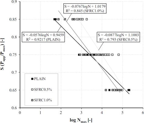
Germano et al. [24] carried out an experimental study of flexural fatigue in SFRC, considering different fiber contents (0%, 1%, and 2%) and load levels (15–65%, 25–75%, and 35–85% with respect to the static flexural strength). The results are very interesting (Figure 11). On the one hand, it is observed that the fatigue life of SFRC is higher than that of PC for high load levels; however, this positive effect decreases with decreasing load levels. On the other hand, in all cases, the fatigue life of specimens with 0.5% fibers is higher than those with 1% fibers. This suggests that there is an optimum fiber content in terms of fatigue response.
Figure 11.
Stress-number of cycles (S-N) curves for plain concrete and SFRC with fiber contents of 1% and 2%, according to [24].
Other research also suggests that fibers improve the fatigue life of concrete, although only up to a given content [25, 26, 27]. Vicente et al. [26] performed flexural fatigue tests on precracked specimens with fiber contents of 1 and 2%. They concluded that, while the residual flexural strength increased with the number of fibers, the fatigue life remained practically constant. Poveda et al. [25] studied the influence of different fiber contents (from 0 to 0.8% by volume) on the compressive fatigue response of self-compacting concrete. They observed that the optimum fiber content, for which the fatigue life increased by up to five times compared to that of plain concrete, was 0.6%. Moreover, at 0.8% and above, there was a marked decrease in fatigue life, attributed to the increase in porosity induced by the high fiber content.
In summary, it can be concluded that the addition of fibers improves the fatigue response of concrete, both in bending and compression, but only under certain conditions of load levels and fiber contents. Therefore, further research in this field is required to obtain more robust results.
The factor related to the fibers that have been most studied with regard to fatigue strength is the content; however, there are others that may be relevant, such as fiber typology, slenderness, or orientation. In the case of orientation, most publications analyze its influence on the static response of concrete. It is shown that the residual flexural strength increases when the fibers are more perpendicular to the crack plane [28, 29]. With respect to fatigue, one of the few publications is that of Vicente et al. [30], which studies the influence of orientation on the compressive fatigue of SFRC. By applying microcomputed tomography, they conclude that the fatigue life is higher when the fibers are arranged more perpendicular to the loading axis. This is explained by the bridging forces of the fibers, which prevent the propagation of vertical cracks.
5.3 Fatigue damage
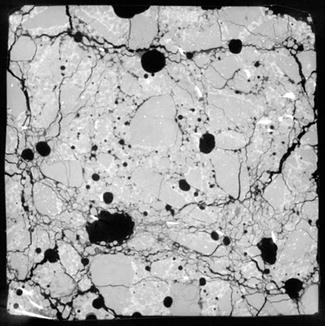
Cyclic fatigue loading causes progressive damage to the concrete. This damage manifests itself internally with the appearance and growth of cracks. Fatigue cracks originate in the weakest zones of the SFRC, which are the coarse aggregate-matrix and fiber-matrix interfaces [30, 31] (Figure 12).
Figure 12.
Microcomputed tomography image showing compressive fatigue damage in a cubic SFRC specimen [30].
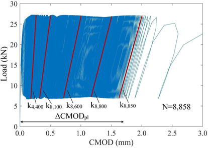
Microstructural fatigue damage is reflected at the macrostructural level by some indicators, allowing it to be analyzed quantitatively. In compressive fatigue, fatigue cycles cause changes in the stress-strain diagram. In particular, there is an increase in the residual strain and a reduction in the dynamic modulus of elasticity [32]. Equivalently, in flexural fatigue, variations in the load-CMOD diagram are observed (Figure 13): an increase in the plastic or residual crack opening (CMODpl) and a decrease in stiffness (ki) defined as the slope of the loading branch of each cycle [24, 33, 34].
Figure 13.
Load-CMOD diagram in a flexural fatigue test on SFRC [22].
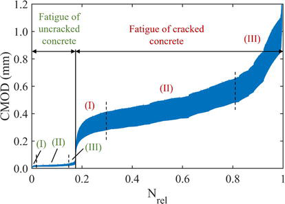
Another diagram that allows analysis of the mechanical degradation of concrete due to flexural fatigue is the cyclic creep curve. It is the upper envelope of the CMOD vs. number of cycles diagram. In the most general case of a flexural fatigue test in SFRC (with a configuration as shown in Figure 5), this diagram looks like the one in Figure 14.
Figure 14.
CMOD vs. relative number of cycles diagram in SFRC subjected to flexural fatigue [21].
Figure 14 clearly distinguishes two mechanisms of fatigue damage. First, there is a first phase in which the concrete has not cracked and the loads are supported by the matrix, with little intervention of the fibers. This mechanism is known as “fatigue of uncracked concrete” (in green in Figure 14) and consists of the following stages: (I) plastic tensile deformation and birth of microcracks at the notch edge, (II) stable growth of the microcracks, and (III) convergence into a main macrocrack that triggers failure. Second, when this mechanism is exhausted and concrete cracks, “fatigue of cracked concrete” (in red in Figure 14) begins. The stages are (I) concrete cracking and fiber loading, (II) stable propagation of the main macrocrack due to progressive fiber failure, and (III) unstable propagation of the macrocrack until failure. Once this second mechanism is exhausted, the collapse of the element occurs.
As can be seen, fatigue of cracked concrete is a much more ductile mechanism (higher CMOD variations) than fatigue of uncracked concrete. This is because the loads are supported by the bridging forces of the fibers, which are less stiff than those of the concrete matrix.
It is worth mentioning that, in SFRC, the fatigue of uncracked concrete does not always occur. This requires that the maximum fatigue stress level be lower than the first crack strength. Otherwise, the concrete would crack after the first loading cycle.
Finally, there is a parameter of the cyclic creep curves that is of great interest because of its relationship with fatigue strength. Figure 14 shows that, in both fatigue mechanisms, stage (II) can be fitted to a straight line. The slope of this line is called the crack opening rate (dCMOD/dn). Several studies show that there is a clear correlation between the crack opening rate and fatigue life, such that the lower the dCMOD/dn, the higher the N [21, 24, 33]. This experimental relationship, known as the Sparks and Menzies relationship [35], was originally proposed in compressive fatigue. Its major utility is that it helps to understand the experimental dispersion of fatigue and can serve as a basis for the development of more robust fatigue design criteria.
Steel fiber-reinforced concrete is a composite building material that has undergone great development in terms of mechanical performance in recent years. However, the great inertia toward change in the construction sector, together with technical challenges still unresolved, meaning that SFRC has not yet been consolidated as a structural material of reference.
SFRC is basically a type of concrete to which short, discrete, and randomly distributed steel fibers are added. However, the addition of fibers affects the requirements of the other components. In general, a larger volume of cement, smaller coarse aggregate, and superplasticizing admixtures are needed to improve workability without compromising strength.
Fibers improve the fracture behavior of concrete, resulting in SFRC having a higher energy absorption capacity and thus higher ductility than plain concrete. In addition, the bridging forces of the fibers increase the tensile strength, which in PC is very low. In this sense, SFRC is particularly efficient in elements subjected to flexural stress.
The study of fatigue in SFRC is of great interest due to the possibilities it offers in structures where this action is dimensioning, such as wind turbine concrete towers. Several studies suggest that the addition of fibers increases the fatigue life of concrete, although only under certain load levels and fiber contents.
In conclusion, although there have been very relevant advances, there are still important technical challenges to be solved in order to optimize the mechanical behavior of steel fiber-reinforced concrete.
The authors are grateful for the financial support of the Spanish Ministerio de Economía y Competitividad (grant no. PID2019-110928RB-C32) and the Spanish Ministerio de Ciencia, Innovación y Universidades (grant no. FPU19/02685).
References
1.European Committee for Standardisation (CEN), EN 1992-1-1:2023. Eurocode 2 - Design of Concrete Structures - Part 1-1: General Rules and Rules for Buildings, Bridges and Civil Engineering Structures. Brussels, Belgium. 2023
2.International Federation for Structural Concrete (fib). Model Code 2010. Lausanne, Switzerland. 2012
3.Choi SW, Choi J, Lee SC. Probabilistic analysis for strain-hardening behavior of high-performance fiber-reinforced concrete. Materials. 2019;12:2399. DOI: 10.3390/ma12152399
4.Wille K, El-Tawil S, Naaman AE. Properties of strain hardening ultra high performance fiber reinforced concrete (UHP-FRC) under direct tensile loading. Cement and Concrete Composites. 2014;48:53-66. DOI: 10.1016/j.cemconcomp.2013.12.015
5.Romualdi JP, Mandel JA. Tensile strength of concrete affected by uniformly distributed and closely spaced short lengths of wire reinforcement. ACI Journal Proceedings. 1964;61:657-672. DOI: 10.14359/7801
6.Romualdi JP, Batson GB. Mechanics of crack arrest in concrete. Journal of the Engineering Mechanics Division. 1963;89:147-168. DOI: 10.1061/JMCEA3.0000381
7.Marcalikova Z, Cajka R, Bilek V, Bujdos D, Sucharda O. Determination of mechanical characteristics for fiber-reinforced concrete with straight and hooked fibers. Crystals (Basel). 2020;10:1-21. DOI: 10.3390/cryst10060545
8.Qiu M, Shao X, Zhu Y, Hussein HH, Li F, Li X. Effect of aspect ratios of hooked end and straight steel fibers on the tensile strength of UHPFRC. Journal of Materials in Civil Engineering. 2022;34(7). DOI: 10.1061/(asce)mt.1943-5533.0004283
9.de la Rosa Á, Poveda E, Ruiz G, Cifuentes H. Proportioning of self-compacting steel-fiber reinforced concrete mixes based on target plastic viscosity and compressive strength: Mix-design procedure & experimental validation. Construction and Building Materials. 2018;189:409-419. DOI: 10.1016/j.conbuildmat.2018.09.006
10.ACI Committee 544, ACI 544.3R-93. Guide for Specifying, Proportioning, Mixing, Placing, and Finishing Steel Fiber Reinforced Concrete. Farmington Hills, MI, USA. 1998
11.European Committee for Standardisation (CEN), EN 197-1. Cement. Part 1: Composition, Specifications and Conformity Criteria for Common Cements. Brussels, Belgium. 2011
12.Asociación Española de Hormigón Estructural. M-2. Manual de tecnología del hormigón reforzado con fibras de acero. Madrid, Spain. 2000
13.ASTM C1609/C1609M-12. Standard Test Method for Flexural Performance of Fiber-Reinforced Concrete (Using Beam with Third-Point Loading). West Conshohocken, PA, USA. 2012
14.European Committee for Standardisation (CEN), UNE-EN 14651. Test Method for Metallic Fibre Concrete. Measuring the Flexural Tensile Strength (Limit of Proportionality (LOP), Residual). Brussels, Belgium. 2008
16.Song F. Steel fiber reinforced concrete under concentrated load [thesis]. Germany: Ruhr-Universität Bochum; 2017
17.Poveda E, Yu RC, Tarifa M, Ruiz G, Cunha VMCF, Barros JAO. Rate effect in inclined fibre pull-out for smooth and hooked-end fibres: A numerical study. International Journal of Fracture. 2020;223:135-149. DOI: 10.1007/s10704-019-00404-7
18.Gebuhr G, Pise M, Sarhil M, Anders S, Brands D, Schröder J. Analysis and evaluation of the pull-out behavior of hooked steel fibers embedded in high and ultra-high performance concrete for calibration of numerical models. Structural Concrete. 2019;20:1254-1264. DOI: 10.1002/suco.201900034
19.Yang J, Chen B, Nuti C. Influence of steel fiber on compressive properties of ultra-high performance fiber-reinforced concrete. Construction and Building Materials. 2021;302(124104). DOI: 10.1016/j.conbuildmat.2021.124104
20.Gesoglu M, Güneyisi E, Muhyaddin GF, Asaad DS. Strain hardening ultra-high performance fiber reinforced cementitious composites: Effect of fiber type and concentration. Composites Part B: Engineering. 2016;103:74-83. DOI: 10.1016/j.compositesb.2016.08.004
21.Mena-Alonso Á, González DC, Mínguez J, Vicente MA. Size effect on the flexural fatigue behavior of high-strength plain and fiber-reinforced concrete. Construction and Building Materials. 2024;411:134424. DOI: 10.1016/j.conbuildmat.2023.134424
22.Mena-Alonso Á. Flexural fatigue of high-strength plain and fiber-reinforced concrete: influence of mesostructure and study of size effect [thesis]. Spain: University of Burgos; 2023. DOI: 10.36443/10259/7855
23.International Union of Laboratories and Experts in Construction Materials, Systems and Structures (RILEM), Recommendations of RILEM TC 162-TDF: Test and design methods for steel fibre reinforced concrete: Bending test. Paris, France. 2002
24.Germano F, Tiberti G, Plizzari G. Post-peak fatigue performance of steel fiber reinforced concrete under flexure. Materials and Structures. 2016;49:4229-4245. DOI: 10.1617/s11527-015-0783-3
25.Poveda E, Ruiz G, Cifuentes H, Yu RC, Zhang X. Influence of the fiber content on the compressive low-cycle fatigue behavior of self-compacting SFRC. International Journal of Fatigue. 2017;101:9-17. DOI: 10.1016/j.ijfatigue.2017.04.005
26.Vicente MA, Mínguez J, González DC. Computed tomography scanning of the internal microstructure, crack mechanisms, and structural behavior of fiber-reinforced concrete under static and cyclic bending tests. International Journal of Fatigue. 2019;121:9-19. DOI: 10.1016/j.ijfatigue.2018.11.023
27.Gao D, Gu Z, Zhu H, Huang Y. Fatigue behavior assessment for steel fiber reinforced concrete beams through experiment and fatigue prediction model. Structure. 2020;27:1105-1117. DOI: 10.1016/j.istruc.2020.07.028
28.Mínguez J, González DC, Vicente MA. Fiber geometrical parameters of fiber-reinforced high strength concrete and their influence on the residual post-peak flexural tensile strength. Construction and Building Materials. 2018;168:906-922. DOI: 10.1016/j.conbuildmat.2018.02.095
29.Mudadu A, Tiberti G, Germano F, Plizzari GA, Morbi A. The effect of fiber orientation on the post-cracking behavior of steel fiber reinforced concrete under bending and uniaxial tensile tests. Cement and Concrete Composites. 2018;93:274-288. DOI: 10.1016/j.cemconcomp.2018.07.012
30.Vicente MA, Ruiz G, González DC, Mínguez J, Tarifa M, Zhang X. Effects of fiber orientation and content on the static and fatigue behavior of SFRC by using CT-scan technology. International Journal of Fatigue. 2019;128:105178. DOI: 10.1016/j.ijfatigue.2019.06.038
31.Zhang J, Stang H, Li VC. Fatigue life prediction of fiber reinforced concrete under flexural load. International Journal of Fatigue. 1999;21:1033-1049. DOI: 10.1016/S0142-1123(99)00093-6
32.Holmen JO. Fatigue of concrete by constant and variable amplitude loading [thesis]. Norway: Division of Concrete Structures, Norwegian Institute of Technology, University of Trondheim; 1979
33.Carlesso DM, de la Fuente A, Cavalaro SHP. Fatigue of cracked high performance fiber reinforced concrete subjected to bending. Construction and Building Materials. 2019;220:444-455. DOI: 10.1016/j.conbuildmat.2019.06.038
34.Gebuhr G, Pise M, Anders S, Brands D, Schröder J. Damage evolution of steel fibre-reinforced high-performance concrete in low-cycle flexural fatigue: Numerical modeling and experimental validation. Materials. 2022;15:1179. DOI: 10.3390/ma15031179
35.Sparks PR, Menzies JB. The effect of rate of loading upon the static and fatigue strengths of plain concrete in compression. Magazine of Concrete Research. 1973;25:73-80. DOI: 10.1680/macr.1973.25.83.73
Written By
Álvaro Mena-Alonso, Dorys C. González, Jesús Mínguez and Miguel A. Vicente
Submitted: 20 January 2024Reviewed: 21 January 2024Published: 21 February 2024