
Abstract
Carbon supersaturation (CS) process was developed to prepare the CS-tool steel dies with massive carbon solute content toward the galling-free metal forming. The impinged carbon solutes diffused and agglomerated onto the hot spots at the die-work interface by stress gradient during the metal forming. This in situ formed free-carbon thin film worked as a tribofilm to reduce the friction and adhesive wear on the die-work interface. Titanium and titanium alloys were selected as a work material common to forging, near-net forming and fine blanking processes. The ball-on-disc method was employed to demonstrate the significant reduction of friction coefficient by CS-tool steels against the pure titanium ball. Upsetting process was used to describe the galling-free forging behavior even under the higher reduction of thickness than 50%. Pin-forming process was utilized to prove that taller pins than designed target were extruded and their height was preserved even with increasing the number of strokes. Fine blanking process was used to describe the integrity of CS-punch with higher grade of titanium gears. The in situ solid lubrication by formation of free-carbon tribofilm was discussed in each metal forming. In particular, the initial learning trial was proposed to shorten the incubation time for the free-carbon film coverage onto the hot spots.
Keywords
- galling-free forming
- titanium and titanium alloys
- In situ solid lubrication
- free-carbon tribofilm
- upsetting
- pin forming
- fine blanking
- high qualification of products
1. Introduction
Titanium and titanium alloys have been widely utilized in every industry and medical application [1]. During their metal forming, their fresh surfaces come into contact with the die surface, resulting in severe adhesion wear or galling damage to dies [2]. Hence, the lubrication is indispensable for their metal forming in practice. Manufacturing of eye-glass flames and medical parts disliked the contamination of lubricating oils; solid lubrication provides an only way to control the contact interface condition between the work and the dies [3, 4]. After [5], the bulk ceramic dies suffered from severe adhesion of pure titanium plate to lower the limit of deep drawability. The ceramic coatings, such as TiN, TiCN or TiAlN and DLC (Diamond-Like Coating), were not free from galling, so that higher friction coefficient than 0.2 was attained in the ball-on-disc testing [6]. As discussed in [7], the galling often occurs during hot forming processes even at the presence of solid lubricants and ceramic coatings under relatively small plastic strains. Among various solid lubrications, the in situ solid lubrication methods become only a solution to reduce the friction and wear on the die-work interface and to sustain low-frictional and wearing state although the steps in forming.
Figure 1 compares three methods for in situ solid lubrication [8]. The chlorine-implanted TiN and TiCN coatings had anti-galling capacity due to in situ formation of deformable titanium oxide (TiOx for 1 < x < 2) film on the contact interface [9, 10, 11], as depicted in Figure 1 a. Tetragonal DLC (t-a:C) coating, working in the tailored polymer lubricant, hindered the direct contact of work materials with DLC coating by in situ synthesis of polymer layer to attain the superlubrication conditions [12], as illustrated in Figure 1b. Using the carbon supersaturated ceramic, stainless steel and tool steel dies, the isolated carbon film from CS-dies was in situ formed on the contact die-work interface to lower the friction and wear [13, 14, 15, 16, 17, 18].
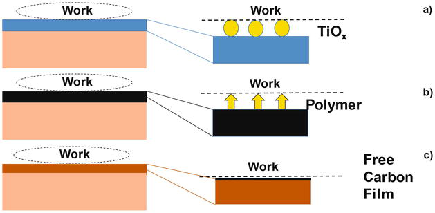
Figure 1.
Typical in situ solid lubrication mechanisms during the metal forming even in dry or in MQL (minimum quantity lubrication). a) In situ formation of deformable titanium oxide film (TiOx for 1 < x < 2) on the titanium base coating to work interface, b) in situ formation of monolayer polymer film onto the t-a:C coating and c) in situ formation of free-carbon film onto the CS-tool to work interface.
Among three solid lubricating mechanisms, the in situ formed carbon tribofilm works in practical metal forming, where the tool steel dies are used for dry and semi-dry forming of titanium and titanium alloys. This in situ formation of free-carbon tribofilms, in Figure 1c, is further explained in Figure 2.
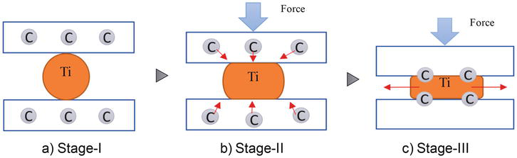
Figure 2.
Illustration of this in situ solid lubrication process. a) Stage-I: massive carbon supersaturation to tool steel dies, b) stage-II: diffusion and agglomeration of isolated free-carbon solutes from CS-dies and c) stage-III: formation of free-carbon tribofilm onto the highly stressed hot spots at the CS-tool to titanium work interface.
The lower temperature plasma carburizing process [13, 14, 15] was utilized for massive carbon supersaturation in tool steel or stainless steel dies. The plasma carburized dies at 673 K for 14.4 ks had a CS-layer with the thickness of 40 μm and the average carbon solute content of 3 mass%. Most carbon solutes occupy the octahedral vacancy sites in the iron lattice cells to induce the lattice expansion. The lattices in CS-layer strained in elasticity, while the neighboring cells to CS-layer plastically strained to compensate for the strain incompatibility across the carburizing front end. Due to this plastic straining, the original die microstructure was nano-structured to have the specific orientation to (111) or easy-to-deformation axis [19, 20]. In local, the carbon solute occupation had disturbance by its chemical affinity among iron/nickel and chromium, the constituent compositions in the stainless steels or tool steels. Then, this nanostructure had two-cluster decomposition system, where the carbon-rich cluster was neighboring to the carbon-poor cluster in the nano-structured CS-layer. The carbon solute was easy to isolate from its occupation sites and to jump to next sites through this fine cluster boundary network by externally applied driving force in Figure 2a [21, 22, 23].
On the true contact state between the fresh work material and the CS-dies during metal forming, high traction was applied to the hot spots at the contact interface. This high stress gradient induced the carbon solute jumping diffusion to the hot spots. These attracted free-carbon solutes by stress gradients, agglomerated on the hot spots and formed a free-carbon tribofilm to hinder the direct contact of work with CS-die surfaces in Figure 2b. During the metal forming, this tribofilm gradually grew and became a stable tribofilm on the CS-die to work interface in Figure 2c. As demonstrated in [24, 25, 26], this in situ solid lubrication mechanism via CS-tools and CS-dies played a significant role to reduce the friction, the wearing and the work hardening in forming and shaping of titanium and titanium alloys.
In the present chapter, this in situ solid lubrication process was experimentally described and analyzed to demonstrate its effectiveness to prevent the tools and dies from severe galling behavior in metal forming. First, the ball-on-disc method is employed to explain the gradual formation of the free-carbon tribofilm on the track of CS-disc with an increase in sliding distance. Low friction and wearing state are preserved in longer sliding distance against the pure titanium ball. In second, three metal forming processes are employed to actually prove that low friction and wearing state are also sustained by this in situ solid lubrication—e.g., forging, pin forming and fine blanking. Higher reduction of thickness than 50% is attained by a single-step upsetting process with low friction, low adhesive wear and low work hardening. A titanium round bar is continuously free forged to have a triangular cross-section beam within a single stroke. Taller pins than designed target are formed into the forged titanium frame in every stroke for mass production. This tall pin height is preserved although the extrusion steps in eye-glass frame manufacturing. A titanium gear with high dimensional accuracy and low surface roughness is continuously yielded by fine blanking without severe galling of titanium. High product qualification was also proved by dimensional comparison of products with and without carbon supersaturation. The features of this approach are discussed to improve the metal forming performance especially in its early stage and to extend this technology to other industrial and medical fields.
2. Methods and materials
The plasma carburizing system is explained with comments on the processing conditions for massive carbon supersaturation to tool steel dies. The ball-on-disc (BOD) testing and three metal forming procedures are stated to experimentally demonstrate the effectiveness of this in situ solid lubrication mechanism as a unique process tribological method for metal forming of titanium and titanium alloys.
2.1 Plasma carburizing process
RF (Radio-Frequency) and DC (Direct Current) generators were used in this plasma carburizing process to ignite and preserve the plasma-immersion conditions. This system consisted of RF- and DC-plasma generators, the driving gas suppliers, the evacuation unit and the EOS (Emission Optical Spectroscopy) unit for plasma diagnosis as illustrated in Figure 3a. The hollow cathode device was employed to keep high carbon-ion and CH-radical densities after this diagnosis and to deepen the carbon supersaturated layer thickness [27, 28, 29]. The dipole electrodes were utilized to ignite the RF plasma, while the DC plasma was also induced by applying the bias voltage to the bottom of hollow cathode. The RF-voltage and the DC-bias were constant by +210 V and − 500 V, respectively. The carburized layer thickness was estimated to be 40 μm in case of the plasma carburizing at 673 K for 18.0 ks by 50 Pa.
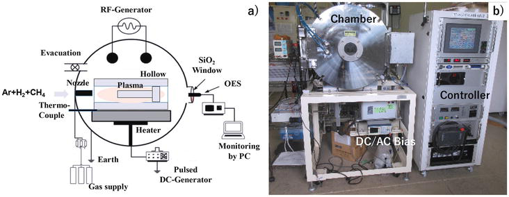
Figure 3.
Low temperature plasma carburizing system. a) Its schematic view of the ignition of plasmas in the hollow cathode and b) overview of the whole system.
The following procedure was employed in practical operation for plasma carburizing. After evacuation down to the base pressure of 0.01 Pa, the argon gas was introduced to a chamber at RT to clean the punch and die surfaces in Figure 3b via presputtering. After increasing the process temperature up to 673 K under the argon atmosphere, the hydrogen gas was also introduced into the argon gas with the flow rate of 160 mL/min for argon and 20 mL/min, respectively. The total pressure was constant by 50 Pa. After presputtering by the DC-plasmas for 1.8 ks, the methane gas was introduced as a carbon source into argon and hydrogen mixture gas by the flow rate of 20 mL/min. At the specified duration of 18.0 ks, the specimen was cooled down in the chamber under the nitrogen atmosphere before evacuation down to atmospheric pressure. The processing temperature was in situ monitored by the thermocouple, which was embedded into the base plate below the hollow cathode device.
2.2 Ball-on-disc testing
BOD tribotesting system (Tribometer; CSM, Switzerland) in the rotational mode was utilized to describe the frictional behavior between the CS-SKD11 disc and the pure titanium ball in Figure 4. The SKD11 disc with the diameter of 60 mm and the thickness of 5 mm was prepared for carbon supersaturation. The pure titanium ball with the diameter of 6 mm was used as a counter material. The friction coefficient (μ) was calculated by μ = F/W for the measured frictional force, F, and the applied normal load, W. The sliding velocity, V, was varied together with W to describe the variation of the friction coefficient with increasing the sliding distance, L, up to L = 500 m.
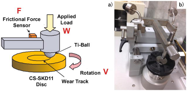
Figure 4.
Pure titanium ball to CS-SKD11 disc testing. a) Its schematic view of the rotational sliding test and b) overview of the whole setup.
2.3 Metal forming procedure
CNC (Computer Numerical Control)-stamping system (Hoden Seimitsu; Kanagawa, Japan) was employed for upsetting experiments with the use of two different CS-die pairs, as depicted in Figure 5.
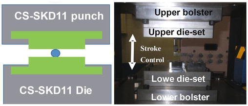
Figure 5.
Schematic view and overview of the upsetting process to uniaxially compress the titanium bar by CS-punch and die.
CS-SKD11 punch and die were, respectively, fixed into the upper and lower cassette die sets. Those two die sets were cemented to upper and lower bolsters of CNC-stamping system with the stroke control capability. The stroke was controlled to move down the upper bolster to the specified position for reduction of thickness in work materials. The loading speed was constant by 10 mm/s.
Figure 6 depicts the upsetting process to infiltrate the pure titanium work into the die cavities. Since a fresh titanium work contacts the cavity walls and die edges, this process has a risk of severe galling with high friction. This high wearing and friction results in shortage of pin height; the accumulated adhesion of titanium work onto them gradually reduces the pin height and increases the applied load.
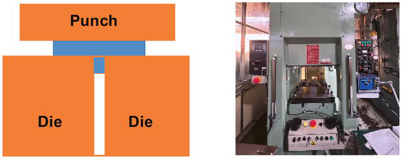
Figure 6.
Schematic view and overview of the pin-formation process to build up the pins into the titanium alloy frame.
Figure 7 shows the fine blanking process to shear out the titanium plate to bulk products under constraints and various applied loads. During this shearing process, the fresh titanium work has a risk of galling to the punch and die surfaces. This adhesive wear significantly reduces the punch life and lowers the product quality.
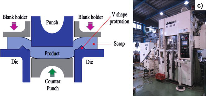
Figure 7.
Schematic view and overview of the fine blanking process to shear the thick titanium plate and to punch out the titanium product.
3. Tribology of CS-SKD11 dies
Variation of the measured friction coefficient (μ) with the sliding (L) was depicted in Figure 6 under the applied load (W) of 10 N and the sliding velocity (V) of 0.05 m/s. Except for the initial running distance, μ was preserved at 0.11 in average. μ and its deviation (Δμ) decreased from 0.15 to 0.10 and from 0.05 to 0.01, respectively. As discussed in [6], titanium debris stuck to TiN, TiCN and TiAlN coatings, resulting in higher friction coefficient than 1.0. This severe metal sticking was also observed on the wear track of Si-bearing DLC coating. No sticking was seen when using the nano-laminated DLC (n-DLC) coating; μ is nearly constant by 0.2. The surface textures and tribological conditions were varied to analyze their effect on the frictional transients in [30]. In every case, μ is more than 0.18. The stable and low-frictional state was preserved at CS-SKD11 disc against the pure titanium ball in dry.
SEM–EDX was utilized to analyze the wear-track surface of this CS-SKD 11 disc after sliding up to L = 500 m. As shown in Figure 8, no adhesion of pure titanium fragments was detected on this wear track except for a few TiO2 debris particles at the vicinity of wear-track edges. Most of wear-track surface was covered by carbon film. This analysis proves that low-frictional behavior in Figure 9 is attained by the in situ formation of free-carbon tribofilm onto the interface between CS-SKD11 disc and titanium ball. Let us consider the effect of sliding velocity on this low-frictional behavior. Figure 10 shows the variation of friction coefficient with increasing L under W = 10 N and V = 0.1 m/s. In the initial running, spiky increase of friction coefficient was detected twice before L = 100 m. For L > 100 m, the stable friction advanced by μ = 0.07. This implies that a stable free-carbon tribofilm is formed after an incubation time when the insufficient coverage of free-carbon film at the hot spots induces unstable surface conditions with high friction coefficients.
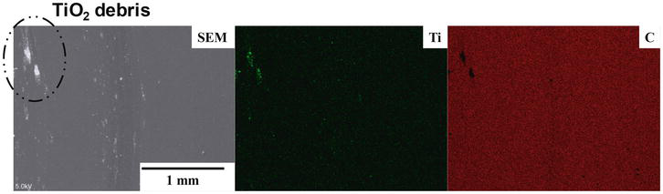
Figure 8.
SEM–EDX analysis on the wear track of CS-disc after sliding the pure titanium ball up to L = 500 m.
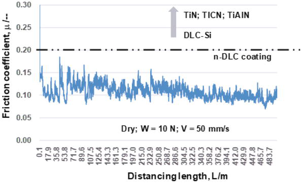
Figure 9.
Variation of the friction coefficient (μ) with increasing the sliding distance (L) up to L = 500 m under the applied load of 10 N and the sliding velocity of 0.05 m/s.
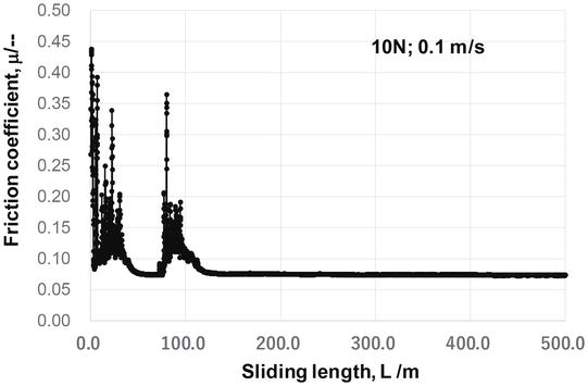
Figure 10.
Effect of the sliding velocity on the transients of friction coefficient with L. the applied load was 10 N and the sliding velocity was 0.1 m/s.
4. Upsetting of titanium and titanium alloys by CS-dies
A pure titanium round bar with the diameter of 1.0 mm was upset in dry without any liquid lubricants by CS-punch and CS-die in the specified reduction of thickness (r). Before upsetting, the surfaces of CS-punch and CS-die were completely polished not to leave any surfactants. At first, this pure titanium bar was upset in a single shot by r = 10%, 20%, 30%, 50% and 70%, respectively. Without carbon supersaturation treatment, this reduction of thickness was significantly reduced down to 10 to 15%. Aa shown in Figure 11, the round bar was upset to each r without adhesive wear on the contact interface.
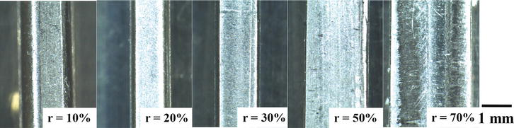
Figure 11.
Variation of the upset pure titanium round bar with increasing the reduction of thickness (r) up to r = 70%.
The width of upset bar (Wo), the contact interface width (Wi) and the bulging displacement, Bg (=(Wo-Wi)/2) were chosen as a parameter to describe this upsetting behavior. After [31], Bg is employed as a parameter to measure the frictional coefficient during the uniaxial compression. When Bg > 0.5, the friction coefficient governs the plastic deformation of work and a round bar significantly bulges by itself. On the other hand, the friction coefficient reduces when Bg < 0.5 or Bg ~ 0. Figure 12 shows the variation of Wo, Wi and Bg with r. Wo increases with r in quadratic, while Wi increases in linear with r. When r > 50%, Wi approaches Wo; at r = 70%, Bg ~ 0.0.
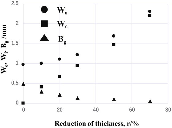
Figure 12.
Variation of the bar width (Wo), the contact interface width (Wc) and the bulging displacement (Bg) with increasing r.
This monotonous approach of Wi to Wo implies that the friction coefficient monotonically reduces itself with r and goes down to nearly zero. Then, Bg monotonously decreases with r and becomes nearly zero at r = 70%. After the regression curve between Bg and μ, μ is estimated to be 0.05–0.1, much lower than the friction coefficient with μ > 0.2 in the literature [6, 30]. This low-frictional behavior by CS-punch and die against the titanium bar is reconsidered by using the finite element analysis (FEA) [24]. In this inverse analysis, the friction coefficient is parametrically varied so that the measured micro-hardness map corresponds to the plastic strain calculated by FEA at the same reduction of thickness. Figure 13 compares the measured micro-hardness map to the calculated plastic strain at r = 50%, assuming that the friction coefficient is 0.05; that is, μ = 0.05 at r = 50%. Let us analyze the work-die interface using the SEM and EDX, where low friction is preserved even with increasing r. The contact interface area expands from the center line toward the upper and lower directions with increasing r. Then, without CS, the fresh titanium work could be easily in direct contact with the die surface to onset the galling. In this contact area, fine white stripes are seen along this area expansion in Figure 14a. EDX was utilized to identify the chemical component of these strips at the central region A in the contact interface. As compared in Figure 14b, no correlation is recognized between these stripes and constituent elements of SKD11, iron and chromium. A very few stripes correspond to the titanium and oxygen maps; the TiO2 debris particle sparsely adhered to the CS-punch surface. Almost all of white stripes in SEM images just correspond to carbon mapping. Since no stripes were detected before upsetting, these carbon stripes must be in situ formed on the interface. Raman spectroscopy was utilized to describe the binding state of these carbon white stripes. Since no significant peaks were found in the lower wave numbers in Figure 14c, the carbon was not present as a bound carbon in the carbides. Fine D-peak at Λ = 1320 cm−1 and G-peak at Λ = 1600 cm−1 prove that these stripes consist of free carbons, isolated from the CS-punch during upsetting.
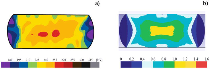
Figure 13.
Comparison of the experimentally measured micro-hardness map with the calculated plastic strain distribution by FEA. a) Measured micro-hardness map and b) calculated plastic strain.
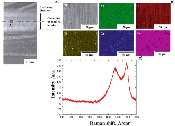
Figure 14.
Microstructure analysis on the contact interface between the CS-punch and the titanium bar after continuously upsetting the pure titanium bar 10 times up to r = 70%. a) SEM image on the contact interface, b) element mapping by EDX at the region a in (a, and b) Raman spectroscopy at the region a in (a).
As already discussed in [9, 32], a free carbon has no possibility to isolate from amorphous carbon layer or DLC coating at the absence of polymers and liquid lubricants. This implies that a free carbon directly isolated from CS-SKD11 die drives the low friction and wear condition at the hot spot in the contact interface to titanium works.
Let us compare the upsetting behavior between pure titanium and β-phase titanium alloy bars using the same CS-punch and CS-die. As suggested in [33], the pure titanium has hcp (Hexagonal close-packed) structure, while the β-phase titanium alloy has bcc (body-centered cubic) structure. Due to a fewer number of slipping planes, hcp-structured material is thought to have more difficulty in plastic straining than bcc-structured one. This difference is reflected in the upsetting behavior under nearly the same low-frictional interface to CS-punch and CS-die.
The micro-hardness mapping is employed to compare the plastic straining behavior between two bars under the same upsetting conditions as shown in Figure 15. Even when r = 10%, the β-phase titanium alloy bar has higher micro-hardness profile than the pure titanium bar. This reveals that the uniform plastic straining advances in the β-phase alloy more easily than the pure titanium. In both bars, work hardening is suppressed only at the center of bars in common since the CS-punch and CS-die are utilized in both cases. The hardness gradient, that is, the plastic strain gradient is much reduced even at higher reduction of thickness when using the β-phase alloy. This implies that uniform plastic straining with lower work hardening advances in upsetting the β-phase titanium alloy. Hence, the upsetting of β-phase titanium alloy is free from the shear localization and ductile fracture even at the high reduction of thickness.
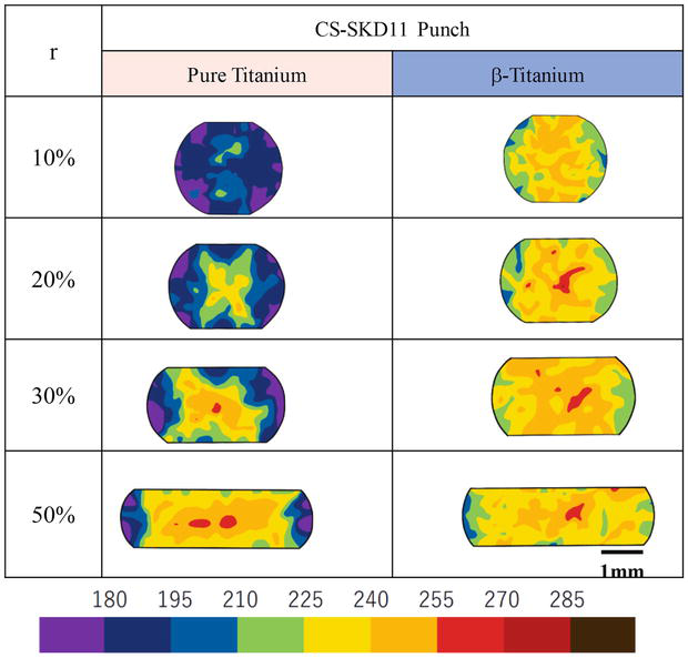
Figure 15.
Comparison of the micro-hardness mapping between the pure titanium and -phase titanium alloy bars, using the same CS-punch and CS-die.
The upsetting process is widely utilized in metal forming to imprint the die cavity shape to an upset work under free forging situation and to shape the pins onto the forged titanium products. Let us apply this CS-treatment to free forging punch and die. In practical upsetting process, the die is often shaped to form the initial round titanium bar to the deformed cross-sectional bar. In the conventional process without carbon supersaturation treatment, the shaping stage must be divided into several steps including the polishing and surface treatment with intermission. The CS-treatment is expected to save those tedious steps and to make near-net shaping from the round bar to the product in a single stroke. In the following experiment, the initial round bar with the diameter of 3.0 mm is free forged to the triangle cross-sectional bar within a single stroke.
The CS-punch and CS-die in Figure 16 were prepared for upsetting the round pure titanium bar to a triangular cross-sectional bar. Figure 17 describes the variation of bar shape with increasing r up to 45%. Through the swelling of work into the die cavity for r < 10%, the titanium work gradually fills into the whole die cavity with increasing r for r > 20%. Let us measure the load-stroke relationship at each reduction of thickness. After the initial swelling for r < 10%, the load gradually increases with contact interface area extension with r, as shown in Figure 18. This stable load-stroke relationship proves the monotonous filling of the swelled titanium bar into a die cavity to form the triangular cross-sectional bar.
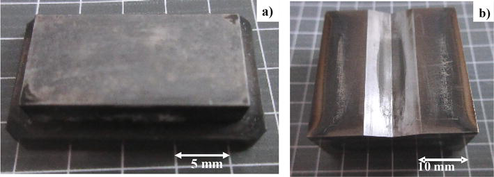
Figure 16.
CS-punch and CS-die for upsetting the round bar with the diameter of 3.0 mm to a triangular cross-sectional bar. a) CS-punch and b) CS-die.
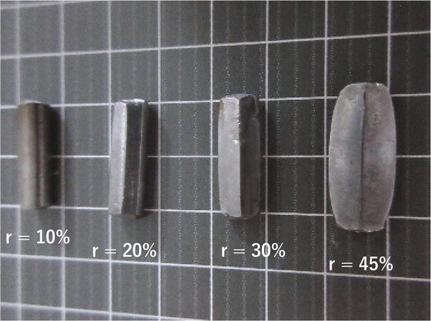
Figure 17.
Variation of the work shape with increasing the reduction of thickness (r) up to r = 45%.
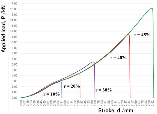
Figure 18.
Transients of the load-stroke relations with increasing r up to r = 45%.
Let us consider the role of CS-die on the filling process during shaping of the round β-phase titanium alloy bar to the triangular cross-sectional bar. HT (heat treatment) SKD11 die was used as a reference to analyze this role. The same CS-punch was used in both shaping processes. In both cases, no difference in the plastic strain distribution is noticed from the initial swelling step to the early stage of filling step into a die cavity in Figure 19. Toward the final stage of filling step, the uniform straining behavior is lost when using the HT-die, so that work hardening severely occurs at the vicinity of CS-punch surface and HT-die. On the other hand, the β-phase titanium work becomes free from this local work hardening and deforms with sufficient uniformity in straining when using the CS-die.
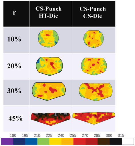
Figure 19.
Transients of the micro-hardness mapping in cross-section of β-phase alloy bars during the shaping process with and without the use of CS-die.
Finally, let us apply this pair of CS-punch and CS-die to continuous shaping of round β-titanium round bar to the triangular bar by shifting the CS-punch in every 20 mm. Figure 20 compares the initial round bar to the diameter of 3.0 mm with the continuously upset bar in four times. Within a single shot in each upsetting step, the initial round bar is successfully transformed to a long triangular bar. This demonstrates that a round β-titanium bar is used as a feedstock to deform any cross-sectional stringer and frame by the incremental shaping in tandem procedure.
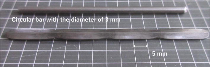
Figure 20.
An incremental shaping with r = 45% to continuously deform the round bar to a triangular cross-section bar by shifting the CS-punch in each 20 mm.
5. Titanium alloy pin forming by CS-die
The titanium eye-glass frame is made of various parts, which are forged and shaped all together in dry without lubrication [34]. A pin is a typical element to fix the interior component to titanium frame for high qualification of product. Due to the galling of titanium alloy to the dies in dry, this pin forming must be scheduled in multi-steps. Each unit step consists of the heat treatment and pickling, the anodizing and demold-coating and the upsetting. After this upsetting, the additional sub-steps are often necessary for trimming and barreling the burs. Toward high qualification of products, the first upset pin height has a significant influence on the final pin height with sufficient aspect ratio after multi-step operation.
In this titanium pin forming, the first upset pin height is employed as a parameter to describe the superiority of workability to the CS-dies. Tall pin height is preserved all through the pin-forming process. In particular, the intermediate steps and sub-steps are significantly saved by using the CS-die.
A type ACD56 tool steel with the hardness of HRC57 was prepared as a die for pin forming. A pure titanium bar with the diameter of 5 mm was used as a feedstock. A knuckle-joint stamper (AIDA160) was utilized for upsetting with the applied load of 1200 kN.
Figure 21 compares the first upset pin height by using the normal ACD56 die and CS-ACD56 die. The first upset pin height by the normal die is limited by 1.22 mm, less than the targeting height of 1.35 mm in schedule. On the other hand, the first upset height by CS-die reaches 1.68 mm, much taller than the targeting height. This difference proves that low friction and low adhesive wear are attained by using the CS-die just in the similar manner to the free forging process with the use of CS-punch and CS-die.
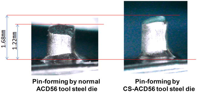
Figure 21.
Comparison of the first upset pin height by the normal and CS-ACD56 dies.
When using the normal die, its surface was adhered by the fresh titanium fragments. This galling increases the friction on the interface between the die and titanium work. If the applied load were kept constant, the upset height could decrease with increasing the number of strokes.
As expected in the above, the first upset ping height (h) gradually reduced with N when using the normal die; e.g., h = 1.22 mm at N = 1, h = 1.0 mm at N = 20 and h = 0.94 mm at N = 35. In addition to this reduction of pin height by galling, the deviation of h is also enhanced with increasing N, as depicted in Figure 22. On the other hand, h is nearly constant by h = 1.67 mm with less deviations even with increasing N. This high workability, with indifference to N, demonstrates that in situ formed free-carbon tribofilm significantly reduces the friction and adhesive wear on the contact interface.
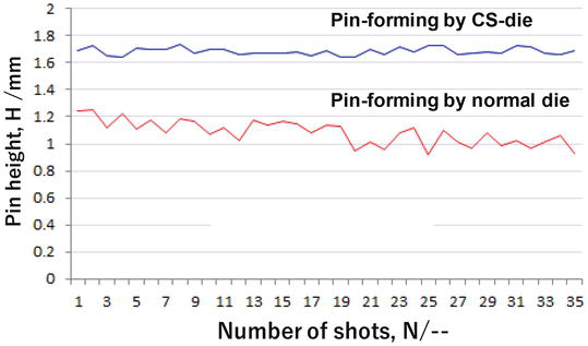
Figure 22.
Variation of the first upset pin height with increasing the number of strokes, using the normal and CS-dies.
The first upset pin height is preserved to be higher than the target level, so that the successive steps and sub-steps can be saved as pointed in Figure 23. In case that the target height is 3 mm, the first and second steps are enough to attain the high qualified products. In particular, the total processing cost might be significantly saved since many sub-steps for heat and surface treatments and surface polishing become unnecessary.
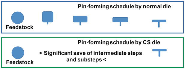
Figure 23.
Saving the intermediate steps in the pin forming when using the CS-dies.
In general, the forming procedure of titanium and titanium alloy bars to the final frame product consists of time-, energy-, labor- and cost-consuming processes. This reduction of steps and sub-steps in the pin-forming process enables a shortened processing time, reduced energy consumption and savings in labor cost in other parts of the forming schedule. In addition, the distance and gap between the designer’s product and the formed eye-grass frame can be much reduced, so that value of eye-glass frame products is much improved by manufacturing the designer’s model.
Figure 24 shows the revised pin-forming process with the near-net forging from the feedstock. Under the significant surface extension of work materials, low friction and wear state are preserved by using the CS-die.
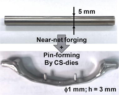
Figure 24.
New pin forming with near-net forging process in the procedure from the feedstock to the glass-frame preform.
6. Fine blanking of pure titanium plates by CS-dies
In the fine blanking, the metal, the polymer and their composite plates were sheared under the mechanical constraint to punch out the near-net-shaped parts with nearly full burnished surface [35]. As seen in Figure 7, various loads are also applied to fix the work plates between the dies and the work. Then, the ductile and active metals and alloys, such as the oxygen-free copper, the pure titanium and the stainless steels, are easy to adhere onto the punch and die surfaces [36].
Figure 25 shows a typical adhesion of debris fragments when fine blanking the pure titanium plate with the thickness of 2.0 mm even under lubrication. Since this galling occurs in a single-shot blanking, an innovative tooling to suppress the direct contact of fresh titanium work to dies is indispensable to continue the blanking process in the continuous production of the titanium parts. The CS-YXR7 (matrix type tool steel) punch and die are utilized to fabricate the pure titanium gears [37, 38]. The fine blanking stamper (FB-160FB; Mori Iron Works, Co., Ltd., Fukuoka, Japan) was employed to make continuous fine blanking experiments. The CS-YXR7 punch was machined and finished to have 12 teeth module-1.0 involute spur gear geometry after CAD-data with the pitch circle diameter of 12.00 mm, the pressure angle of 20°, the tip circle diameter of 14.00 mm, the tip radius of 0.3 mm, the root circle diameter of 10.00 mm and the root radius of 0.4 mm, respectively. These punch edges were accurately finished to have double chamfers for suppressing their abrasive wearing.
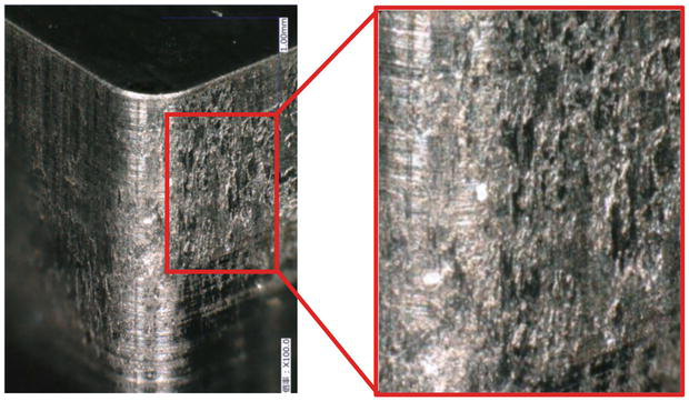
Figure 25.
Galling of pure titanium debris fragments onto the sheared surface of YXR7 punch with the square head.
Figure 26 depicts the sheared-out titanium gear blanks. Smooth gear surfaces are attained by using the CS-punch and die. This proves that severe adhesion of fresh titanium debris did not occur in this fine blanking process with the use of CS-YXR7 punch. How about the continuous fine blanking of pure titanium work? Figure 27 demonstrates that the series of titanium gears is yielded without severe damages to titanium blanks by galling. To be noticed, the gear-tooth surfaces of sheared blank at N = 1 have a fracture surface in partial. This partially fractured surface area fraction decreases with increasing N; the blanked gear-tooth surfaces are fully burnished at N = 50.

Figure 26.
The sheared-out pure titanium gear blank. Droops and burrs were slightly detected on the top and bottom blank surfaces, respectively.
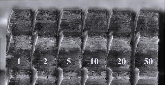
Figure 27.
Continuous fine blanking of pure titanium gears up to N = 50. The gear side surface condition was improved with increasing N.
Once the galling occurred on the punch to work interface at the initial or intermediate stages in this continuous fine blanking, the fractured surface area fraction could be gradually or steeply enhanced with increasing N. Figure 27 also reveals that the CS-punch to titanium work interface must be solid lubricated to reduce the fractured surface fraction by in situ formation of free-carbon tribofilm [39].
Let us investigate the surface conditions of tooth surface at the CS-YXR7 punch. Figure 28 compares the tooth edge profile of CS-YXR7 punch at the initial stage and after fine blanking up to 50 strokes. Very thin fragments with the thickness of clearance are seen on the tooth surfaces of CS-punch after shearing at N = 50. This punch was softly polished by the polymer brushes. Those thin fragments are cleaned and polished away, so that the surface condition of CS-YXR7 after brushing comes back to the initial condition, as compared in Figure 28. This proves that no galling takes place to induce the damages to the punch surfaces.
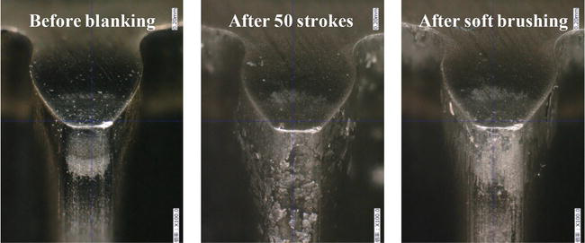
Figure 28.
Comparison of a gear-tooth profile before fine blanking, after fine blanking up to N = 50, and after softly brushing the used punch surface at N = 50.
Surface roughing process on the gear blanks is analyzed with increasing the number of strokes. Figure 29 depicts the variation of average surface roughness (Ra) with increasing N. Two positions were selected on the gear side surfaces at the 0 and 6 o’clock angles. Ra steeply increases from 1 to 2 μm up to N = 2. For N > 2, this roughness gradually decreases with N; e.g., Ra decreases from 2 μm at N = 2 to 0.6 μm at N = 50 at 0 o’clock angle. This initial steep increase corresponds to the occurrence of the fractured surface on the gear side surface as shown in Figure 27. The monotonous decrease of Ra with N is also in agreement with the gradual decrease of fracture surface area fraction with N. That is, the free-carbon tribofilm does not cover the whole contact interface to titanium work at N = 2, so that the fresh titanium fragments are taken away from work and deposited onto the CS-YXR7. This surface state change reflects on the surface roughing of blanks. With increasing the number of strokes, the free-carbon films agglomerate and cover the hot spots on the contact interface to be free from galling. Then, the burnished surface area fraction increases and the surface roughing is gradually suppressed to be less than the initial roughness level.
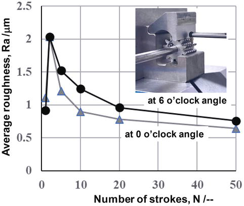
Figure 29.
Variation of the sheared gear-blank surface roughness at two positions with increasing the number of strokes.
7. Discussion
The galling or the adhesive wear becomes one of the most difficult issues to be overcome in the metal forming design. As reviewed in [40], four engineering items affect this problem in a complex way; i.e., the plastic strain, the surface condition, the flash temperature and the work material. This galling is classified into two categories: the mechanical galling and the mechano-chemical galling.
In the former issue, the friction and wear of tools and dies can be reduced by the surface treatment like ceramic coating or DLC coating [41], by the reduction of surface roughness [42], or by optimal selection of lubricants [43]. However, the latter issue is difficult or nearly impossible to be solved only by those methods. A typical mechano-chemical galling is experienced in forging, shaping and shearing the titanium and titanium alloy works. As reported in [43], the anodizing method played a role to make drawing and bending the titanium sheets without galling, even in MQL (Minimum Quantity Lubrication), since the contact area is limited to be narrow under a little application of plastic strains.
Severe mechano-chemical galling occurs in the forming of titanium alloy eye-glass flames, in the near-net forging of titanium feedstock to preforms or in the fine blanking of titanium plates to mechanical parts. The true contact interface between work materials and dies must be in situ lubricated in solid all through these processes. The massively carbon supersaturated (CS) tools and dies provide a non-traditional way to significantly reduce this type of galling in practical forming processes of titanium and titanium alloys.
In situ formation of free-carbon tribofilm onto the hot spots in the contact interface is common to every tribotesting and metal forming with the use of CS-disc, CS-punch and CS-die, respectively. The massively supersaturated carbon in the nano-structured layer is driven by the stress gradient to make jumping diffusion from one octahedral vacancy sites to the other through the nano-cluster boundaries, to isolate itself from the layer of CS-tool and to agglomerate on the hot spots [44]. Just in the similar manner in the nucleation and growth theory in materials science [45], an incubation time is necessary for the isolated free carbon to nucleate on the hot spots, to agglomerate itself to a solid dot and to form the free-carbon tribofilm on the contact interface. During this intermission, the titanium and titanium alloy work has a risk to adhere onto the CS-tool surface in partial.
In case of the tribotesting, the sticky increase of friction coefficient was observed at the initial stage in sliding movement of titanium ball onto CS-disc as seen in Figures 9 and 10. In the upsetting and free forging processes, the local adhesion of debris particles was seen on the hot spots as shown in Figure 12. At the beginning of the pin formation, a local adhesion of titanium alloys was detected in practical operations. The titanium adhesion was detected at the vicinity of CS-punch edge when fine blanking the pure titanium plates. This rate-effect on the local occurrence of adhesion could be saved by initially applying the stress gradients to the CS-tools before actual metal forming. During this learning step, the in situ solid lubrication process is activated in the CS-tools. Mechanical tapping [46] provides a way to form a thin free-carbon tribofilm onto the specified surface regions of CS-tool. Then, the tribofilm could work from the initial contact state to titanium and titanium alloy work materials.
The titanium alloy design stood on the optimum selection of chemical components to modify the original hcp-structured crystallography to bcc- or other structured system by phase transformation [47, 48, 49]. Although those studies were based on the uniaxial tensile or compressive experiments, the workability of designed titanium alloys was not evaluated properly under the multi-axial plastic straining. As studied in [50], the friction on the tool-work interface significantly affected the plastic strain localization and the ductile fracture in compression. The plastic strain gradient and local work hardening also have much influence on the workability of titanium alloys. Figures 15 and 19 demonstrate that low friction and low work hardening are sustained even at the high reduction of thickness, using the CS-punch and CS-die. Under this metal forming condition, the homogeneous plastic straining advances with active slipping systems of β-phase alloys. The superiority to β-phase alloy in plastic straining in the alloy design comes true only when using these CS-punches and CS-dies.
Let us consider the extension of this CS-die technology to the grain-size refinement and the forging of other work materials than titanium.
The grain size reduction with high crystallographic misorientations provides the simplest way to improve the strength of titanium and titanium alloys. Among various procedures for grain size refinement, the repeated forging process with the use of CS-dies becomes a suitable procedure to refine the original coarse grain size before near-net shaping.
The stress gradient to drive the isolation of carbon solute from nanostructure is induced by traction to the CS-tool surface during the elasto-plastic deformation of work materials. Then, the flow stress of work materials has influence on this applied traction to contact interface. When using the soft metals such as tin, lead or pure aluminum, this in situ solid lubrication has a risk not to be working, since the sufficient amount of free-carbon dots is not supplied from the CS-tools. In each material system, the initial learning process is needed to activate the in situ solid lubrication mechanism before actual forming. Almost all the stainless steels are in situ lubricated in solid without the initial learning step. When using AISI304 plates in fine blanking, the AISI304 gears are punched out without adhesive wear just as seen in Figures 26 and 27 [51]; much better burnished gear surface is attained by CS-punch and CS-die.
The light elements, such as boron (B), carbon (C), nitrogen (N) and oxygen (O), are possible to make massively supersaturation into various material systems, to significantly modify the initial microstructure of punch and die materials to nanostructures and to form a tribo-chemically synthesized surface layer. After the theoretical study on the supersaturation process [52], the nanostructuring with cluster formation is common to these massively interstitial solute supersaturation. The chemical activity is different in each species of interstitial solute. In the present study, the nanostructure of free-carbon film is synthesized from the diffusing carbon solutes through the nano-cluster boundaries. This chemical reaction on the contact interface of supersaturated dies to work materials is controlled by the chemical affinity between the interstitial solutes and the constituent elements of work materials.
8. Conclusion
The metal forming of titanium and titanium alloy parts, members and components for industries and medical markets has suffered from severe galling to dies by their debris fragments and particles. In particular, long forming steps with high labor cost and energy consumption hinder the way to advance the manufacturing process in their precise forging, net-shaping and fine blanking. The carbon supersaturation with high carbon solute content prevents these metal forming punches and dies from severe adhesions, so that the titanium and titanium alloy products are formed with high dimensional accuracy and with high surface finish.
The incremental dry forming of eye-glass titanium alloy frames required long series of steps including the additional sub-steps such as heat treatment, surface polishing and deburring. Five steps including these sub-steps are reduced to two steps without any sub-steps by using the CS-punch and die. This reduction of incremental forming steps and sub-steps significantly lowers the labor cost and energy consumption. The continuous mass production of titanium gears by fine blanking is free from intermission by adhesion of titanium work to punch and die. The lubricating oil consumption is much reduced to MQL level. Fully burnished gear surfaces are maintained through the whole production schedule.
In common to the above industrial applications, low friction on the contact interface results in the reduction of applied load. Low wearing state preserved through manufacturing proves high quality of product. Low work hardening assures the flexibility in near-net shaping and provides the way to complex shaping by precise forging. This advanced manufacturing by this carbon supersaturation technology must be essential in the sustainable society with circulation economy.
Except for the initial learning stage, the metal forming performance as well as the product quality are improved with increasing the number of strokes by using the CS-tools. This self-lubrication by the free-carbon tribofilm from CS-tools assures the longer tool life without change in the product quality. The incubation time for initial learning step is reduced by the mechanical tapping or by the learning trials. Since the isolation and diffusion of free-carbon solute from CS-dies to hot spots on the die-work interface are driven by the stress gradient, the formation of free-carbon tribofilm and its coverage onto hot spots is strongly dependent on the flow stress of work materials. BOD-testing and upsetting experiments are necessary to describe how effectively this in situ solid lubrication plays a role in each work-material system.
Massive carbon supersaturation via the low temperature plasma carburizing is further studied to deepen the CS-layer thickness in various die materials, to control the CS-layer distribution in depth and the hardness depth profile and to make plasma-printing with assistance of carbon solutes.
Acknowledgments
The authors would like to express their gratitude to S-I. Kurozumi (Nano-Coat Film, llc.), and S. Ishiguro (Graduate School of Engineering, Toyama University; now, PANASONIC, Co., Ltd.) for their help in experiments.
References
- 1.
Beal JD, Boyer R, Sanders D. Forming of titanium and titanium alloys. In: ASM Hand-Book 14B: Metal Working, Sheet Forming. Materials Park, OH, USA; 2006. pp. 656-669 - 2.
Hutchings I, Shipway P. Tribology: Friction and Wear of Engineering Materials. 2nd ed. New York, USA: Elsevier; 2017 - 3.
Kihara T. Visualization of deforming process of titanium and titanium alloy using high speed camera. In: Proc. 2019-JSTP Conference. Tokyo, Japan: JSTP; 2019. pp. 41-42 - 4.
Akbarzadeh M, Zandrahimi M, Moradpur-Tari E. Molybdenum disulfide coating on AISI316 stainless steel by thermo-diffusion method. Archives of Metallurgy and Materials. 2017; 62 :1741-1748 - 5.
Kataoka S, Murakawa M, Aizawa T, Ike H. Tribology of dry deep-drawing of various metal sheets with use of ceramic tools. Surface and Coating Technology. 2004; 178 :582-590 - 6.
Dohda K, Aizawa T. Tribo-characterization of silicon doped and nano-structured DLC coatings by metal forming simulators. Manufacturing Letters. 2014; 2 :82-85 - 7.
Dohda K, Yamamoto M, Hu C, Dubar L, Ehmann KF. Galling phenomena in metal forming. Friction. 2021; 9 :665-685 - 8.
Ahmed A, Li C. Lubrication and surface engineering. In: Principles of Engineering Tribology. Ch. 7 ed. Cambridge, MA, USA: Academic Press; 2023. pp. 295-343 - 9.
Aizawa T, Akhadejdamrong T, Mitsuo A. Self-lubrication of nitride ceramic coating by the chlorine ion implantation. Surface and Coating Technology. 2004; 178 :573-581 - 10.
Mitsuo A, Uchida S, Yamamoto S, Aizawa T. Improvement of cutting performance for carbide tools via chlorine ion implantation. Surface and Coating Technology. 2004; 189 :630-635 - 11.
Sumitomo T, Aizawa T, Yamamoto S. In-situ formation of self-lubricating tribofilm for dry machinability. Surface and Coating Technology. 2005; 200 :1797-1803 - 12.
Bachmann S, Schulze M, Krell L, Merz R, Wahl M, Stark RW. Ultra-low friction on tetrahedral amorphous diamond-like carbon (ta-C) lubricated with ethylene glycol. Lubricants. 2018; 6 (3):59-68 - 13.
Aizawa T, Itoh K-I, Fukuda T. SiC-coated SiC die for galling-free forging of pure titanium. Materials Transactions. 2020; 61 (2):282-288 - 14.
Aizawa T, Yoshino T, Suzuki Y, Shiratori T. Anti-galling cold dry forging of pure titanium by plasma carburized AISI420J2 dies. Journal of Applied Sciences. 2021; 11 (595):1-12 - 15.
Aizawa T, Yoshino T, Suzuki Y, Shiratori T. Free-forging of pure titanium with high reduction of thickness by plasma carburized SKD11 dies. Journal of Materials. 2021; 14 (2536):1-12 - 16.
Aizawa T, Yoshino T, Fukuda T, Shiratori T. Dry cold forging of pure titanium wire to thin plate with use of β-SiC coating dies. Journal of Materials. 2020; 13 (3780):1-11 - 17.
Aizawa T, Ito K-I, Fukuda T. Galling-free micro-forging of titanium wire with high reduction in thickness by β-SiC dies. Forming the future. The Minerals, Metals & Materials Society. Pittsburgh, PA, USA; 2021; 1 :1065-1075 - 18.
Aizawa T, Yoshino T, Shiratori T, Dohda K. Anti-galling β-SiC coating dies for fine cold forging of titanium. Journal of Physics: Conference Series. 2021; 1777 :012043 - 19.
Aizawa T. Micro-manufacturing by controlled plasma technologies. Automotive Tech. 2017; 72 (6):35-41 - 20.
Aizawa T, Funazuka T, Shiratori T. In situ lubrication in forging of pure titanium using carbon supersaturated die materials. Journal of Nanomaterials. 2024 (in press) - 21.
Aizawa T. Low temperature plasm nitriding of austenitic stainless steels. In: Stainless Steels and Alloys. Ch. 3 ed. London, UK, London: Intech Open, UK; 2019. pp. 31-50 - 22.
Aizawa T, Shiratori T, Yoshino T, Suzuki Y, Komatsu T. Nitrogen supersaturation of AISI316 base stainless steels at 673 K and 623 K for hardening and microstructure control. In: Stainless Steels. Ch. 4 ed. London, UK, London: Intech Open, UK; 2022. pp. 61-84 - 23.
Aizawa T. Micro−/meso-structure control of multi-hostmetal alloys by massive nitrogen supersaturation. Journal of Materials. 2024 (in press) - 24.
Ishiguro S, Aizawa T, Funazuka T, Shiratori T. Green forging of titanium and titanium alloys by using the carbon supersaturated SKD11 dies. Journal of Applied Mechanics. 2022; 3 :724-739 - 25.
Aizawa T, Ishiguro S, Shiratori T, Yoshino T. Near-net forging of titanium and titanium alloys by the plasma carburized SKD11 dies. Key Engineering Materials. 2022; 926 :1143-1150 - 26.
Aizawa T, Funazuka T, Shiratori T. Near-net forging of titanium and titanium alloys with low friction and low work hardening by using carbon-supersaturated SKD11 dies. Journal of Lubricants. 2022; 120 (203):1-15 - 27.
Suenaga R, Yunata E, Aizawa T. Quantitative plasma diagnosis of high- density RF-DC plasmas for surface processing. In: Proc. 7th SEATUC Conference (March 7th, 2013; Bandon, Indonesia). Yogyajarta, Indonesia: Gajamada University Press; 2013. pp. 63-68 - 28.
Rosadi I, Djoko D, Sakti SP, Yunata EE, Aizawa T. Plasma diagnosis on the mixture gas plasma state for nitriding process. In: Proc. 12th SEATUC Symposium, 2018, March 3rd. Yogyajarta, Indonesia: Gajamada University Press; pp. 131-136 - 29.
Aizawa T, Rasadi I, Yunata EE. High density RF-DC plasma nitriding under optimized conditions by plasma diagnosis. Applied Sciences. 2022; 12 (3716):1-12 - 30.
Ding Q , Wang L, Hu L. Tribology optimization by laser surface texturing: From bulk materials to surface coatings. In: Laser Surface Engineering; Processes and Applications. Ch. 16 ed. Witney, Oxford, UK: Woodhead Publishing; 2015. pp. 405-422 - 31.
Hong J-J, Yeh W-C. Application of response surface methodology to establish friction model of upset forging. Advances in Mechanical Engineering. 2018; 10 (3):1687814018766744 - 32.
Abdul Wasy Zia AW, Zhou ZF, Kwok-Yan LL. A preliminary wear studies of isolated carbon particles embedded diamond-like carbon coatings. Tribology Internatinal. 2017; 114 :42-47 - 33.
Yassin MA, Khairul SMS, Mahadzir I, Basim AK. Titanium and its alloys. International Journal of Scientific Research. 2014; 3 (10):1351-1361 - 34.
Tada H. Manufacturing technologies for titanium eyeglass frames. In: Titanium for Consumer Applications. Ch. 13 ed. New York, USA: Elsevier; 2019. pp. 235-268 - 35.
Feuerhack A, Trauth D, Mattfeld P, Klocke F. Fine Blanking of Helical Gears. 60 Excellent Inventions in Metal Forming. New York, USA: Elsevier; 2015. pp. 187-192 - 36.
Zheng Q , Zhuang X, Gao Z, Guan M, Ding Z, Hong Y, et al. Investigation on wear-induced edge passivation of fine-blanking punch. The International Journal of Advanced Manufacturing Technology. 2019; 104 :4129-4414 - 37.
Aizawa T, Fuchiwaki K, Dohda K. Galling-free fine blanking of titanium plates by carbon supersaturated tool-steel punch. Materials Research Proceedings. 2023; 28 :869-878 - 38.
Aizawa T, Fuchiwaki K. Galling-free fine blanking of titanium gears using the carbon-supersaturated YXR7 punch. In: Proc. 15th ICTP Conference. Cannes, France: LMNE; 17 Sep 2023. pp. 81-88 - 39.
Aizawa T, Fuchiwaki K. Galling-free fine blanking of titanium plates using carbon supersaturated high-speed steel punch. Journal of Carbon Research. 2023; 8 (15):1-12 - 40.
Kuniaki DK, Boher C, Rezai-Aria F, Mahayotsanun N. Tribology in metal forming at elevated temperatures. Friction. 2015; 3 (1):1-27 - 41.
Funazuka T, Dohda K, Mahayotsanun N. Applications of DLC coating to metal forming. In: Diamond like Carbon Coating: Technologies and Applications. Ch. 7 ed. Boca Raton, FL, USA: CRC Press; 2023. pp. 197-220 - 42.
Dubois A, Filali O, Dubar L. Effect of roughness, contact pressure and lubrication on the onset of galling of the 6082-aluminum alloy in cold forming, a numerical approach. Wear. 2024; 536-537 :205179 - 43.
Volz S, Launhardt J, Bay N, Hu C, Moreau P, Dubar L, et al. International round robin test of environmentally benign lubricants for cold forging. CIRP Annals. 2023; 72 (1):245-250 - 44.
Moskalioviene T, Galdikas A. Stress induced and concentration dependent diffusion of nitrogen in nitrided austenitic stainless steel. Computational Materials Science. 2012; 86 (10):1552-1557 - 45.
Wang F, Richards VN, Shields SP, Buhro WE. Kinetics and mechanisms of aggregative nanocrystal growth. Chemistry of Materials. 2014; 26 (1):5-21 - 46.
Wang L, Cao J, Zheng Y, Huang C, Wu S. The theoretical research on technical advance and innovation integration of tapping machinery. IOP Conference Series: Materials Science and Engineering. 2019; 592 :012068 - 47.
Zhao G-H, Liang XZ, Xu X, Gamża MB, Mao H, Louzguine-Luzgin DV, et al. Alloy design by tailoring phase stability in commercial Ti alloys. Materials Science and Engineering A. 2021; 805 :141229 - 48.
Pushp P, Dasharath SM, Arati C. Classification and applications of titanium and its alloys. Materials Today: Proceedings. 2022; 54 (2):537-542 - 49.
Zhang T, Liu C-T. Design of titanium alloys by additive manufacturing: A critical review. Advanced Powder Materials. 2022; 1 :100014 - 50.
Antolovich SD, Armstrong RW. Plastic strain localization in metals: Origins and consequences. Progress in Materials Science. 2014; 50 :1-160 - 51.
Aizawa T, Fuchiwaki K. Fine blanking of austenitic stainless steel gears by carbon-supersaturated high-speed steel tools. Machines. 2023; 11 (896):1-13 - 52.
Domain C, Becquart CS, Foct J. Ab initio study of foreign interstitial atom (C, N) interactions with intrinsic point defects in α-Fe. Physical Review B. 2004; 69 :144122