Open Access is an initiative that aims to make scientific research freely available to all. To date our community has made over 100 million downloads. It’s based on principles of collaboration, unobstructed discovery, and, most importantly, scientific progression. As PhD students, we found it difficult to access the research we needed, so we decided to create a new Open Access publisher that levels the playing field for scientists across the world. How? By making research easy to access, and puts the academic needs of the researchers before the business interests of publishers.
We are a community of more than 103,000 authors and editors from 3,291 institutions spanning 160 countries, including Nobel Prize winners and some of the world’s most-cited researchers. Publishing on IntechOpen allows authors to earn citations and find new collaborators, meaning more people see your work not only from your own field of study, but from other related fields too.
The concept of exergy, derived from the second law of thermodynamics, becomes a valuable source tool in analyzing thermal systems’ performance. Several terms encountered in the literature are synonymous or closely related to exergy, which are available energy, essergy, utilizable energy, and availability. The thermal efficiency of the power plants can be increased by adopting supercritical and ultra-supercritical conditions. Pressures exceeding 221.2 bar and steam temperatures exceeding 374.5°C are being used for supercritical thermal power plants, whereas the corresponding values for ultra-supercritical conditions are greater than or equal to 250 bar and 600°C. So, there is ample scope to enhance the steam conditions and optimize power plant configurations further to improve the plant efficiency. The power plant cycle is simulated by using Cycle Tempo version 5.0 software. It is used for advanced thermal energy system optimization. In the present work, for the thermodynamic analysis of supercritical—660 MW, and ultra-supercritical—800 MW power plant, cycle capacities are carried out and compared with subcritical power plant capacity of 500 MW. The important conclusions drawn from the current research work are the improvement in feed water temperature, optimum steam extraction pressures, and comparison of exergy efficiency of various thermal systems.
Lakireddy Bali Reddy College of Engineering, Mylavaram, Andhra Pradesh, India
Naradasu Ravi Kumar
MVGR College of Engineering, Vizianagaram, Andhra Pradesh, India
*Address all correspondence to: pasupuletirk@gmail.com
1. Introduction
Exergy was introduced by Z. Rant in 1956 [1]. It is preferred over energy analysis, because it cannot detect most thermodynamic imperfections, mainly irreversible heat transfer in system components. Exergy offers engineers a refined perspective on energy utilization. In the grand tapestry of engineering principles, the concept of exergy is grounded in understanding that not all energy is created equal [2]. Energy can exist in various forms—thermal, mechanical, chemical—but exergy takes a discerning approach, focusing on the energy that possesses the potential to perform work [3, 4].
Energy is a broad measure of the capacity to do work, while exergy narrows the focus to the portion of energy that can be converted into useful work. In simpler terms, energy is like a raw resource, and exergy is the refined, usable portion extracted for practical applications [5].
Exergy is a measure of the quality or usefulness of energy. It is only conserved when there are no irreversible processes in a system and its surroundings, which is never the case [6]. Exergy is always destroyed when irreversibility happens. By doing an exergy analysis on a plant like a power station, a chemical plant, nuclear or a cooling system, we can quantify the thermodynamic inefficiencies as exergy destructions and/or exergy losses, which indicate how much exergy is consumed (or depleted) in the system [7, 8, 9]. Exergy analysis considers the different thermodynamic values of different types of energy and amounts, such as work and heat. The exergy transfer with shaft work is the same as the shaft work. The exergy transfer with heat transfer, however, depends on how the temperature of the heat transfer compares to the temperature of the environment [10].
Traditional energy analyses, while informative, may fall short in pinpointing inefficiencies within a system. Exergy analysis, on the other hand, provides a more granular understanding of energy transformations, revealing the areas where exergy losses occur. Considering a steam power plant. Traditional energy analysis would highlight the overall energy input and output, offering insights into the plant’s efficiency. However, exergy analysis dives deeper, scrutinizing each component of the system. It identifies inefficiencies in the steam generator, turbine, and condenser, shedding light on specific areas where exergy losses occur [11]. Armed with this knowledge, engineers can implement targeted improvements, such as better insulation or more efficient turbines, to enhance the overall system efficiency. Some of the applications of exergy include:
Exergy analysis: This is a method of thermodynamic analysis that uses exergy as a basis for evaluating the performance and improvement potential of energy systems. Exergy analysis can identify the sources and causes of exergy destruction and loss and provide insights for enhancing the system design and operation [12, 13, 14, 15, 16].
Exergy optimization: This is a method of optimizing the design and operation of energy systems by minimizing the exergy destruction and loss or maximizing the exergy output or efficiency [17, 18]. Exergy optimization can be performed using mathematical models, numerical methods, or heuristic algorithms.
Exergy economics: This is a branch of thermoeconomics [19, 20] that uses exergy as a common currency for evaluating the cost and benefit of energy systems. Exergy economics can account for the quality and availability of energy resources, as well as the environmental impact of energy use.
Exergy sustainability: This is a concept that relates exergy to the sustainability of energy systems and human activities. Exergy sustainability can be defined as the ratio of exergy input to exergy output, or the ratio of exergy consumption to exergy production. Exergy sustainability can be used to measure the degree of compatibility between energy use and environmental preservation [21, 22, 23, 24].
The thermal power is the largest source of India. Coal and lignite [25] have accounted as 60% of India’s total installed capacity. India’s electricity sector consumption about 72% of the coal produced. In India, the total installation capacity of thermal power production has 207.77 GW. The coal-based power plants are based on the Rankine cycle. The main components of a cycle consist of steam generator, steam turbines, condenser, feed water heaters and several pumps. Power plant optimization can be done by any of the methods below.
Steam generator Optimization.
Condenser Pressure Reduction.
Reduction of steam generator pressure losses and leakages.
Minimization of combustion air excess.
Thermal losses minimization.
Improvement of steam generator efficiency & steam turbine components.
Main Steam Parameters Optimization.
Proper reheat pressure Optimization.
Feed water heater pressure optimization.
Steam turbine blade optimization.
3.1 Classification of power plant cycles
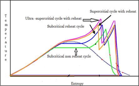
The power plants are classified into subcritical, supercritical, and ultra-supercritical, based on operating conditions and plant capacity. The classification of the coal fired power plants, and their steam parameters are summarized [26] shown in Table 1. The temperature-entropy plot presentation for subcritical, supercritical, and ultra supercritical cycle is mentioned in Figure 1.
Power plant cycle
Unit size (MW)
Main steam pressure (bar)
Main steam temperature (°C)
Reheat steam temperature (°C)
Subcritical
500
166
538
538
Supercritical
660
247
538
565
Ultra- supercritical
800
270
565
593
Table 1.
Classification of the coal fired power plants.
Figure 1.
Temperature – Entropy plane of three different power plant cycles [26].
3.2 Efficiency of the power plants
Thermal efficiency is very important to economic gain and it’s an important engineering effort over 250 years by applying various techniques and technologies implemented in thermal sector [27]. American Electric Power’s (AEP), Philo Plant Unit 6, steam generator is the first commercial supercritical unit, in service early in 1957. Philo 6th unit, a double reheat design, delivered 120 MW, operating at a steam flow rate of 85 kg/s, main steam pressure (MSP) 310 bar, MST/SRH/DRH 621/565°C and 538°C. The technology was supplied by the Babcock & Wilcox Company (B&W). In 1959, Philadelphia Electric Company’s Eddy stone, steam generator with a double reheat supplied by Combustion Engineering, Inc., delivered the net power output of 325 MW and the net plant thermal efficiency has 39.99% based on the higher heating value (HHV), at a flow rate of 252 kg/s under the main steam pressure of 345 bar, MST/SRH/DRH of 649/565°C and 565°C [28, 29, 30, 31, 32]. To investigate the efficiency of power plants by varying the steam parameters, authors have used various modern tools for simulation of power plant configurations are discussed in literature reviews are 1. Ebsilon, 2. Cycle Tempo, 3. IAPWS- Microsoft Excel 4. Gate Cycle, 5. Steam Pro, 6. Reference Prop 8.0 7. Engineering Equation Solver (EES), 8. MATLAB, 9. IPSE-PRO.
Mathematical formulations, pertaining to thermal power plant cycles are presented in terms of exergy analysis. The formulation of power plant processes is inherently non-convex, nonlinear by nature, which means that a good initial starting point and feasible bounds, for variables, must be provided to guarantee a good solution. To explore the benefits of steam parameters and structural changes in the process, it may be possible to build a general layout, containing all the possible process options and subjecting them to optimization. Therefore, it is essential to find a systematic way of building a general layout, which includes all the promising alternatives without being too large. The traditional way of designing power plants is to maximize the thermal efficiency of the plant [33].
4.1 Exergy analysis
Exergy is a property and is associated with the state of the system and the environment. It is not conserved. Once it is wasted, it can never be recovered. The useful work potential of a system is the amount of energy extracted as useful work. The useful work potential of a system at a specified state is called exergy. Exergy destruction or loss is proportional to the increase in entropy of the system together with its surroundings. The loss of exergy or irreversibility provides a quantitative measure of process inefficiency. Exergy efficiency does provide a measure of approach to ideality and exergy loss does provide measures of the deviation from ideality.
Exergy analysis [34, 35, 36, 37, 38, 39] is a powerful tool for evaluating the performance of energy conversion processes. It is based on the concept of exergy, which is the maximum amount of work that can be obtained from a system or a flow of matter and energy when it is brought into equilibrium with a reference environment. Exergy analysis allows us to identify the sources and causes of irreversibilities, losses, and inefficiencies in any process, and to quantify them in terms of exergy destruction. Exergy analysis can also help us to design more efficient and sustainable systems, and to optimize the use of available resources.
The exergy rate entering the system is equal to the sum of the exergy rate leaving the system plus the amount of exergy destruction rate during the process.
ΣExin=ΣExout+ΣExdestroyedE1
The calculation of exergy for different primary energy sources depends on the definition of the reference environment and the thermodynamic properties of the substances involved. For fossil fuels, such as coal, oil, and natural gas, the exergy is equal to their lower heating value, which is the amount of heat released when they are completely burned.
Exergy efficiency is a measure of how effectively a process converts exergy input into exergy output. It is defined as the ratio of exergy output to exergy input, multiplied by 100. Exergy efficiency can be used to compare different processes or systems that have different types and qualities of energy inputs and outputs. Exergy efficiency can also be used to assess the improvement potential of a process or system, by comparing it with an ideal or reversible process that has the same input and output conditions. Exergy efficiency is an important indicator of thermodynamic performance, environmental impact, and economic viability in various fields of industry. The different components of a power plant cycle and its exergy efficiency terms are mentioned below with mathematical equations.
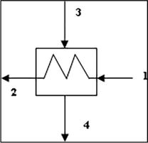
4.1.1 Steam generator
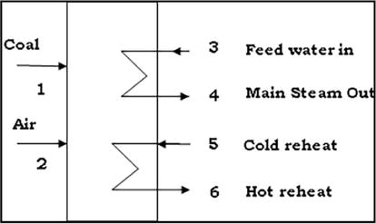
Steam generator is a closed vessel converts water into steam based on the pressure and temperature maintained in the generator by absorbing heat from the burnt coal [38]. The schematic diagram of steam generator shown in Figure 2.
Figure 2.
Schematic diagram of steam generator.
Exergy flow of streams for a steam generator can be calculated as.
ψ̇=ṁxh‐h0‐T0xs‐s0E2
Where, h and s represent the specific enthalpy and entropy of steam respectively, 0: dead state condition (atmospheric pressure and temperature).
In the exergetic performance analysis, exergy efficiency gives a measure of the performance of a system or a component.
Exergy absorbed in steam generator.
ψ̇SG=ṁxho‐hi‐T0xso‐siηSGE3
Exergy destruction or loss in steam generator can be calculated by
Where ψ̇destr,SG is the exergy destruction or loss in steam generator, ψ̇f is called exergy of fuel and it is always destroyed or consumed, whereas ψ̇p is called exergy of product and it is the amount of exergy which are produced.
Exergy efficiencyφSG=ψ̇4‐ψ̇3+ψ̇6‐ψ̇5/ψ̇1+ψ̇2E5
Where φSG: exergy efficiency in steam generator, ψ̇1: Exergy of coal, ψ̇2: Exergy of air, ψ̇3: feed water in, ψ̇5: Cold reheat or steam entering in to the reheater, ψ̇4: Main steam, ψ̇6: Hot reheat or superheated steam outlet from reheater.
4.1.2 Steam turbine
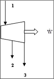
Steam turbine is driven with high pressure steam produced by a steam generator. It is a heat engine which converts the thermal energy of steam into mechanical work [40]. It is used to generate electricity by harnessing the power of steam in a power plant. The schematic diagram of steam turbine is shown in Figure 3.
Figure 3.
Schematic diagram of steam turbine.
Exergy destruction or loss in steam turbines shown in Figure 3 can be calculated by.
ψ̇destr,T=ψ̇1‐ψ̇2‐ψ̇3‐ẆE6
Where ψ̇1: Exergy of main steam flow in to steam turbine,
ψ̇2, ψ̇3: Steam extractions for feed water heating,
Ẇ: Work output from steam turbine.
Exergy efficiency of the steam turbine can be calculated by.
φT=Ẇψ̇1‐ψ̇2‐ψ̇3E7
4.1.3 Steam condenser
A steam condenser is a heat exchanger applied to convert low pressure exhaust steam from the steam turbine to water. The schematic diagram of steam condenser is shown in Figure 4.
Figure 4.
Schematic diagram of steam condenser.
Exergy destruction or loss in steam condenser shown in Figure 4 can be calculated as.
ψ̇destr,COND=ψ̇1+ψ̇3‐ψ̇2‐ψ̇4E8
Exergy efficiency in steam condenser can be calculated by Eq. (9)
φCOND=ψ̇4‐ψ̇3ψ̇1‐ψ̇2E9
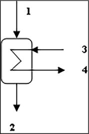
4.1.4 Feed water heater
A feedwater heater is a power plant component used to preheat water delivered to a steam generator. This process helps to improve the steam generator efficiency and reduces the fuel costs. The schematic diagram of feedwater is shown in Figure 5.
Figure 5.
Schematic diagram of one feed water heater.
Exergy destruction or loss in feed water heater shown in Figure 5 calculated as.
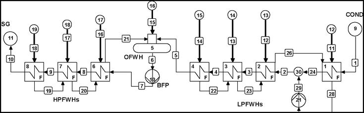
A power plant cycle consists of open feed water heaters (OFWH) called direct contact heat exchanger and closed feed water heaters called indirect contact heat exchanger. The closed feed water heaters are classified as low pressure closed feed water heaters (LPFWHs) and high-pressure feed water heaters (HPFWHs). The layout of different feed water heaters is shown in Figure 6. Part of steam is extracted from various steam turbines called low pressure, intermediate and high-pressure steam turbine to raise the condensed water temperature from steam condenser.
Figure 6.
Schematic layout of eight feed water heaters (LPFWHs and HPFWHs).
Exergy efficiency for high pressure feed water heaters φFWH calculated as
ψ̇10−ψ̇9ψ̇18−ψ̇19E14
HPFWH2=ψ̇9−ψ̇8ψ̇17+ψ̇19−ψ̇20E15
HPFWH1=ψ̇8−ψ̇7ψ̇16+ψ̇20−ψ̇21E16
For Open feed water heatersDEA=ψ̇6ψ̇15+ψ̇5+ψ̇21E17
Exergy efficiency φFWH for low pressure feed water heaters calculated as
LPFWH4=ψ̇5−ψ̇4ψ̇14−ψ̇22E18
LPFWH3=ψ̇4−ψ̇3ψ̇13+ψ̇22−ψ̇23E19
LPFWH2=ψ̇3−ψ̇2ψ̇12+ψ̇23−ψ̇26E20
LPFWH1=ψ̇24−ψ̇1ψ̇11+ψ̇26−ψ̇28E21
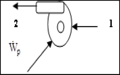
4.1.5 Feed water pump
Feed water pump is a power plant component used to pump the feed water coming from various feed water heaters into the steam generator and its schematic diagram is shown in Figure 7.
Exergy destruction or loss in pumpψ̇destr,P=ψ̇1‐ψ̇2+ẆpE22
Exergy efficiency in pumpφP=ψ̇2‐ψ̇1ẆpE23
Figure 7.
Schematic diagram of feed water pump.
Total exergy destruction or loss in the plant can be determined as sum of exergy destruction rates of components:
For the whole thermal power plant, the exergy efficiency can be given.
φ=ẆnetṁcoalxψcoalE25
Where ψcoal: specific exergy of coal, ṁcoal: Mass of the coal.
Ẇnet: Network output from turbines.
4.2 Quasi-Newton optimization
The process to get maximum thermal efficiency of a cycle describes the optimization steps in Cycle Tempo. Quasi-Newton optimization technique in Cycle Tempo 5.0 is recognized today as one of the most powerful tools for feeding steam extraction pressures optimization from steam turbines. It usually converges fast, and sometimes converges even without step length control. In the initial step, give the input values to the components presented in the cycle diagram. In the second step, start with initial guess values by giving starting steam extraction pressures from turbines Xi, Let i = 1. In the third step, it calculates the mass & energy balance equations. In the fourth step, it computes the objective function f(Xi) as η of thermal power plant cycle. In the fifth step, it generates a new solution Xi + 1 as steam extraction pressures from the turbines. In the sixth step, it computes the objective function f (Xi + 1) as thermal efficiency (η) of power plant. In the seventh step, it checks for convergence on efficiency of plant. In the eighth step, it will check for maximum efficiency of a plant. In the ninth step, if it is ok that gives the message as success and updates the geometry as an optimal solution.
The simulation and optimization of three different thermal power plant cycles are carried out, with Cycle Tempo 5.0 simulation software tool for energy systems. The following parameters have been studied for 500, 660 and 800 MW power plant cycles. The performance of the power plant cycle configuration is mentioned in Tables 2–6 and shown in Figures 8–12. In the current study exergy analysis was used as a tool to identify the thermodynamic losses and exergy efficiencies in various components of the power plant cycle with the help of Cycle Tempo 5.0. [41].
MSP (bar)
Net thermal and exergy efficiency (%)
500°C
600°C
700°C
200
41.33
38.96
42.30
39.88
43.59
41.09
220
41.49
39.11
42.85
40.39
44.09
41.56
240
41.60
39.21
43.03
40.56
44.29
41.75
260
41.67
39.28
43.16
40.69
44.47
41.92
280
41.71
39.32
43.27
40.79
44.62
42.06
300
41.70
39.31
43.33
40.86
44.79
42.13
Table 2.
Net thermal and exergy efficiency of plant (%) at different main steam temperatures and pressures.
Main steam pressure (bar)
Main steam temperature
500°C
600°C
700°C
200
752.54
677.73
603.51
250
810.35
696.86
614.06
300
847.91
718.93
631.77
Table 3.
Variation of steam consumption (kg/s) at different main steam pressures and temperatures.
Main steam pressure (bar)
Main steam temperature
500°C
600°C
700°C
200
453
443
430
250
452
438
422
300
450
433
418
Table 4.
Variation of coal consumption in tonnes per hour at different main steam pressures and temperatures.
MST
Subcritical
Supercritical
Ultra-supercritical
Auxiliary power consumption (MW)
500°C
6.65
8.77
10.64
600°C
6.17
8.12
9.54
700°C
5.75
7.84
8.75
Table 5.
Comparative auxiliary power consumption in three different power plant cycles.
Feed water heaters
Subcritical
Supercritical
Ultra-supercritical
Steam extraction pressures (bar)
LPFHW1
0.32
0.34
0.36
LPFWH2
0.87
0.96
0.98
LPFWH3
1.96
2.26
2.50
LPFWH4
4.04
4.78
5.78
DEA(OFWH)
7.96
9.59
12.01
HPFWH1
14.62
18.35
23.34
HPFWH2
31.21
39.80
48.94
HPFWH3
75.61
92.31
107.58
Feed Water temperature (°C)
290.65
304.40
315.34
Table 6.
Comparison of steam extraction pressure (bar) optimization in three different power plant cycles.
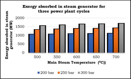
Figure 8.
Exergy absorbed in steam generator for three power plant cycles.
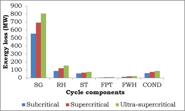
Figure 9.
Exergy loss of different components in three different power plants.
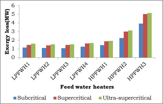
Figure 10.
Exergy loss in closed feed water heaters of three different power plant cycles.
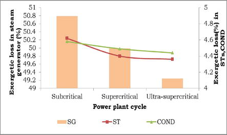
Figure 11.
Exergetic loss variations of different components of three different power plant cycles.
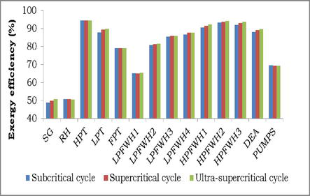
Figure 12.
Variation of exergy efficiency of power plant components in three different power plant cycles.
The key output parameters which can be observed to see for changed input parameters are exergy absorbed in steam generator and reheater, Exergy loss/Total exergy input in steam generator, reheater and steam turbines, Exergy loss in different components, Exergy loss and rate of heat transfer in closed regenerative feed water heaters, Thermal and exergy efficiency, Impact of condenser pressure variation on exergy efficiency, Auxiliary power consumption and pipe exergy losses, Coal, and steam consumption. All these parameters are based on steam extraction pressure optimization from feed water heaters to get maximum plant cycle efficiency.
Efficiency of the Rankine cycle can be improved by increasing the average temperature of heat addition or by decreasing the average temperature of heat rejection [42].
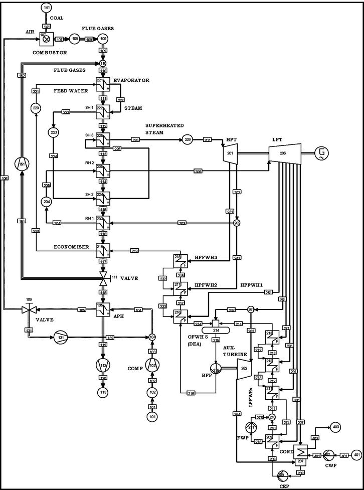
In thermal power plants, the average heat addition is increased, by setting number of feed water heaters. The feed water enters the steam generator (Evaporator), through economizer. The performance of a power plant is characterized by its power output, efficiency, heat rate, steam rate, fuel rate, etc., In the present work, the efficiency of thermal power plant cycles (subcritical, supercritical and ultra-supercritical) is analyzed by considering, the key input parameters of, main steam pressure (MSP), main steam temperature (MST), reheat temperature and condenser pressure, etc., Figure 13 shows, the schematic layout of thermal power plant, contains combustor (air + coal) releases the flue gases and passes through the various heat exchangers like (evaporator, superheaters), where feed water gets converted to steam according to the steam parameters maintained in a power plant cycle called as steam generator (SG). The steam and then passes into the high-pressure turbine (HPT), reheater to low pressure turbine (LPT), condenser (COND), four closed feed water heaters (four low pressure feed water heaters (LPFWHs) and three high pressure feed water heaters (HPFWHs)), one open feed water heater (OFWH) called as deaerator (DEA) called feed water heater section and various pumps (Boiler feed pump, water pumps). The feed water from feed water heater section into the economizer and then passes into the evaporator, where it gets converted into steam based on steam parameters.
Figure 13.
Process flow sheet layout of thermal power plant cycle [41].
The assumptions considered for the thermal power plant cycle shown in Figure 13 are available in Table 7. Before the analysis, any power plant components should be given some assumptions to evaluate the performance of the system.
Table 2 shows the effect of main steam pressure on thermal and exergy efficiency of a plant cycle. It shows that the exergy efficiency of a cycle is less than thermal efficiency of cycle and this is due to chemical exergy of coal is greater than the calorific value of coal. As the main steam pressure is raised, the thermal efficiency increases up to a pressure of 280 bar for subcritical power plant cycle and there after it decreases. This shows that the optimum limit of efficiency increases. After 280 bar, the efficiency decreases due to less work output from the turbines and increase of pump work.
Variation of steam consumption (kg/s) at different main steam pressures and temperatures are shown in Table 3. It shows the steam consumption increases when the main steam pressure is raised due to reduced enthalpy of steam. Steam consumption decreases when the main steam temperature is raised at a particular pressure of 200 bar due to high enthalpy of steam. To meet the required power plant capacity of 500MW with high enthalpy steam content can reduce steam consumption.
The coal consumption in tonnes per hour (TPH) for a power plant operating at different steam conditions is shown in Table 4. It shows that coal consumption decreases, both with the increase of main steam pressures and temperatures. But the decrease of coal consumption is little bit less when main steam pressure is raised as compared to the different main steam temperatures.
The comparison of auxiliary power consumption results is shown in Table 5. The auxiliary power consumption decreases, as the main steam temperatures have increased from 500–700°C. The auxiliary power consumption decreases to all the power plant cycles, because it depends on the specific volume of steam and quality of steam entering pumps when the main steam temperature is raised. The cooling water required by the condenser also decreases when main steam temperatures are raised. Auxiliary power consumption increases, with the increase of the power plant capacity.
The percentage of auxiliary power consumption has increased 24%, compared to subcritical plant, whereas the same value is increased to 14.8%, compared to supercritical power plant cycle. But overall, 35% auxiliary power consumption is increased compared to subcritical power plant cycle.
The comparison of steam extraction pressure optimization of 8 regenerative feed water heater stages and feed water temperatures, in the power plant cycles are shown in Table 6. It shows that the optimum steam extraction pressures and feed water temperatures are increased. This is due to the increase in steam flow rate. The feed water temperature improvement is 4.51%, compared to subcritical steam power plant cycle, 3.47% compared to supercritical power plant cycle and overall, 7.82% compared to subcritical power plant cycle.
The variation of exergy absorbed in steam generator is shown in Figure 8. It shows the exergy absorbed in steam generator increases gradually, as the main steam temperature is raised. This is due to the increase in entropy of steam.
Exergy is how much work output is possible to convert on using heat content of steam. But overall, the exergy absorbed both in steam generator and reheater decreases due to constant reheat temperature. The exergy absorbed in steam generator is 21.47% compared to subcritical power plant, 15.46% compared to supercritical, and overall, the exergy absorbed in steam generator is 33.62% between ultra-supercritical to subcritical cycle at a main steam temperature of 600°C.
The exergy loss, measured in megawatt (MW) of different plant cycle components, for three different power plants capacity are shown in Figure 9. It shows the exergy loss increases to all components. The major exergy loss found in steam generator but in reheater, steam turbine and in condenser it decreases. When the power plant capacity rises the difference in exergy loss increases. The difference in exergy loss in terms of percentage increases in steam generator between subcritical and supercritical up to 19.87%. Whereas the same value in between the supercritical and ultra-supercritical is 41.10%. The overall difference in exergy loss is 31.17% between the subcritical and ultra-supercritical. The difference in exergy loss in percentage is increased in reheater between subcritical and supercritical is 27.10% whereas the same value in between the supercritical and ultra-supercritical is 21.67%. The overall difference in percentage exergy loss between the subcritical and ultra-supercritical is 42.90%.
The difference in exergy loss in percentage is increased in feed pump turbine between subcritical and supercritical is 40.70% whereas the same value in between the supercritical and ultra-supercritical is 33.36%. The overall difference in percentage exergy loss between the subcritical and ultra-supercritical is 60.48%. The difference in exergy loss in terms of percentage found less in feed water heater and then in condenser.
The exergy loss in feed water heaters is up to 8 regenerative stages which are shown in Figure 10. As the number of feed water heaters increases the exergy loss decreases. The difference in exergy loss percentage is increased in regenerative feed water heaters between subcritical and supercritical is 22.92%. The same value between the supercritical and ultra-supercritical is 4.47%. The overall difference in exergy loss (%) between the sub and ultra-supercritical is 26.37%.
The percentage exergetic loss in steam generator, steam turbines and condenser decrease from subcritical to ultra-supercritical power plant cycles shown in Figure 11. The major percentage exergetic loss occurs in steam generator and its value in subcritical state is 50.79% and the same value in supercritical state is 49.99%. It shows the percentage of exergetic loss decreases in between subcritical to supercritical is 1.60% and the same in between supercritical and ultra-supercritical is only 1.52%.
The overall percentage difference between ultra-supercritical and subcritical is 3.14%. The exergetic loss also decreases in steam turbines and in condenser. But the overall reduction in percentage is very small.
The exergy efficiency of individual components like steam generator, reheater, different turbines, feed water heaters and pumps are shown in Figure 12. It shows the exergy efficiency increases in all the components except feed pump. The energy efficiency of steam generator and reheater lie in the range of 48 to 51%. HPT and HPFWHs show the high exergy efficiency in the range of 90 to 95%. LPT and LPFWHs show the exergy efficiency in the range of 80 to 90% and feed pump shows the exergy efficiency in the range of 65 to 70%. Only the feed pump turbine has constant exergy efficiency in all power plant cycles. The power producing device shows more exergy efficiency. The feed water heaters have more exergy efficiency because of the heat transfer between steam and feed water. In deaerators the exergy efficiency decreases as the main steam temperature have raised. But when main steam pressure is raised, the exergy efficiency of deaerator increases.
From the aforementioned information in tables and figures, the following conclusions may be drawn as
As the main steam temperature is raised by keeping reheat temperature as constant the optimum steam extraction pressure values for 8 regenerative stages decreases.
Auxiliary power consumption decreases as the main steam temperature is raised for a main steam pressure to all power plant capacities.
The energy and exergy absorbed in steam generator increases to three power plant capacities.
Exergy loss in steam generator decreases from subcritical power plant cycle to ultra-supercritical power plant cycle.
Comparing the rates of heat transfer in feed water heaters from subcritical to ultra-supercritical power plant cycle, more heat transfer is possible between subcritical to supercritical compared to supercritical and ultra-supercritical steam conditions.
The exergy efficiency of a steam generator increases as the main steam input parameters are raised.
The feed water temperature of a plant can be improved by raising the steam input pressures.
The exergy analysis reveals that the subcritical units are less efficient to utilize the available exergy of coal compared with supercritical and ultra-supercritical units.
Specific steam and coal consumption decreases when higher steam input parameters are used.
Simulation and exergy analysis are useful in system optimization. They not only indicate the direction of system optimization, but also provide a theoretical basis for the system optimization.
The average cooling water requirement in condenser/MW for subcritical plant capacity of 500 MW is 40 kg/s, for supercritical 660 MW, it is 38 kg/s and for ultra-supercritical 800 MW capacity, it is 37 kg/s.
The authors would like to thank the ASIMPTOTE – Cycle Tempo 5.0 licensed software, Delft University of technology, Netherlands for carrying out the exergy analysis of thermal power plants in the year 2016–2017.
1.Moran MJ, Shapiro HN. Fundamentals of Engineering Thermodynamics. 3rd ed. New York: John Wiley & Sons; 1996
2.Cengel YA, Boles MA. Thermodynamics: An Engineering Approach. 5th ed. Boston: McGraw-Hill; 2006
3.Khartchenko NV, Kharchenko VM. Advanced Energy Systems. 2nd ed. Boca Raton, London, Newyork: CRC Press, Taylor & Francis group; 2013. p. 97. Availbale from: https://books.google.com/books/about/Advanced_Energy_Systems_Second_Edition.html?id=BSAtAgAAQBAJ
4.Sonntag R, Borgnakke C, Van Wylen GJ. Fundamentals of Thermodynamics. 6th Wiley student ed. University of Michigan: John Wiley and Sons Inc.; 2003. pp. 302-363. Availbale from: https://bcs.wiley.com/he-bcs/Books?action=index& bcsId=1252& itemId=0471152323. ISBN: 0-471-15232-3
5.Kanoglu M, Dincer I, Rosen MA. Understanding energy and exergy efficiencies for improved energy management in power plants. Energy Policy. 2007;35:3967-3978. DOI: 10.1016/j.enpol.2007.01.015
6.Bejan A. Fundamentals of exergy analysis, entropy generation minimization, and the generation of flow architecture. International Journal of Energy Research. 2002;26(7):545-565. DOI: 10.1002/er.804
7.Rosen MA. Clarifying thermodynamic efficiencies and losses via exergy. International Journal of Exergy. 2002;2:3-5. DOI: 10.1016/S1164-0235(02)00055-9
8.Dincer I. The role of exergy in energy policy making. Energy Policy. 2002;30(2):137-149. DOI: 10.1016/S0301-4215(01)00079-9
9.Rosen MA. Energy- and exergy-based comparison of coal-fired and nuclear steam power plants. Exergy. 2001;1(3):180-192. DOI: 10.1016/S1164-0235(01)00024-3
10.Rosen M, Dincer I. Effect of varying dead-state properties on energy and exergy analyses of thermal systems. International Journal of Thermal Sciences. 2004;43:121-133. DOI: 10.1016/j.ijthermalsci.2003.05.004
11.Tsatsaronis G, Cziesla F. Basic exergy concepts, exergy balance and exergetic efficiency, exergy analysis of simple processes, energetic and exergetic analysis of complex systems, strength and limitations of exergy analysis. In: Encyclopedia of Life Support Systems (EOLSS), Topic Energy, Developed under the Auspices of the UNESCO. Oxford, UK: EOLSS Publishers; 2004. Available from: http://www.eolss.net
12.Horlock JH et al. Exergy analysis of modern fossil-fuel power plants. ASME Journal of Engineering for Gas Turbines and Power. 2000;122:1-7. DOI: 10.1115/1.483170
13.Aljundi IH. Energy and exergy analysis of a steam power Plant in Jordan. Applied Thermal Engineering. 2009;29(2–3):324-328. DOI: 10.1016/j.applthermaleng.2008.02.029
14.Gupta MK, Kaushik SC. Exergy analysis and investigation for various feed water heaters of direct steam generation solar – Thermal power plant. Renewable Energy. 2010;35:1228-1235. DOI: 10.1016/j.renene.2009.09.007
15.Amirabedin E, Zeki Yilmazoglu M. Design and exergy analysis of a thermal power plant using different types of Turkish lignite. International Journal of Thermodynamics (IJoT). 2011;14(3):125-133. DOI: 10.5541/ijot.288
16.Suresh MVJJ, Reddy KS, Kolar AK. 3-E analysis of advanced power plants based on high ash coal. International Journal of Energy Research. 2010;34:716-735. DOI: 10.1177/0957650911418421
17.Sanpasertparnich T, Aroonwilas A. Simulation and optimization of coal-fired power plants. Energy Procedia. 2009;1(1):3851-3858. DOI: 10.1016/j.egypro.2009.02.187
18.Witold E, Łukasz K, Maciej M. Numerical thermodynamic optimization of supercritical coal fired power plant with support of IPSEpro software. Archives of Thermodynamics. 2012;33(3):101-110 Available from: https://bibliotekanauki.pl/articles/240118.pdf
19.Saidur R, Ahamed JU, Masjuki HH. Energy exergy and economic analysis of industrial boilers. Energy Policy. 2010;38:2188-2197. DOI: 10.1016/j.enpol.2009.11.087
20.Wang L, Yang Y, Changqing D, Yang Z, Xu G, Wu L. Exergo-economic evaluation of a modern ultra-supercritical power plant. Energies. 2012;5(6):3381-3397. DOI: 10.3390/en5093381
21.Kosowski K et al. Steam and Gas Turbines with Examples of Alstom Technology. 2nd ed. Three parts in one volume. Alstom, France, Switzerland, United Kingdom, Poland; 2007
22.Kuprianov VI. Applications of a cost-based method of excess air optimization for the improvement of thermal efficiency and environmental performance of steam boilers. Renewable and Sustainable Energy Reviews. 2005;9:474-498. DOI: 10.1016/j.rser.2004.05.006
23.Singh OK, Kaushik SC. Variables influencing the exergy-based performance of a steam power plant. International Journal of Green Energy 2013;10(3):257-284. DOI: 10.1080/15435075.2011.653847
24.Siva RV, Kaushik SC, Tyagi SK. Exergetic analysis and evaluation of coal fired supercritical thermal power plant and natural gas fired combined cycle power plant. Clean Technology Environmental Policy. 2013;15:1-11. DOI: 10.1007/s10098-013-0647-x
25.Ganapathy T, Alagumurthi N, Gakkhar RP, Murugesan K. Exergy analysis of operating lignite fired thermal power plant. Journal of Engineering Science and Technology Review. 2009;2(1):123-130. DOI: 10.25103/jestr.021.23
26.Anto B, Hasan MM. Analysis of Supercritical technology in Indian Environment and Utilizing Indian coal. 2010. pp 1-163. Availbale from: https://www.scribd.com/doc/20902219/Paper-on-Super-Critical-Technology-and-Analysis-for-Indian-Environment
27.Srinivas T, Gupta AVSSKS, Reddy BV. Generalized thermodynamic analysis of steam power cycles with ‘n’ number of feed water heaters. International Journal of Thermodynamics. 2007;10(4):177-185. DOI: 10.5541/ijot.201
28.Weizhong F. 1000MW ultra-supercritical turbine steam parameter optimization. Frontiers of Energy and Power Engineering in China. 2008;2(2):187-193. DOI: 10.1007/s11708-008-0030-5
29.Yanjun F, Wang Z. Mathematical modelling and dynamic simulation of intermediate point temperature for ultra-supercritical once-through boiler II. In: IEEE Transaction 2012, The 6th International Conference on Soft Computing and Intelligent Systems, and The 13th International Symposium on Advanced Intelligence Systems. Vol. 2. 2012. pp. 922-927. DOI: 10.1109/SCIS-ISIS.2012.6505267
30.Zhou L, Gang X, Cheng X, Yongping Y, Li Y, Jianling D. Optimum design of a double reheat steam system in an ultra-supercritical unit. In: Proceedings of ASME Turbo Expo 2013: Turbine Technical Conference and Exposition, June 3-7. Vol. 5(B). San Antonio, Texas, USA; 2013. pp. 1-11. DOI: 10.1115/GT2013-95190. ISBN: 978-0-7918-5520-1
31.Yongping Y, Ligang W, Changqing D, Xu G, Morosuk T. Comprehensive exergy-based evaluation and parametric study of a coal fired ultra-supercritical power plant. Applied Energy. 2013;112:1087-1099. DOI: 10.1016/j.apenergy.2012.12.063
32.Li Y, Luyao Z, Gang X, Yaxiong F, Shifei Z, Yongping Y. Thermodynamic analysis and optimization of a double reheat system in an ultra-supercritical power plant. Energy. 2014;74:202-214. DOI: 10.1016/j.energy.2014.05.057
33.Carl KF. Modeling, Analysis and Optimization of Process and Energy systems, Louisiana State University Baton Rouge, LAA: John Wiley & Sons, Inc.; 2012. pp. 397-417. Availbale from: https://onlinelibrary.wiley.com/doi/book/10.1002/9781118121160
34.Li Z, Li Z, Yan Z. Energy and exergy analysis for three type 500MW steam power plants. Applied Mechanics and Materials. 2012;148–149:1131-1136 Available from: www.scientific.net
35.Erdem H, Akkaya AV, Dagdas A, Sevilgen SH, Sahin B, Tek I, et al. Comparative energetic and exergetic performance analyses for coal-fired thermal power plants in Turkey. International Journal of Thermal Sciences. 2012;48(11):2179-2186. DOI: 10.1016/j.ijthermalsci.2009.03.007
36.Mitrovic D, Zivkovic D, Lakovic MS. Energy and Exergy Analysis of 348.5 MW Steam Power Plant. Vol. 32. Part A. Taylor & Francis; 2010. pp.1016-1027. DOI: 10.1080/15567030903097012
37.Kelly S, Tsatsaronis Η, Morosuk T. Advanced exergetic analysis: Approaches for splitting the exergy destruction into endogenous and exogenous parts. Energy. 2009;34(3):384-391. DOI: 10.1515/tjj-2016-0074
38.Regulagadda P, Dincer I, Naterer GF. Exergy analysis of a thermal power plant with measured boiler and turbine losses. Applied Thermal Engineering. 2010;30:970-976. DOI: 10.1016/j.applthermaleng.2010.01.008
39.Sandhya H, Aroonwilas A, Veawab A. Exergy analysis of Ultra-supercritical power plant. Energy Procedia. 2013;37:2544-2551. DOI: 10.1016/j.egypro.2013.06.137
40.Leizerovich AS. Steam Turbines for Modern Fossil-fuel Power Plants. 1st ed. New York: River Publishers; 2008. DOI: 10.1201/9781003151388
41.Asimptote bv.De Schans 23; 5473 PH Heeswijk-Dinther; The Netherlands. Available from: https://asimptote.com/cycle-tempo/
42.Madejski P. Introductory Chapter: New Trends and Recent Developments for Thermal Power. InTechOpen; 2018. DOI: 10.5772/intechopen.74723. Available from: https://www.intechopen.com/chapters/59649
Written By
Pasupuleti Ravindra Kumar and Naradasu Ravi Kumar
Submitted: 30 January 2024Reviewed: 04 February 2024Published: 24 April 2024