Open Access is an initiative that aims to make scientific research freely available to all. To date our community has made over 100 million downloads. It’s based on principles of collaboration, unobstructed discovery, and, most importantly, scientific progression. As PhD students, we found it difficult to access the research we needed, so we decided to create a new Open Access publisher that levels the playing field for scientists across the world. How? By making research easy to access, and puts the academic needs of the researchers before the business interests of publishers.
We are a community of more than 103,000 authors and editors from 3,291 institutions spanning 160 countries, including Nobel Prize winners and some of the world’s most-cited researchers. Publishing on IntechOpen allows authors to earn citations and find new collaborators, meaning more people see your work not only from your own field of study, but from other related fields too.
High-speed UAV flight control is challenged by unknown external aerodynamic disturbances and internal system variations due to complex aerodynamic configuration, propellant consumption, the center of gravity movement, and possible actuator failures. Redundant aerodynamic control effectors and engine inlet control mechanisms are exploited/blended to maintain adequate force/moment control to satisfy flight control reliability requirements. A control allocation (CA) mixing matrix is an essential element of the redundancy design in addressing fault tolerance capabilities. This paper employs an Intelligent Flight Controller (IFC) implemented in an adaptive control augmentation fashion to assist the UAV’s primary Nonlinear Dynamic Inversion (NDI) controller in restoring aircraft stability and command following objective when subjected to effector performance degradation, including failures. Through a blended design between optimal control modification (OCM) and derivative-free model reference adaptive control (DF-MRAC), the IFC offers performance consistency in comparison to traditional MRAC. The proposed IFC framework has demonstrated its effectiveness in assisting the baseline NDI flight control system to maintain its mission subjected to actuator’s failures (via an implicit automatic CA ‘re-distributing’ action). Furthermore, the IFC also works well with any existing onboard CA algorithm in dealing with effector failures without requiring restructuring of the CA blending matrix. It therefore deserves consideration for application to future high Mach UAVs.
Keywords
nonlinear dynamic inversion (NDI)
control allocation (CA)
optimal control modification (OCM)
derivative-free model reference adaptive control (DF-MRAC)
*Address all correspondence to: quang.lam@jesplsoft.com
1. Introduction
Flight control systems (FCSs) are one of the most important safety-critical systems in modern aircraft and high-speed UAVs. Redundancy of both FCS software (FSW) and its associated actuators/effectors (aerodynamic control surfaces and engine inlet control mechanisms) are exploited to achieve robust performance and high reliability against component failures (hardware and/or software redundancy, e.g., see [1, 2]). For hardware redundancy, multiple control effectors are designed and sized to adequately produce 6 degree-of-freedom (DOF) force/moment (F/M) responses in order to closely follow the commanded F/M profiles generated by the control law (CLAW) so that the aircraft can maintain its maneuvering ability subject to one or more effector failures. For example, with loss of one elevon and one canard out of a total of seven aerodynamic control surfaces, the aircraft may still be able to maintain its 6DOF controllability.
This paper investigates the employment of the intelligent flight control (IFC) architecture developed in [4] for a generic transport model (GTM) aircraft, and further adopts, modifies, and implements the IFC in a control augmentation fashion to assist the Aerodynamic Model in Research Environment (ADMIRE) fighter aircraft FCS [5] in effectively maintaining its 6DOF FCS performance when subjected to two stuck inner elevons. It is shown that with the baseline dual loop NDI-FCS alone, the aircraft fails to maintain its desired flight mission, and consequently, its flight profile is prematurely terminated. The investigation studies herein also uncover several key connections or findings between adaptive control (CLAW side of FSW) and adaptive control allocation. One key connection between CLAW and CA is that the adaptive signal generated by the IFC is effective on the CLAW side in improving command tracking while improving CA actions in assigning which effectors should be utilized to achieve the required NDI F/M commands. Sections 2 and 5 of this paper will present these interesting details, while Sections 3 and 4 describe the problem statement of the baseline NDI controller subject to two stuck elevons and present the IFC formulation, respectively.
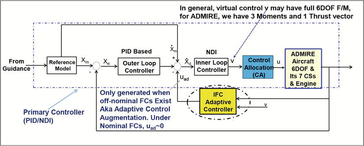
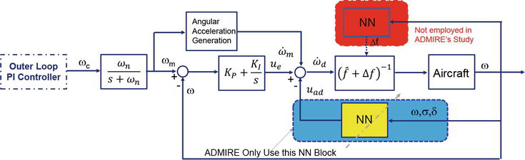
The ADMIRE fighter jet and its development of a generic flight controller are presented in detail in [6, 8]. However, for completeness, it is briefly described here so its baseline FCS interface with the IFC block added in an adaptive control configuration can be accurately described and presented. The ADMIRE’s generic dual loop design flight controller is employed in this study wherein the outer loop (i.e., slow dynamic loop) is designed to be command following. This amounts to achieving the angle of attack (AoA) command following for the longitudinal channel and for the angle of sideslip (AoS) and stability axis roll rate command following for the lateral and directional channels. The pitch/roll stick and rudder pedal commands are appropriately shaped and scaled to result in the AoA, stability axis roll rate, and AoS commands. A block schematic of the generic flight controller is shown in Figure 1. The inner loop (or fast dynamic loop) is designed using the Nonlinear Dynamic Inversion (NDI) adopted from [6] and detailed in the Appendix Section of the book for ADMIRE integration. The controller structure has the outer loop regulation of the slow dynamics consisting of the AoA, AoS, and flight path angle (FPA) by commanding the inner loop angular rates.
Figure 1.
ADMIRE dual loop autopilot with IFC implementation in an augmentation fashion – Baseline PID/NDI not using full state feedback.
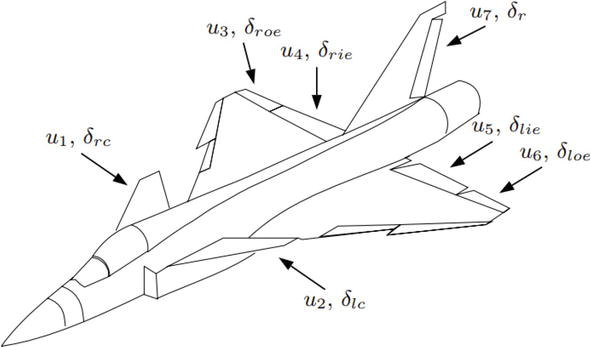
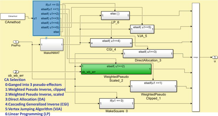
ADMIRE has seven aerodynamic control surfaces (CSs): left and right canards, left and right inboard elevons, left and right outboard elevons, and one rudder (see Figure 2). The canards and elevons can be operated together or in symmetric or differential deflections or individually. The roll, pitch, and yaw channels are controlled using these control surfaces. Hence, the transformation matrix has dimension seven by three (three desired control moments transformed to seven CS deflections). The dual loop PID/NDI autopilot is detailed in [7] for readers who are interested in seeing how the commanded state vectors of both the outer loop and inner loops are being formulated. This paper is intended to focus on the IFC algorithm description and how it differs from [4] in the implementation. Note that the current ADMIRE simulation has a single engine; however, the engine throttle controller has not been jointly integrated with the seven CSs main PID/NDI controller. Nonetheless, it is being accounted for in the existing seven CA algorithms block (see Figure 3 and [6] for algorithm details) to jointly map ‘virtual’ Force/Moment (F/M) command to ‘real’ effectors. For future UAV missions, especially for high-performance UAVs with flight speeds beyond Mach 5, a high-dimension effectors vector including advanced engine control effectors can be defined to address a more effective mixing scheme.
Figure 2.
ADMIRE’s seven aerodynamic control surfaces (ui, i = 1,2,…7).
Figure 3.
Current ADMIRE CA block with existing seven CA algorithms and IFC works quite well with any of those seven without imposing any restructuring CA action.
For the purposes of the roll axis control (the first column of Bv2r matrix, virtual to real (v2r)), the differential canards (KR2), and differential elevons (KR4) are used. For the pitch axis control (second column of Bv2r matrix, the symmetric canards (KP1) and symmetric elevons (KP3) are used (see [6, 8] for background). Finally, for the yaw axis control (third column of B matrix), the differential canards (KY2), differential elevons (KY4), and rudder (KY5) are used. The control allocation matrix is given by:
KR5 is the aileron to rudder interconnect gain. In case the optimizer finds a solution greater in magnitude than 1.2, it is reset to 1.2. The maximum differential deflection of the elevons is 25 degrees, whereas that of the rudders is 30 degrees. Therefore, limiting the KR5 gain to 1.2 prevents a control surface saturation of the rudder due to a roll command at the expense of some sideslip buildup during roll maneuver about the stability axis.
The maximum roll rate in the stability axis (velocity vector direction) is computed using the control allocation matrix determined above and used for the forward path (body x-axis direction) command scaling throughout the airspeed range.
3. Impact of two stuck inboard Elevons on the baseline NDI-FCS
In addition to the phase and gain margins, the following should be taken into consideration to ensure HQ criteria are met: (1) Effector performance degradation due to wear/tear or unexpected damage due to adversarial actions; (2) effector deflection and rate limits which could destabilize UAV FCS performance (see [10, 23]); (3) the AoA rate α̇ which should be safeguarded and not exceed an upper bound (e.g., <25 deg./s) throughout the flight envelope (with an AoA bound not to exceed 40 deg); (4) full stick maximum roll acceleration ‘Limit Bounds’ violation; (5) AoS limit during roll maneuvers; (6) model following errors bound violation (e.g., see [23]). One of the key concepts going forward to satisfy high-speed UAV mission requirements is to jointly optimize F/M at the full 6DOF CLAW level as full 6DOF (currently ADMIRE has not met this design goal) to compute the desired F/M demand (whether a completely healthy set of effectors or a reduced set of degraded capacity effectors exists) and to produce a realistic, attainable F/M response.
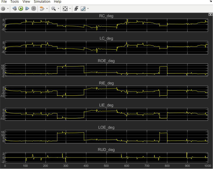
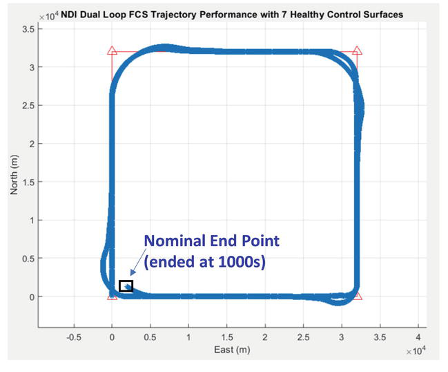
Figures 4 and 5 present the ADMIRE Baseline FCS CS and trajectory performance under nominal operating conditions with seven healthy CSs (RC: Right Canard, LC: Left Canard, ROE: Right Outboard Elevon, RIE: Right Inboard Elevon, LIE: Left Inboard Elevon, LOE: Left Outboard Elevon, and RUD: Rudder).
Figure 4.
7 CSs deflections under nominal FCs.
Figure 5.
ADMIRE nominal flight trajectory performance with seven healthy control surfaces.
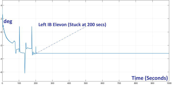
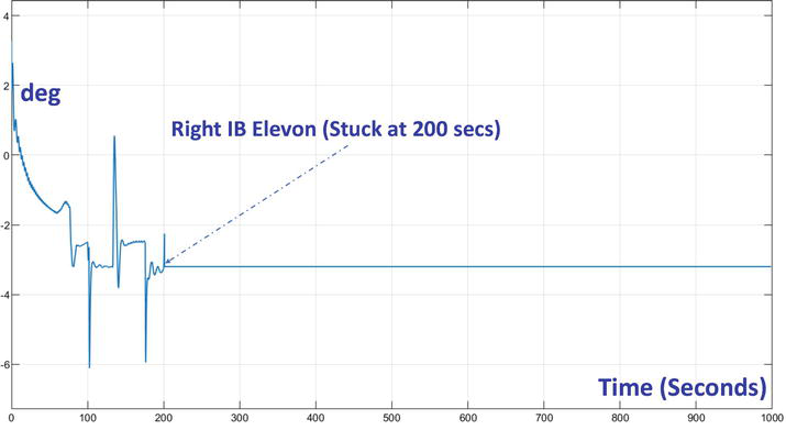
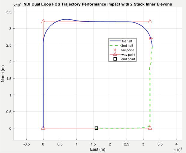
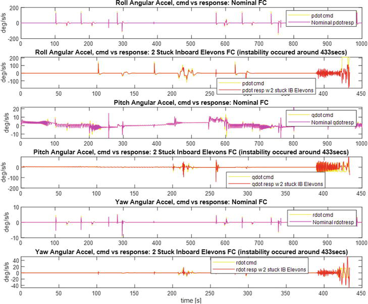
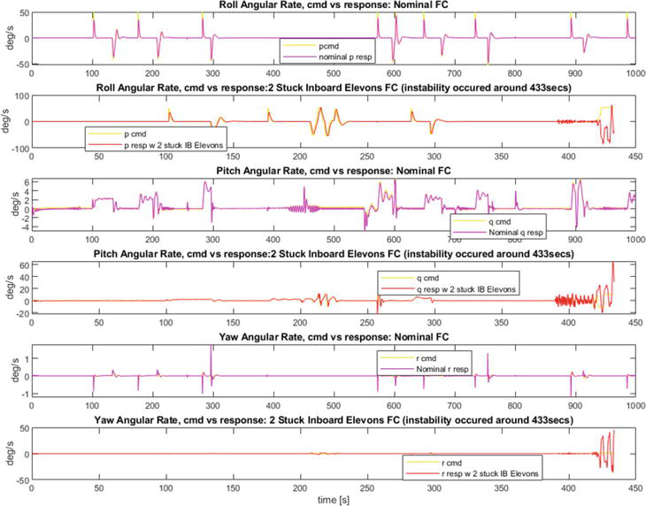
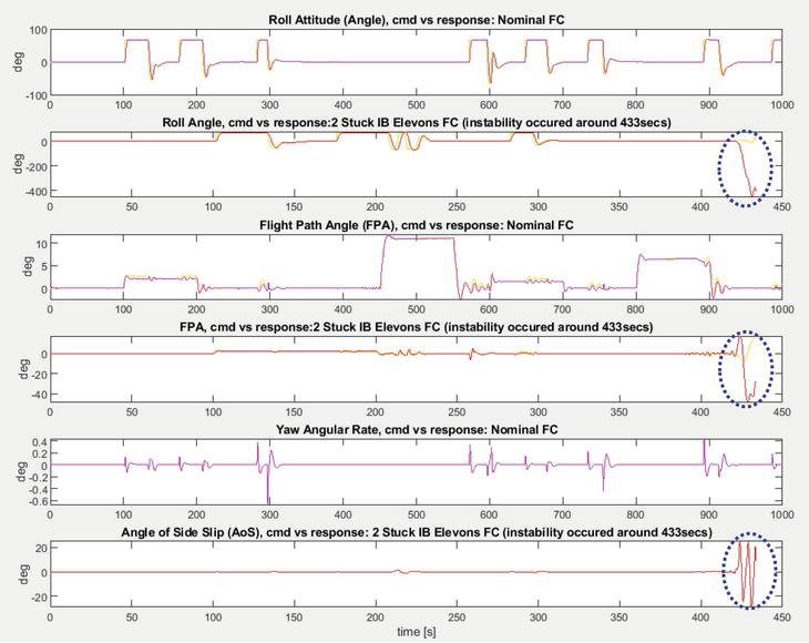
The ADMIRE FCS performance when two inner elevons are stuck at and beyond 200 seconds is shown in Figures 6 and 7. Under this failure, the ADMIRE flight trajectory is prematurely terminated at 433 seconds, as shown in Figure 8. The angular acceleration, angular rate, and attitude commands following comparisons are presented in Figures 9-11.
Figure 6.
Left inboard (IB) Elevon (stuck at 200 seconds).
Figure 7.
Right inboard (IB) Elevon (stuck at 200 seconds).
Figure 8.
ADMIRE flight trajectory performance degradation with two stuck IB Elevons (Mission ended prematurely with attitude pointing accuracy severely degraded).
Figure 9.
FCS angular acceleration command following via NDI – Nominal vs. 2 stuck IB Elevons.
Figure 10.
FCS angular rate command following via NDI – Nominal vs. 2 stuck IB Elevons.
Figure 11.
FCS Bank angle, flight path angle (FPA), and AoS command following via NDI – Nominal vs. 2 stuck IB Elevons (causing instability occurred at 433 secs).
These figures demonstrate that with two stuck IB elevons, the ADMIRE fighter aircraft FCS is not able to complete its mission. As a result, modern adaptive control augmentation of some fashion is needed to augment/assist the primary baseline FCS to cope with degraded flight conditions. In Section 4, we describe such an adaptive control augmentation concept using a hybrid adaptive control framework to best assist the primary FCS in completing its missions when subjected to unknown uncertainties and control effector failures.
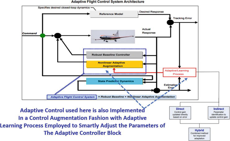
IFC algorithms have become popular in improving FCS performance, especially when employing the Optimal Control Modification (OCM) [30] as an adaptive law design modification, to further enhance the controller’s ability to cope with unknown uncertainties, aircraft damage, and disturbance attenuation since the early 2000s. We have teamed with NASA Ames Research Center to leverage their work on the IFC development for the NASA GTM piloted simulation [31], and the actual piloted F-15 and F-18 [32] flight tests of the OCM adaptive control law at NASA Armstrong Flight Research Center [4]. Toward this end, we have adopted their GTM-IFC design for robustness enhancement of the ADMIRE FCS when subjected to degraded control surfaces. The IFC block that we adopted from [4, 12] can be considered a hybrid design, as shown in Figure 12. The baseline adaptive control block (shown in yellow) is architected using the direct Model Reference Adaptive Control (MRAC), while the Neural Network Controller (NNC) block offers an adaptive learning process that allows the NNC-MRAC combination to achieve its adaptation in a more consistent and robust manner.
Figure 12.
Adaptive control motivation for why a hybrid design should be exploited to achieve verification and validation [12].
The IFC architecture developed for GTM [4] that is adopted here is shown in Figure 13. For the ADMIRE FCS performance enhancement subject to imperfect cancelation of the NDI CLAW due to off-nominal flight conditions (i.e., stuck control surfaces and/or complete loss of some control surfaces). For the sake of describing how the IFC design developed in [4] for aircraft flight control is applied to the ADMIRE’s robustness enhancement study, we re-use Section B of [4] (i.e., neural network (NN) direct adaptive control) and define its input/output (I/O) for the neural network adaptive control signal, uad, and how that signal is computed using the ADMIRE aircraft states vector.
Figure 13.
NNC architecture (yellow block) and their I/O Interface with ADMIRE Aircraft’s state vector.
4.1 NN-based adaptive control using conventional MRAC
The adaptive control augmentation vector uad is based on the adaptation law by Rysdyk and Calise [11] with a modification to include additional product terms that appear in the nonlinear plant dynamics described by Eqs. (31)–(33) of [4]:
uad=WTβnnC1C2C3C4C5C6E2
where βnn is a vector of basis functions computed using Kronecker products with Ci, i = 1;…; 6, as inputs into the neural network consisting of control commands, sensor feedback, and bias terms. More specifically, the product terms are
C1=V2ωTαωTβωTE3
C2=V21αβα2β2ααβ2E4
C4=pωTqωTrωTE5
C5=uωTvωTwωTE6
C6=1θϕCTE7
The NN basis function, βnn, then expressed as
βnn=C1C2C3C4C5C6TE8
The network weights W are computed by a direct adaptive law, which incorporates a learning rate G > 0 and an e-modification term [12] μ>0 according to the following weight update law
Ẇ=−ΓβnneTPB+μeTPBWE9
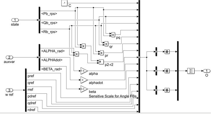
where Γ is an adaptation gain matrix, the matrix P solves the Lyapunov equation ATP+PTA=−Q for some positive-definite matrix Q, e is the model following error, and ||.|| is a Frobenius norm. Table 1 shows how P is computed for use in the ADMIRE IFC application. The βnnimplementation (of Eq. (8)) is shown in Figure 14.
%% See the IFC/NN Based Controller Block ifc.Kp_p = 3; ifc.Kp_q = 16; ifc.Kp_r = 5; Ap = −ifc.Kp_p; Bp = ifc.Kp_p; Cp = 1; Dp = 0; Aq = −ifc.Kp_q; Bq = ifc.Kp_q; Cq = 1; Dq = 0; Ar = −ifc.Kp_r; Br = ifc.Kp_r; Cr = 1; Dr. = 0; Kp = diag([ifc.Kp_p,ifc.Kp_q,ifc.Kp_r]); Pmat = lyap(-Kp’,eye(3)); Pmat = [0.1667 0 0 0 0.0312 0 0 0 0.1000]; Bmat = eye(3);
Table 1.
Lyapunov function block used in ADMIRE IFC block.
Figure 14.
βnn implementation in ADMIRE FCS IFC block (not full state FB).
The e-modification term in Eq. (9) provides robustness in the adaptive law [14]. The weight update law in Eq. (9) guarantees the stability of the neural network weights and the tracking error. The proof of this updated law using the Lyapunov method is provided by Rysdyk and Calise [13].
In the above expressions, [α, β, ϕ] are the AoA, AoS, and bank angle, [u v w] are the velocity vector components in the body frame, and ω is the vehicle body frame angular velocity vector.
5. Derivative-free model reference adaptive control (DF-MRAC)
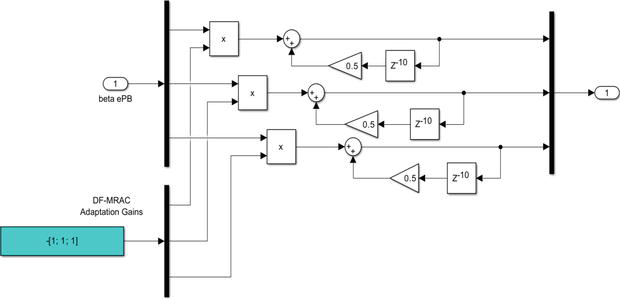
The DF-MRAC design framework is fully described in the recently published book written by Yucelen and Calise [9]. Here, we just want to describe how it is being used to solve the problem of two stuck inboard elevons by mixing its solution with the IFC architecture described in the previous section. The adaptive law in DF-MRAC has the form
Ŵt=Ω1Ŵt−τ+Ω̂2t,t>τE10
where τ>0, Ω1 and Ω̂2t satisfy:
0≤Ω1TΩ1<IsE11
Ω̂2t=κ2βxteTtPB,κ2>0E12
There is no need for e-modification as in (9) with this adaptive law, and the time delay τ can be freely chosen. DF-MRAC has many other advantages not present in MRAC that are illustrated in [9], including a natural robustness to unmodeled dynamics, greatly improved performance when augmenting a baseline controller that employs proportional + integral control, and the ability to treat uncertainties characterized by time-varying ideal weights. Conventional MRAC employs the assumption that the uncertainty must be characterized by a set of constant ideal weights, whereas with DF-MRAC, the ideal weights can be time-varying. This greatly reduces the burden on the designer to carefully select the correct set of basis functions in the design process. Another added advantage is that the time delay parameter employed in DF-MRAC adds an additional degree of freedom that has the added advantage of introducing greater memory into the learning process.
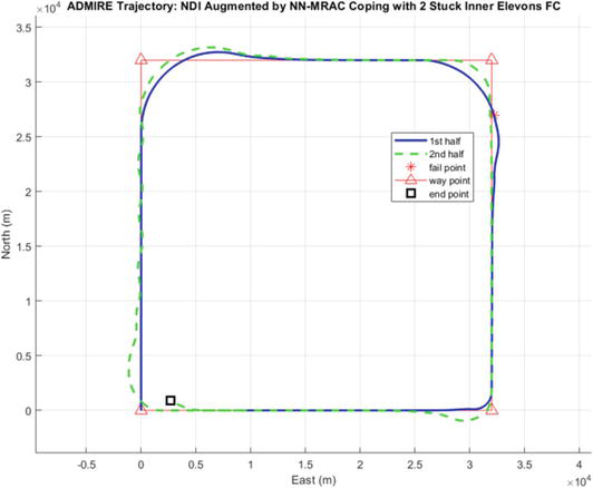
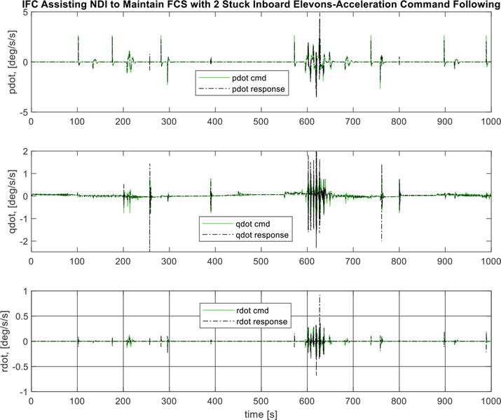
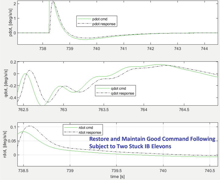
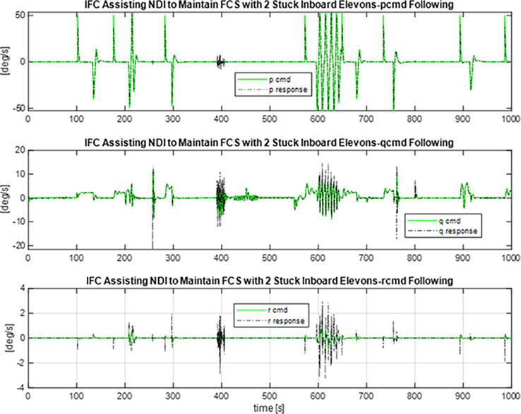
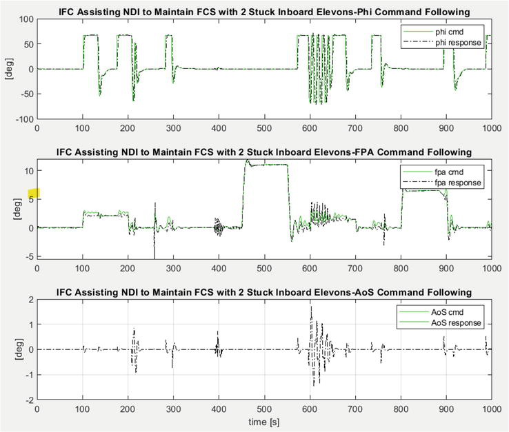
Figures 15 and 16 illustrate how DF-MRAC has added an option to the ADMIRE simulation. To date, it has been found that this option greatly improves the ability to handle failure in actuation (Figure 17). The ADMIRE aircraft is now able to restore its stabilization and maintain its desired mission performance for all the alternative CA methods that are currently implemented. This improved performance is illustrated in Figures 18, 19–22 for the same case of stuck inboard elevons, previously shown in Figures 6, 7, 8–11 without adaptation. Figures 18 and 19 present the IFC’s ability to maintain the aircraft controllability and restore stability when subjected to two stuck IB elevons and maintain a good command following this degraded flight condition (Figure 19).
Figure 15.
DF-MRAC implementation in parallel with derivative-based MRAC.
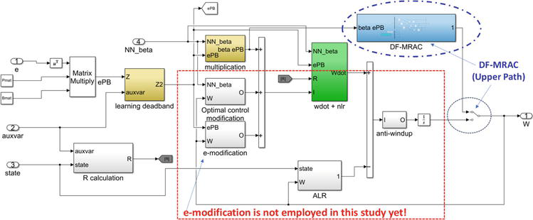
Figure 16.
DF-MRAC implementation within the IFC architecture.
Figure 17.
IFC/NDI restoring stabilization and control subject to stuck inboard Elevons sufficient to complete the Mission by employing DF-MRAC.
Figure 18.
Restored stabilization by IFC with improved angular acceleration command following subject to 2 stuck inboard Elevons (see zoom-in region in Figure 19 for command following accuracy).
Figure 19.
Restored stabilization by IFC with a zoom-in snapshot for command following restoration illustration (presented in Figure 18).
Figure 20.
Restored stabilization by IFC with improved angular rate command following subject to 2 stuck inboard Elevons.
Figure 21.
Restored stabilization by IFC with improved angle command following and tracking subject to 2 stuck inboard Elevons.
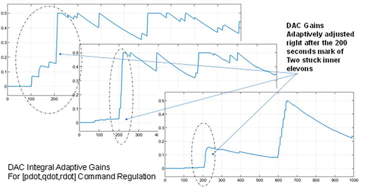
Figure 22.
DAC gain adaptation coping with two stuck IB Elevons.
6. IFC extension with direct adaptive control (DAC) algorithm to CA interaction
This section is a preliminary effort addressing F/M closed-loop regulation (i.e., enhancing F/M response to F/M commands generated by the inner loop NDI controller), which is the immediate layer tightly connected and interacting with the CA functional block presented in Figure 23. This is still being viewed as an adaptation protection layer which is implemented on the CLAW side (and not the CA side). This is a part of the hybrid direct and indirect adaptive control design framework presented earlier in Figure 12.
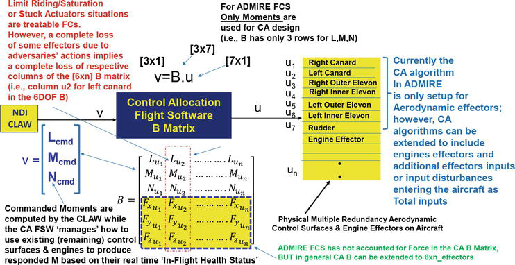
Figure 23.
Full F/M regulation with CA framework design coupled with CLAW where 3DOF force has been added to the baseline moments.
The closest connection to CA in an adaptive sense (without explicitly solving the dynamic CA problem as described in [20, 21, 22]) is to actively regulate the angular acceleration error with some quadratic minimization adaptive regulator. We chose the direct adaptive control algorithm presented in [23] (and recently demonstrated in [10]) to actively enforce angular acceleration commands in the presence of degraded effectors. Surprisingly, the use of such a direct adaptive control scheme as an adaptive acceleration error regulator works quite well for both stuck control surfaces and degraded effector’s deflection angle and deflection rate limits (see Figure 22 for its adaptive gain real-time adjusting as a function of model following errors of angular acceleration vector).
The CA design framework has been employed by the aircraft, UAVs, and spacecraft industries for more than five decades. However, various design algorithms and their design evolution are only captured by technical publications and internal technical memorandum until 2017 with a formal textbook by Durham et al. [6]. This textbook is viewed as a compilation of multi-decade research and development (R&D) in CA algorithms for aircraft FCS, especially with the mixing of NDI-based design and the Cascaded Generalized Inverse (CGI) for X-35 and F-35 applications [7]. Readers are referred to Chapters 7 and 8 of the textbook [6] for the formal CA design framework captured therein and CA applications to the X-35 in Chapter 9. The concepts of Desired Commands (for Commanded Moments Generation by the inner loop NDI CLAW) vs. Attenable Moments Set (AMS) via Admissible Control Effectors captured in Appendix A of [6] and how they are being connected to the aircraft FCS design is captured in Appendix B. Note that the CA framework should be generalized for 6DOF control with full 6DOF F/M command following as described in Figure 22 rather than solely moment or torque regulation.
The CA design framework interconnected to the CLAW side has been an active research topic during the last 10 years (e.g., innovative control effectors (ICE) [16] and balancing/resolving actuators redundancy via control vs. control allocation [17]). It has become an important topic for maintaining high-speed UAV missions, especially under stressful operating conditions that include degraded effectors due to thermal impact or damages resulting from adversarial actions (see [18, 19]).
The primary goal of adaptive CA dealing with control effector failures is to dynamically reshape the CA multiple effectors blending matrix B (in Figure 22) to explicitly zero out the corresponding column of such a failed effector so that the inner loop NDI CLAW does not rely on the same original number of healthy effectors for F/M contribution. In this example case, the control effector will be the second column, as illustrated in Figure 23. Therefore, the new B matrix used by the CLAW will now have a new dimension of [3x6] matrix (restructuring the B matrix by removing the second column of its original [3x7] matrix) if the second effector has been detected and declared as a complete loss of its operational capacity. Of course, other CA algorithms could offer effectors fault tolerant CA capabilities without explicitly restructuring the mixing matrix B such as in [24].
The study presented herein, adaptive control augmentation via IFC to assist the primary baseline FCS subject to off-nominal FCs, is not new (e.g., see [4] and its cited references therein or [12] for a formality of adaptive control verification and validation). We re-use such an attractive IFC solution for high-speed UAV applications as an added extra layer of flight control protection, exploiting its self-learning and adaptation consistency. One important finding is that the IFC DF-MRAC works very well with all existing seven CA algorithms to maintain FCS performance, while the DAC algorithms are only operational to three of them using the same set of adaptation parameters selection. This means the DAC algorithm requires retuning of its adaptation parameters ([ΓI, Γp, σ], see [23]) for different CA algorithms, while the IFC algorithms do not require retuning. The current IFC design will be continuously evaluated, revised, and upgraded to address more formal failure cases and to mature its design to serve more realistic high-speed UAV missions.
Future directions will extend the IFC design to address the functional CA performance aspects (augmentation of the CA functional blocks subject to effectors performance degradation, e.g., see [18, 19, 20, 21, 22] or [24]) rather than just adaptation augmentation added on in the control law side of the FCS. As mentioned earlier in Section 5, there are two main paths (e.g., see [17]) to dynamically size/shape and determine the commanded effectors: (1) directly determine the real deflection of effectors from the applied optimal control and (2) use optimal control or NDI to compute the total F/M, and then use the actual CA function (via the multiple effectors mixing matrix B in Figure 23) to compute individual effectors’ deflection in real-time. Aircraft CA algorithms have been extensively studied during the past two decades (e.g., see [6] and references cited therein) and are still considered an active research area in addressing CA mixing to achieve (i) optimal performance when all effectors are healthy and (ii) suboptimal performance when effectors are in degraded operating conditions (e.g., see [33] for actively reshaping the effector’s blender solution B matrix in real-time (see Figures 4 and 5 of [33])) while still able to maintain the designated mission.
Future improvements are contemplated for IFC in general and DF-MRAC in particular. These include:
Adaptive hedging to improve response when actuator position and rate limits are active and to account for the fact that actuators are bandwidth limited (see [25]).
Adaptive loop transfer recovery to guarantee the gain, phase, and time delay margins of the baseline design are preserved under IFC (see [26]).
A direct method for adaptation to actuator failures that do not require augmentation of the CA function blocs. This involves a modification to Eq. (11) as described in Section 3.4 of [9].
Application of a neural network-based control to attenuate external disturbances developed by Levin and Ioannu in [27].
Possibility of employing the multiple model adaptive mixing schemes developed in [28, 29] to ensure a wider region of adaptation without model switching.
This study is part of a bigger campaign in preparation for future high-speed UAV business pursuit and was partially funded by the Jesplsoft IRAD Program. The NASA partnership forming and support are greatly appreciated.
1.Eva Wu N. Reliability analysis for AFTI-F16 SRFCS using ASSIST and SURE. In: Proceedings of the American Control Conference Anchorage, AK May 8-10, 2002
2.Khan R, Williams P, Riseborough P, Rao A, Hill R. Active fault tolerant flight control system design - A UAV case study. arXiv:1610.03162v1. 2016
3.Hu B, Seiler P. A probabilistic method for certification of analytically redundant systems. IEEE. 2013
4.Nguyen N, Krishnakumar K, Kaneshige J, Nespeca P. Flight dynamics and hybrid adaptive control of damaged aircraft. Journal of Guidance, Control, and Dynamics. 2008
5.Forssell L, Nilsson U. ADMIRE The Aero Data Model in Research Environment Version 4, Model Description, Report No. FOI-R–1624–SE, FOI Swedish Defense Research Agency, Systems Technology, SE −164 90, Stockholm. 2005
6.Durham W, Bordignon K, Beck R. Aircraft Control Allocation. Wiley Aerospace Series; 2017
7.Bordignon K, Bessolo J. ‘Control allocation for the X-35B,’ AIAA 2002-6020. In: 2002 Biennial International Powered Lift Conference and Exhibit, 5–7 November 2002. Virginia: Williamsburg
8.Lathasree P, Pashilkar AA, Sundararajan N. Application of generic flight controller design approach for a Delta canard fighter aircraft-ADMIRE. In: Sixth Indian Control Conference (ICC) December 18–20, 2019. India: IIT Hyderabad; 2019
9.Yucelen T, Calise AJ. Derivative-free adaptive control. AIAA. 2023;267
10.Lam Q. Direct adaptive control augmentation and dynamic control allocation algorithms subject to stuck control elevons for aircraft flight control robustness and performance enhancement, Jesplsoft IRAD Report. 2023. Available from: https://Jesplsoft.com
11.Li X, Liu S, Guo F, Zhang S. Fault-tolerant control based on control allocation for hypersonic vehicle with actuator stuck fault. IEEE. 2019
12.Nguyen N. Verification and Validation Challenges for Adaptive Flight Control of Complex Autonomous Systems. AIAA; 2018
13.Rysdyk RT, Calise AJ. Fault tolerant flight control via adaptive neural network augmentation. In: AIAA Guidance, Navigation, and Control Conference, AIAA 1998–4483. 1998
14.Narendra KS, Annaswamy AM. New adaptive law for robust adaptation without persistent excitation. IEEE Transactions on Automatic Control. 1987;32(2):134-145
15.Calise AJ, Sharma M, Corban JE. Adaptive autopilot Design for Guided Munitions. Journal of G&C Dynamics. 2000
16.Niestroy MA, Dorsett KM, Markstein K. A Tailless Fighter Aircraft Model for Control-Related Research and Development. AIAA; 2016
17.Häarkegård O, Glad T. Resolving actuator redundancy: Optimal control vs. control allocation. 2004. Available from: http://www.control.isy.liu.se
18.Yong F, Ji-Hong Z, Jia-Qiang Z, Zeng-Qi S. “Genetic Algorithm Based Constrained Control Allocation for Tailless Fighter,” the National High Technology Research and Development Program of China Grant #2005AA751010
19.Yang L-Y, Zhong Y-W, Shen G-Z. Control allocation and Management for Aircraft with multiple effectors. IEEE. 2009
20.Lu B, Ma J, Zheng Z. Adaptive closed-loop control allocation based fault tolerant flight control for an over-actuated aircraft. IEEE. 2019
21.Jingping S, Xi LVY, Xiaobo Q, Jing S. A coordinated control method of thrust vector and aerodynamic surfaces based on control allocation technology. IEEE. 2018
22.Cui L, Zuo Z, Yang Y. A control-theoretic study on iterative solution to control allocation for over-actuated aircraft. IEEE. 2018
23.Lam Q, Barkana I. Direct Adaptive Control Treatment to Flight Control Input Saturation. AIAA; 2005
24.Hamayun MT, Edwards C, Alwi H, Bajodah A. A fault tolerant direct control allocation scheme with integral sliding modes. International Journal of Applied Mathematics and Computer Science. 2015;25(1):93-10
25.Johnson EN, Calise A. Limited authority adaptive flight control for reusable launch vehicles. Journal of Guidance, Control and Dynamics. 2003;26(6):926-913
26.Calise AJ, Yucelen T. Adaptive loop transfer recovery. AIAA Journal of Guidance, Control, and Dynamics. 2012;35(3):807-815
27.Levin J, Ioannu PA. Adaptive control with neuro-adaptive disturbance rejection. In: 17th Mediterranean Conference on Control & Automation Makedonia Palace. Thessaloniki, Greece; 2009
28.Kuipers M, Ioannou P, Fidan B, Mirmirani M. Analysis of an adaptive mixing control scheme for an Airbreathing hypersonic vehicle model. In: American Control Conference Hyatt Regency Riverfront, St. Louis, MO, USA June 10–12, 2009. 2009
29.Lam Q, Cloutier J, Hart A, Stockbridge S. Exploring multiple model control mixing for robustness and performance enhancement of hypersonic vehicles. In: Proceedings of the Joint Army Navy-NASA-Air Force Conference, December 2014
30.Nguyen N. Model-Reference Adaptive Control - A Primer. Springer-Verlag; 2018. ISBN: 3319563920
31.Campbell S, Kaneshige J, Nguyen N, Krishnakumar K. An adaptive control simulation study using pilot handling qualities evaluations. In: AIAA Guidance, Navigation, and Control Conference, AIAA-2010-8013, August 2010
32.Nguyen N, Hanson C, Burken J, Schaefer J. Normalized optimal control modification and flight experiments on NASA F/A-18 aircraft. AIAA Journal of Guidance, Control, and Dynamics. 2017;40:1061-1075
33.Harris JJ, Stanford JR. F-35 Flight Control Law Design, Development, and Verification. AIAA Aviation Forum; 2018
Written By
Quang M. Lam, Anthony J. Calise and Nhan T. Nguyen
Submitted: 18 December 2023Reviewed: 19 December 2023Published: 13 March 2024