
Abstract
In this chapter, after describing how the microbial fuel cell operates and how the chemical energy resulting from the oxidation of a substrate through oxidation/reduction reactions is converted into electricity with chemical reactions, the factors affecting the performance of the fuel cell including the effect of temperature, the effect pH, external resistance, type of electrode, size, and distance of electrodes, type, and composition of microorganisms, as well as the shape, structure, and size of the chamber have been investigated. Since the purpose of fuel cell design is to produce electric current from microorganisms, therefore, the current density criterion and how to calculate it are briefly explained.
Keywords
- microbial fuel cell
- various fuel cell structures
- size and distance of electrodes
- microorganism
- power density
1. Introduction
The microbial fuel cell is an electrochemical device that converts the chemical energy contained in organic and inorganic materials in the environment or waste into electrical energy by using microorganisms as a biocatalyst. The driving force in these cells is the oxidation-reduction reactions of a raw material in which a microorganism is used as a catalyst [1].
The microbial fuel cell has a structure more or less similar to polymer fuel cell and includes an anode and anode chamber, cathode and cathode chamber, proton transfer membrane, precursor, and microorganism. In microbial fuel cells, a microorganism is used as a biocatalyst, which produces electrons and protons by decomposing and oxidizing organic materials. Only in its anode, the chemical transformations are done in a different way, as a result, its anode structure is different from the polymer cell anode structure. The working principles of these cells are the same as those governing other fuel cells. The main difference is that the catalysts in these cells are microorganisms or enzymes, and as a result, there is no need for precious metals. The reaction conditions are very simple and to carry out the reaction, ambient temperature, air pressure, and neutral pH are needed. The fuel cell system can be operated for a long time [2]. The advantages of this type of cell are:
Does not need a catalyst.
It has good stability during long working time.
Reactions are automatically adjusted and do not require recharging.
There is no need for a heat exchanger or a cooler to carry out the reaction.
Biocatalysts are used in microbial fuel cells and these biocatalysts have the following prominent features:
Can be used in moderate and low temperatures.
Biocatalysts are cheaper than metal catalysts.
They are renewable and can be used for different types of cells with different substrates [3].
Microorganisms have the ability to produce active substances that can be produced in a specific environment, then transferred to the cell as fuel; the microbial fermentation process can take place directly in the anode part and the same chamber [4].
The microbial fuel cell must be designed to provide anaerobic conditions in the anode chamber because the presence of oxygen in the anode chamber prevents the production of electrons or by absorbing electrons and protons, prevents the formation of electricity in the external circuit. Also, the air injected in the cathode should provide dissolved oxygen for the reaction [5]. Based on their performance, microbial fuel cells are designed as single-chamber and double-chamber. Designing two-chamber systems that can operate in two continuous and discontinuous modes is difficult due to its complex design. Designing single chamber systems is easier and cost-saving. Usually, these types of systems only include an anode chamber, and the cathode electrode is directly exposed to air. The outline of a microbial fuel cell device for both cases is shown in Figure 1.
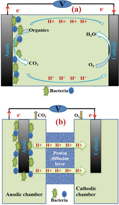
Figure 1.
A view of the performance of the microbial fuel cell (a) single chamber and (b) double chamber.
The substrate is oxidized as fuel by microorganisms in the anaerobic chamber where the anode electrode is located and releases electrons and protons. Protons are transferred to the cathode compartment through the proton exchange membrane and are converted into water vapor in the reaction with oxygen. The presence of oxygen in the anodic chamber prevents the production of electrons or cuts off the flow of electricity by consuming electrons and protons. Therefore, the device must be designed in such a way as to provide anaerobic conditions in the anodic chamber. Two electrodes are connected by a wire that contains a load (a device that consumes energy), but in the laboratory, they use a resistor as a load. Basically, the membrane is permeable for the protons produced in the anode, and they can move to the cathode, where they combine with oxygen and electrons transferred through the wire to form water. The electric current produced by a microbial fuel cell can be measured in the laboratory by observing the voltage drop across a resistor using a voltmeter connected to a computer [6].
A wide range of organic substances from simple molecules such as carbohydrates and proteins to complex mixtures of organic substances found in food, human and animal wastes, chocolate and beer wastes as precursors as materials available to different microorganisms for use in the system Microbial fuel cells are used [7]. Microbial fuel cells are divided into two groups based on the mechanism of electron transfer, with and without a mediator. Mediated microbial fuel cells are electrochemically inactive and electron transfer is carried out by mediators such as
Some microalgae, yeasts, and fungi have also been reported to produce electric current in MFCs, which are used as a substrate or as an aid to the anode or cathode. The nomenclature of the microorganisms used has not yet been standardized. However, some terms have been proposed for microorganisms that can exogenously transfer electrons to the anode without using any artificial mediators. Some of these terms include exoelectrogens, electrogenic microorganisms, electrochemically active bacteria, anodeophiles, anode-respiring bacteria, and electrophiles. In addition, microorganisms can be named according to their performance in MFC. Microorganisms that donate electrons to the electrode (anode) in MFCs are called electrode reducers, while microorganisms that accept electrons from the electrodes are called electrode oxidizers. Common bacterial species for electricity generation in MFCs are
2. Factors affecting the performance of microbial fuel cells
To design a fuel cell with industrial applications, in order to produce electricity from municipal waste water and simultaneous purification, various factors are involved. Fuel cells with a catalytic reaction, with the help of microorganisms, oxidize organic matter or biomass in the anode section and produce carbon dioxide, protons, and electrons. Microorganisms formed in the anode part play the role of catalyst in analogy with chemical fuel cells. Depending on the different feeds in the fuel cell electrolyte, various reactions can occur in the fuel cell components. For example, if the feed in the anode is an affluent and oxygen acts as an electron acceptor in the cathode, then the reactions in the cathode and anode will be as follows [10]:
In the anode:
In the cathode:
General reaction:
Electrons reach the cathode through an external circuit and in the presence of proton (H+) which comes to this part through the membrane, they combine with the oxygen blown in the cathode and produce water; In this way, this process continues many times with the completion of the circuit. Much researches has been done to optimize the parameters and increase the efficiency of microbial fuel cells in order to overcome the limitations of proton and electron transfer, increasing the surface area and reactivity of the electrodes. Several factors including the effect of temperature, effect of pH, external resistance, type of electrode, size and distance of electrodes, type and composition of microorganisms, shape, structure, and size of the chamber as well as the effect of various chemical additives have been investigated. In this study, we discuss some effective factors as follows:
2.1 Effect of temperature
Temperature is an important parameter in the decomposition process and has a major effect on the initial biolayer formation process and on its bioelectrocatalytic performance. Also, biofilms grown at higher temperatures tend to have higher electrochemical activity than those grown at lower temperatures [11]. Therefore, operating temperature provides an effective strategy to reduce MFC start-up time and improve energy efficiency. The optimal temperature of microorganisms is known to be in the range of 35 to 40 °C. When the temperature drops below this value, the activity of microorganisms gradually decreases. The performance of microbial fuel cells based on the production of electricity from wastewater treatment is generally improved in a higher temperature range, although it has been proven that microbial fuel cells are not as sensitive as conventional anaerobic analyzers in a relatively low-temperature range (i.e. between 4 and 15 °C). The advantage that microbial fuel cells have compared to other conventional decomposers is the ability to decompose at low flow rates and low temperatures, to the extent that this characteristic causes that in cold regions where the rate of urban sewage is relatively low, it can be Microbial fuel cell was used as a suitable device for wastewater treatment.
In biochemistry, a measure in the form of Q10 is expressed as the rate of change of a biological system as a result of an increase in temperature by 10 °C in the temperature coefficient or Eq. (1):
where R is the rate and T is the temperature in degrees Celsius or Kelvin. Generally, the Q10 value is between 1 and 3.
Focusing on MFCs, temperature changes in the system in terms of kinetics (activation energy, mass transfer coefficients, solution conductivity…), thermodynamics (Gibbs free energy, electrode potentials…), system outputs (i.e. output power and amount removal of COD) and affects the nature and type of microbes. These changes are given in Eqs. (2)–(4):
Which is the relationship Eq. (2) energy potentially available, relationship Eq. (3) Electromotive force, and relationship Eq. (4) Organic matter oxidation. Although the research on MFC has increased greatly in recent years, systematic information on the effect of temperature on microbial fuel cells is very scarce and has only been conducted in a range of different temperatures from 4 to 35°C. In addition, different conditions and systems have been used in different studies, leading to large variations in the reported parameters for the target temperature. This feature makes it difficult to determine the effect of temperature on performance from the various available data. When the temperature in an MFC system changes, the composition of the anodic microbial consortium changes correspondingly. This change along with the modification of other parameters such as diffusion coefficients, activation energies, etc. will affect the system outputs including I, P, and CODrem rate [12].
2.2 Effect of pH
The pH value in the anode chamber can affect the metabolic activity of microorganisms and also the electron and proton (H+) production mechanism and thus the efficiency of microbial fuel cells. In general, microorganisms respond to environmental pH changes by carrying out processes such as proton exchange and amino acid decomposition. Changes in pH lead to changes in parameters such as ion concentration and membrane capacity. For example, in a tested microbial fuel cell, the pH of the anodic solution reached its minimum value after 30 to 40 hours and after feeding. During this experiment, under two temperature ranges, i.e. (8 to 22 °C) and (20 to 35 °C), when the pH of the input feed was 7.4, the pH of the anodic solution reached its lowest value, i.e. 6.2, after the mentioned time. This expression shows that the proton exchange through the membrane was slower than the production rate in the anodic chamber. Therefore, protons are only limited to the reaction in the cathode chamber where oxygen is present as an oxidant, and as a result, there is an accumulation of protons in the anode chamber, which leads to a drop in pH. Therefore, the performance of a fuel cell is at its best when the pH of the anode chamber is kept constant using a buffer solution, and it causes the same amount of proton produced in the anode to actually pass through the membrane and reach the cathode [13].
2.3 External resistance
External resistance can affect the power performance of the MFC by regulating the electron flow from the anode to the cathode. According to Jacobi’s law, the optimal external resistance to produce maximum energy in MFC should be close to its internal resistance. External resistance can also affect the structure of the anode biofilm. The external resistance controls the flow of electrons from the anode to the cathode and affects the output potential and current of MFCs according to Ohm’s law. As a result, the output power is affected by the external resistance. Changes in external resistance in addition to electricity production also affect the relative diversity of the microbial community [14]. One study showed that anodic biofilms developed under 100 Ω external resistive pressure showed better biofilms compared to samples subjected to controlled pressure of 1 MΩ [15]. This is not surprising, since an external charge changes the rate and speed of electrons exiting the anode. This change in bacterial metabolism always has an effect and as a result, causes a change in the microbes present in the anode biolayer.
2.4 Electrode type
The anode material is very important in the overall performance of MFC. Anode characteristics affect biofilm formation, electron transfer, and substrate oxidation. To achieve higher performance of MFCs, the selected electrode materials should have good biocompatibility, large surface area, low electrical resistance, good corrosion resistance, and chemical stability [16]. Among the properties of anodic materials, cross-sectional area, pore structure, and surface hydrophobicity have a significant effect on the formation of anodic biofilm. Du et al. [17] reported that polydopamine (superhydrophobic semiconductor) accelerated the formation of anodic biofilm and improved the performance of MFCs. This is in agreement with a previous report showing that anode hydrophobicity can facilitate the attachment of microbes, which in turn increases biofilm formation and power generation [18]. In this study, it has also been shown that such properties increase the proportion of electron-generating elements (eg, bacterial protein) in the biofilm. The most important features to improve the surface interaction of materials used in the anode electrode are: i) Electrical conductivity ii) Corrosion resistance iii) High mechanical strength iv) Developed surface v) Environmentally friendly and vi) Low cost. Metal materials and all kinds of carbon materials, including carbon cloth, carbon brush, carbon rod, carbon mesh, carbon veil, carbon paper, carbon felt, granular activated carbon, granular graphite, carbonized cardboard, graphite plate, and reticulated vitreous carbon, all of these have the characteristics. Among the metal materials, stainless steel plate, stainless steel mesh, stainless steel scrubber, silver plate, nickel plate, copper plate, gold plate, and titanium plate were used as anode electrode materials. Carbon cloth is a carbon material that is mostly used as an anode material due to its high surface area and relatively high porosity. Also, carbon fabric shows high electrical conductivity, flexibility, and mechanical strength in forming more complex three-dimensional structures. The negative aspect is the cost, which is generally very high. Carbon brush is a very interesting material in which carbon fibers are twisted together with a very high surface area and an optimal area-to-volume ratio. Carbon mesh is also commercially available at a relatively low cost and relatively low electrical conductivity. The main problem of carbon mesh is low mechanical strength, which can lead to low durability in high flow conditions. It can also be folded to make a 3D electrode, but the porosity is low. Carbon veil is a very cheap carbon material with relatively high electrical conductivity and high porosity, but its single layer is quite fragile. Because this material is versatile, it can be folded to form a solid, porous three-dimensional electrode. Carbon paper is a flat, relatively porous but expensive, and fragile carbonaceous material that is mainly used on a laboratory scale. Carbon felt performance is usually due to its high porosity and high electrical conductivity characteristics, similar to a carbon veil, large pores allow bacteria to penetrate through the structure. The cost is relatively low and the mechanical strength is high depending on the thickness of the material. Granular activated carbon is also biocompatible, low cost, and very porous but has very low electrical conductivity. In this case, the surface area is very large, but the surface area available for the interaction of bacteria is small because most of the available surface area is on the nanometer scale. The properties of granular graphite are similar to Granular activated carbon, except for a much lower level due to lack of activation. As a result, its electrical conductivity is much higher like Granular activated carbon. Therefore, it is used as a packing material instead of an independent anode. Carbonized cardboard is also a three-dimensional material that is made by single-walled corrugated cardboard from recycled paper subjected to heat treatment (1000 °C) for 1 hour in an inert atmosphere, which has very low cost, high electrical conductivity, and high porosity. A graphite sheet or sheet is a very simple electrode that ensures high electrical conductivity and has a low surface area and surface-to-volume ratio, resulting in lower output levels than porous materials. Reticulated glassy carbon is highly conductive and has high porosity, which allows the biofilm to penetrate the entire structure and colonize the entire electrode. But it is too fragile and too expensive to use in MFCs. Other carbon materials, such as carbonized plant stems, activated carbon nanofibers, and electrospun carbon fibers, have also been used as carbon-based anode electrodes.
Several metallic materials have been used as anode electrodes in MFCs. The most important of which is stainless steel with the main feature of being highly conductive, resistant, and cheap. Other metals such as copper, nickel, silver, gold, and titanium were also investigated as anode electrode materials. Surface chemistry and surface morphology play a key role in the interaction between the biofilm and the anode electrode. Three factors can affect the interaction between the single-cell surface, at the biofilm level and, the integrated system level: 1) Bacterial surface adhesion can be improved by changing the surface chemistry. 2) Surface hydrophilicity/hydrophobicity during bacterial attachment, 3) Oxygen or nitrogen functional groups that facilitate bacteria/surface interactions, and 4) Immobilized mediators. Theoretically, an increase in level should lead to an increase in flow. It was shown that the current produced by the carbon-felt anode was higher than that produced by the flat carbon graphite anode, but there was no correlation between the actual surface and the current. This indicates that, among other reasons, not all the available area has been successfully colonized by the biofilm. The transition from a smooth surface to a more complex three-dimensional surface requires the possibility of encountering the limitations caused by the phenomena of diffusion transfer of products and reactants, as well as the relative pH gradient. These parameters seem to be of great importance for long-term operation. Finally, at the system level, the anode electrodes must be designed to avoid clogging or “dead zones” [19].
2.5 Size and distance of electrodes
In order to achieve better performance in microbial fuel cells, the materials used in the electrode should be more active surfaces with relatively lower activation losses.
The amount of produced current is proportional to the active surface of the electrode. It has been shown in a study that graphite felt with an area of 200 cm2 produces three times more current than graphite rods with an area of 65 cm2 [20]. Due to these characteristics, Granular activated carbon is mainly used as a packing material instead of an independent anode. Granular activated carbon must be packed to increase the conductivity, and this may lead to possible blockages in the flow-through configuration of the MFC.
Reducing the distance between the anode and cathode electrodes, by reducing the internal resistance, facilitates the transfer of protons from the cation exchange membrane. In such a situation, microbial fuel cells have shown good performance when the two electrodes are as close as possible so that short circuit does not occur. For example, if the distance between the electrodes is reduced from 4 to 2 cm, the production power increases by 168%, and if this distance is reduced from 2 to 1 cm, the production power in the fuel cell decreases from 811 mW/m2 to 423 mW/m2. This paradoxical behavior is probably due to the damage caused by oxygen penetration from the cathode to the microorganism in the anode. It is reminded that if the high internal resistance limits the production power, increasing the anode level does not have a noticeable effect on the output power [21].
Different studies of electrode size in different designs of microbial fuel cells (different scales of electrodes with different volumes) have shown that the size of the electrode has a direct effect on the power density and electric current produced by the fuel cell. By making the electrode and examining the size of the electrode on both small and large scales, the ability to produce electricity has been studied. The results have shown that by changing the size of the electrode in the microbial fuel cell and increasing its cross-section, the intensity of the electric current changes. Also, by reducing the size of the electrode in the small-scale microbial fuel cell, the losses in the activation area are reduced [22]. Therefore, by reducing the size of the electrode in a small-scale microbial fuel cell, the intensity of the electric current and the power density is increased, and the losses in the activation area of the polarization diagram are also reduced to a large-scale. Also, the effect of electrode size by considering two different scales in electricity generation has been studied by Yan et al. [23]. They showed that the power density of the larger anode is higher than that of the smaller one. In a similar study, Seong-Won Im et al. [24] showed the effect of electrode size on the maximum voltage and power density generated, indicating a decrease in these quantities by reducing the scale of the electrode. In another study by Zuraidah Rasep et al. [25] with three electrodes with sizes of 6 × 6, 7 × 7, and 8 × 8 cm, the maximum current produced was 0.72 mA for the 8x8cm electrode and 0.56 mA for 6× 6 cm, but in a study, Eduardo et al. [26] examined the electrode-surface area/anode-compartment volume ratio instead of the electrode size and showed that by decreasing the anode-compartment volume, the amount of the electricity generation increases and Also, with the increase of ESAVR from 0.15 to 0.75 cm2 cm−3, the intensity of currents increases from 583 to 2416 mA m−2. These studies show that the size of electrodes in MFCs plays an important role in electricity generation.
2.6 Microorganisms in the microbial fuel cell
As mentioned, the microbial fuel cell is a device that uses microorganisms to produce electric current through the oxidation of organic materials. According to Figure 1, microorganisms play a role by taking electrons from reactants and delivering these electrons from the biofilm to the surface of the anode electrode. It is true to say that microorganisms act as catalysts because they mediate the transfer of electrons from the reactant to the system. However since they absorb energy from the surrounding environment and reactants for their growth and survival, it is not similar to chemical catalysts [27]. The biofilm that includes microorganisms can be in contact with the electrode in two ways, mediated and unmediated. In the intermediate state, substances such as
Few articles described the cases of gram-positive bacteria (MFC -
Microorganisms-electrogens have the ability to use a wide range of substrates depending on the species. Therefore, the production of electric current by bacteria
Many species
Not all bacteria in the population participate in the transfer of electrons to the electrode, because the composition of bacteria in the anode compartment depends on the type of substrate used. Microorganisms used in MFC as biocatalysts are not only species such
Microorganisms carry out electron transfer in MFCs in two ways, direct and mediated. Certain types of bacteria, metal reducers being the most important, can directly transfer electrons to the anode. Electron transfer mediators are mostly electrochemically inactive and cannot directly transfer electrons to the electrode. In this case, it is possible to use soluble substances known as redox mediators that facilitate electronic transfer. Electrochemically active microorganisms can create intermediate junctions under certain conditions that can play a role in extracellular electron transfer processes. This can happen in two ways by producing secondary and primary metabolites. Secondary metabolites (endogenous intermediates) are redox-active substances and act as reversible terminal electron acceptors that transfer electrons from a bacterial cell to a solid oxidant (MFC anode) or transferred to the aerobic layers of the biofilm, where they are oxidized and can participate again in redox processes. Primary metabolites, for example, sulfide or hydrogen, also act as redox mediators [28].
2.7 Microbial fuel cell structure
One of the most important parameters in the design of microbial fuel cells is the design of the cell chamber structure. Types of microbial fuel cells based on the structure of the cell compartment, we can mention things like H-shaped microbial fuel cells, double-reservoir microbial fuel cells, single-compartment microbial fuel cells, tubular microbial fuel cells, and microbial fuel cells with upward flow [29]. Single-chamber microbial fuel cells have a higher power density due to their lower internal resistance compared to the double-chamber type. In a single-compartment fuel cell, the distance between the anode and the cathode is significantly reduced, and no energy costs are required for cathode active oxygen because the cathode is individually aerated [30]. In addition, microbial fuel cells can be exposed to atmospheric oxygen in both continuous flow and discontinuous flow modes and generate higher output power because there is no problem with limiting the oxygen mass transfer rate to the cathode [29]. Also, the area of anode and cathode can be significantly increased compared to dual systems. Therefore, microbial fuel cells with a single chamber air cathode typically record higher performance and are more stable than their dual counterparts. The weakness of this type of design is its unscalability, when the distance between the electrodes increases, power generation becomes impossible. Due to the fact that the cathode must always be exposed to air, the design of this type of fuel cell on a large scale faces serious complications [29]. In various research, efforts have been made to increase the output power of the fuel cell. For this purpose, various structures were presented for single-compartment microbial fuel cells in order to increase their capabilities in addition to increasing their power and efficiency.
Liu and Logan first developed cubic air-cathode microbial fuel cells in 2004. In addition to its simple design, this type of microbial fuel cell has a flexible structure that can be used to investigate the characteristics that affect the performance of microbial fuel cells. Its simple design has made it possible to test many features affecting the microbial fuel cell and to better understand them. In many researches, this structure is used to investigate the effect of the effective characteristics on the efficiency of the microbial fuel cell. Figure 2 shows the image of a cubic cathode air microbial fuel cell [31]:
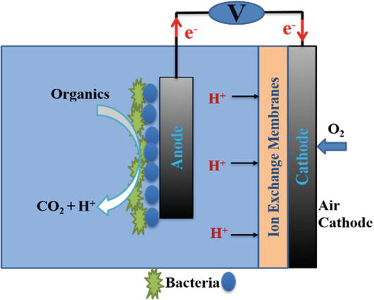
Figure 2.
Air-cathode microbial fuel cell.
In this microbial fuel cell, fabric carbon is usually used to make cathode and anode electrodes. Its ion exchange membrane is Nafion 117 membrane. Its output power using urban sewage as a substrate has been reported as 3.7 W/m3 [31].
In 2004, Liu and his colleagues invented a structure for single-compartment microbial fuel cells that could be used continuously. This structure consisted of two concentric cylinders made of acrylic. There were holes in the central cylinder for contact with air. The cathode electrode, which was made of carbon fabric, was wrapped around the central cylinder. Eight graphite rods were used as the anode electrode, which surrounded the cathode electrode. They used this structure for the first time to investigate wastewater treatment and generate electricity in continuous mode. This microbial fuel cell reduced COD by 80% and produced 26 MW/m3 of electricity. Its coulombic efficiency was less than 12% [32]. Various schematics are used to design two-chamber MFCs, cylindrical, rectangular, miniature, high flow configuration with cylindrical shape, cylindrical shape with U-shaped chamber are the most famous of them. These designs are dependent on MFC performance and the use of defined chemical media such as glucose or acetate solutions, wastewater or factory distillates. These designs are generally used for laboratory scale studies. An example of a single-chamber microbial fuel cell is shown in Figure 3.
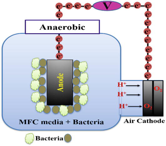
Figure 3.
An example of a single-chamber microbial fuel cell.
3. Power density in microbial fuel cell
A criterion for measuring the efficiency of a microbial fuel cell is CE (coulombic efficiency), which is a measure of the number of coulombs recovered as a comparison of the electric current with the maximum theoretical number of coulombs, which is defined as follows:
where Cp is the total coulombs calculated by summing the flow over time for lactate consumption, and CT is the theoretical amount of coulombs that can be produced from lactate metabolism, which is calculated as follows:
where F is Faraday’s constant (96,485 C/mol-electron), b represents the number of moles of electrons produced by the conversion of lactate to acetate (b = 4) or CO2 and H2O (b = 12) and
In order to obtain the highest theoretical amount of energy and removal rate from a fuel (input material), that reactant must be completely oxidized by the relevant microorganisms and converted into carbon dioxide, and its electrons transferred to the electrode. Without oxidation of the fuel, energy leaves the system through unoxidized fuel. For example, the material of Shewanella oneidenss does not completely decompose the lactate reactant and the electron leaving efficiency of this system is low and its CE is around 56.2% [34]. According to studies, the more capable the microorganisms are in fuel oxidation and complete conversion to 2CO, the higher CE is obtained [35]. Bacteria in which high percentages of CE have been reported are:
CE = 94%, Foracetate Grothrix fermentans, [36], Geobacter species has a CE of about 100% for acetate and 83% for glucose, [37] and the highest CE reported for wastewater was between 65% and 89% [38].
The power density produced by a particular microorganism cannot be compared to that of other microorganisms unless the MFC structure, operating conditions, nutrients, and chemical solutions used for the study are considered identical.
The overall performance of an MFC is evaluated in various ways, but mainly through power output and coulombic efficiency. Power is calculated as follows:
where the voltage is usually measured across a fixed external resistor, while the current is calculated from Ohm’s law (I = Ecell/Rext)). Therefore, power is usually calculated as follows:
It is a direct measurement of electrical power. The maximum power is calculated from the polarization curve. The power density is often normalized to some reactor characteristic so that the power output can be compared in different systems. The choice of parameter to use for normalization depends on the application, as many systems are not optimized for power generation. The output power is usually normalized to the predicted anode surface because the anode is where the biological reaction occurs. Therefore, the power density is calculated based on the anode area:
where
The projected surface area of all components as well as the specific surface area and the method of its determination should always be clearly stated.
To make engineering calculations for the size and cost of reactors, and as a useful comparison to chemical fuel cells, power is normalized to reactor volume or
where Pv is volumetric power (W/m3) and v is the total volume of the reactor. Using the total bed reactor volume is consistent with the engineering tradition of using the total reactor size as the basis for the calculation. However, the comparison based on total reactor volume is not always the same when comparing double and single-chamber reactors because there is no “second chamber” for the open-air cathode. In such cases, it is useful to compare reactors based on the total volume of the anode compartment. If several reactors operate in unison, for example, a series of stack reactors, the volume used for air space for the cathode is included in the total reactor volume. Therefore, the volume used in the calculation should be clearly stated and the volume of individual rooms should always be clearly stated [24].
The power density diagram that describes the power based on the current is calculated from the polarization curve and the relationship (
4. Conclusion
In this chapter, factors affecting fuel cell performance including temperature, pH effect, external resistance, type of electrode, size and distance of electrodes, type and composition of microorganisms, shape, structure, and size of the chamber as well as the importance of power density in microbial fuel cell are investigated. Because determining the importance of these factors cannot be evaluated, therefore, in the design of the microbial fuel cell, the optimal amount should be extracted from the studies and considered in the design of the fuel cell.
References
- 1.
Shirpay A. Bioelectricity generation from human urine in microbial fuel cells: Investigation the effect of additives to urea electrolyte. Biomass Conversion and Biorefinery. 2023:1-2 - 2.
Chandra R, Castillo-Zacarias C, Mancera-Andrade EI, Mohan SV, Parra-Saldívar R. Fundamentals of biophotovoltaics for conversion of solar energy to bioelectricity. In: Microbial Electrochemical Technology. Elsevier; 2019. pp. 503-523 - 3.
Shukla A, Suresh P, Berchmans S, Rajendran A. Biological fuel cells and their applications. Current Science. 2004; 87 (4):455-468 - 4.
He Z, Angenent LT. Application of bacterial biocathodes in microbial fuel cells. Electroanalysis: An International Journal Devoted to Fundamental and Practical Aspects of Electroanalysis. 2006; 18 (19–20):2009-2015 - 5.
Jafari M, Sedighi KS. Microbial fuel cell: A strategy for bioremediation and energy production. Journal of Environmental Science and Technology. 2018; 20 (3):37-43 - 6.
Bazina N, Ahmed TG, Almdaaf M, Jibia S, Sarker M. Power generation from wastewater using microbial fuel cells: A review. Journal of Biotechnology. 2023; 374 :17-30 - 7.
Mishra B, Awasthi SK, Rajak RK. A review on electrical behavior of different substrates, electrodes and membranes in microbial fuel cell. International Journal of Energy Power Engineering. 2017; 11 (9):983-988 - 8.
Lotfi M, Younesi H, Bahramifar N. Wastewater treatment using dual-chamber microbial fuel cell with saccharomyces cerevisiae. Journal of Water and Wastewater. 2018; 29 (4):101-108 - 9.
Kumar R, Singh L, Wahid ZA. Role of microorganisms in microbial fuel cells for bioelectricity production. Microbial Factories: Biofuels, Waste treatment. 2015; 1 :135-154 - 10.
Song HL, Zhu Y, Li J. Electron transfer mechanisms, characteristics and applications of biological cathode microbial fuel cells–a mini review. Arabian Journal of Chemistry. 2019; 12 (8):2236-2243 - 11.
Liu Y, Climent V, Berna A, Feliu JM. Effect of temperature on the catalytic ability of electrochemically active biofilm as anode catalyst in microbial fuel cells. Electroanalysis. 2011; 23 (2):387-394 - 12.
Larrosa-Guerrero A, Scott K, Head IM, Mateo F, Ginesta A, Godinez C. Effect of temperature on the performance of microbial fuel cells. Fuel. 2010; 89 (12):3985-3994 - 13.
Cheng S, Liu H, Logan BE. Increased power generation in a continuous flow MFC with advective flow through the porous anode and reduced electrode spacing. Environmental Science & Technology. 2006; 40 (7):2426-2432 - 14.
Rismani-Yazdi H, Christy AD, Carver SM, Yu Z, Dehority BA, Tuovinen OH. Effect of external resistance on bacterial diversity and metabolism in cellulose-fed microbial fuel cells. Bioresource Technology. 2011; 102 (1):278-283 - 15.
Katuri KP, Enright A-M, O'Flaherty V, Leech D. Microbial analysis of anodic biofilm in a microbial fuel cell using slaughterhouse wastewater. Bioelectrochemistry. 2012; 87 :164-171 - 16.
Sonawane JM, Yadav A, Ghosh PC, Adeloju SB. Recent advances in the development and utilization of modern anode materials for high performance microbial fuel cells. Biosensors and Bioelectronics. 2017; 90 :558-576 - 17.
Du Q, An J, Li J, Zhou L, Li N, Wang X. Polydopamine as a new modification material to accelerate startup and promote anode performance in microbial fuel cells. Journal of Power Sources. 2017; 343 :477-482 - 18.
Liang Y, Feng H, Shen D, Li N, Guo K, Zhou Y, et al. Enhancement of anodic biofilm formation and current output in microbial fuel cells by composite modification of stainless steel electrodes. Journal of Power Sources. 2017; 342 :98-104 - 19.
Santoro C, Arbizzani C, Erable B, Ieropoulos I. Microbial fuel cells: From fundamentals to applications. A review. Journal of Power Sources. 2017; 356 :225-244 - 20.
Gerber M. The Effect of Anode Geometry on Power Output in Microbial Fuel Cells [Dissertation]. Columbus: The Ohio State University; 2014 - 21.
Fernando E, Keshavarz T, Kyazze G. Complete degradation of the azo dye acid Orange-7 and bioelectricity generation in an integrated microbial fuel cell, aerobic two-stage bioreactor system in continuous flow mode at ambient temperature. Bioresource Technology. 2014; 156 :155-162 - 22.
Logan BE. Microbial fuel cells. Hoboken: John Wiley & Sons; 2008 - 23.
Chaudhuri SK, Lovley DR. Electricity generation by direct oxidation of glucose in mediatorless microbial fuel cells. Nature Biotechnology. 2003; 21 (10):1229 - 24.
Logan BE, Hamelers B, Rozendal R, Schröder U, Keller J, Freguia S, et al. Microbial fuel cells: Methodology and technology. Environmental Science & Technology. 2006; 40 (17):5181-5192 - 25.
Shirpay A. Effects of electrode size on the power generation of the microbial fuel cell by Saccharomyces cerevisiae. Ionics. 2021; 27 (9):3967-3973 - 26.
Wang Y, Jiang Y, Guo D-p, Luo S, Wang X-b, Li Y-F. The influence of the electrode anode sizes of the microbial fuel cell (MFC) on the electrical property and COD removal with the electroplating wastewater to be the cathode. Advanced Materials Research. 2010; 113-116 :2189-2192. DOI: 10.4028/www.scientific.net/AMR.113-116.2189 - 27.
Im S-W, Lee H-J, Chung J-W, Ahn Y-T. The effect of electrode spacing and size on the performance of soil microbial fuel cells (SMFC). Journal of Korean Society of Environmental Engineers. 2014; 36 (11):758-763. DOI: 10.4491/KSEE.2014.36.11.758 - 28.
Zuraidah R, Nur SMA, Syazwan M, Ghazali M, Norilhamiah Y, Aida SA, et al. Microbial fuel cell for conversion of chemical energy to electrical energy from food industry wastewater. Journal of Environmental Science and Technology. 2016; 9 (6):481-485 - 29.
Penteado ED, Fernandez-Marchante CM, Zaiat M, Gonzalez ER, Rodrigo MA. Optimization of the performance of a microbial fuel cell using the ratio electrode-surface area/anode-compartment volume. Brazilian Journal of Chemical Engineering. 2018; 35 :141-146. DOI: 10.1590/0104-6632.20180351s20160411 - 30.
Konovalova EY, Stom DI, Zhdanova GO, Yuriev DA, Li Y, Barbora L, et al. The microorganisms used for working in microbial fuel cells. In: AIP Conference Proceedings. Vol. 1952, No. 1. AIP Publishing LLC; 2018. p. 020017 - 31.
Liu H, Logan B. Electricity generation using an air-cathode single chamber microbial fuel cell (MFC) in the absence of a proton exchange membrane. ACS National Meeting Book of Abstracts. 2004; 228 (1):4040-4046 - 32.
Liu H, Cheng S, Huang L, Logan BE. Scale-up of membrane-free single-chamber microbial fuel cells. Journal of Power Sources. 2008; 179 (1):274-279 - 33.
Ringeisen BR, Henderson E, Wu PK, Pietron J, Ray R, Little B, et al. High power density from a miniature microbial fuel cell using Shewanella oneidensis DSP10. Environmental Science & Technology. 2006; 40 (8):2629-2634 - 34.
Lanthier M, Gregory KB, Lovley DR. Growth with high planktonic biomass in Shewanella oneidensis fuel cells. FEMS Microbiology Letters. 2008; 278 :29-35 - 35.
Franks AE, Nevin KP. Microbial fuel cells, a current review. Energies. 2010; 3 (5):899-919 - 36.
Bond DR, Lovley DR. Evidence for involvement of an electron shuttle in electricity generation by Geothrix fermentans. Applied and Environmental Microbiology. 2005; 71 :2186-2189 - 37.
Nevin KP, Richter H, Covalla SF, Johnson JP, Woodard TL, Orloff AL, et al. Power output and columbic efficiencies from biofilms of Geobacter sulfurreducens comparable to mixed community microbial fuel cells. Environmental Microbiology. 2008; 10 :2505-2514 - 38.
Rabaey K, Lissens G, Siciliano SD, Verstraete W. A microbial fuel cell cabable lf converting glucose to electricity at high rate and efficiency. Biotechnology Letters. 2003; 25 :1531-1535