Open Access is an initiative that aims to make scientific research freely available to all. To date our community has made over 100 million downloads. It’s based on principles of collaboration, unobstructed discovery, and, most importantly, scientific progression. As PhD students, we found it difficult to access the research we needed, so we decided to create a new Open Access publisher that levels the playing field for scientists across the world. How? By making research easy to access, and puts the academic needs of the researchers before the business interests of publishers.
We are a community of more than 103,000 authors and editors from 3,291 institutions spanning 160 countries, including Nobel Prize winners and some of the world’s most-cited researchers. Publishing on IntechOpen allows authors to earn citations and find new collaborators, meaning more people see your work not only from your own field of study, but from other related fields too.
This chapter explores the application and benefits of cerium compounds in LEDs, delving into their impact on photoluminescence, electroluminescence, quantum efficiency, and color quality. Cerium compounds (CeO2) play a crucial role in enhancing the efficiency of LEDs. Phosphors are substances that absorb photons and emit light of different wavelengths. By introducing cerium compounds as phosphors in LEDs, the conversion of blue light to other colors becomes more efficient, resulting in improved luminous efficacy. In this chapter, the study on YAG:Ce phosphor material shows that vacuum annealing tends to suppress Ce3+ oxidation more than air annealing, leading to a considerable 20% increase in photoluminescence emission intensity. The optimized YAG:Ce nanoparticles were used to create a white light emitting diode (WLED) that produced cool-white light with a maximum radiation luminous efficacy of 285 lm/W and a comparable color rendering index of 83. Furthermore, Na2MgSiO4:Ce3+:Li+ phosphor study displays tunable emission color characteristics when the content of Ce3+ is increased or Li+ is added as a charge compensator. The utilization of cerium compounds (CeO2) has demonstrated significant efficiency and color quality improvements on YAG:Ce and Na2MgSiO4:Ce3+:Li+ phosphor components.
Department of Physics, University of Johannesburg, Doornfontein, South Africa
Leelakhrishna Reddy
Department of Physics, University of Johannesburg, Doornfontein, South Africa
*Address all correspondence to: letswalom@uj.ac.za
1. Introduction
Cerium compounds are a fascinating material class with unique optical and luminescent properties. These compounds contain the element cerium and have garnered significant interest in scientific research due to their wide range of applications in various fields. In this chapter, we will briefly overview cerium compounds and delve into the importance of their optical and luminescent properties.
1.1 Overview of cerium compounds
Cerium is a rare-earth metal with many industrial applications, making it valuable. Cerium compounds slowly react with water, and commercial-grade cerium has an iron-gray coloration and is as ductile as tin when in its pure form [1]. As the most abundant rare-earth metal, cerium oxidizes in air at room temperature to form CeO2 [1]. Cerium compounds have industrial significance and are used in mantles of lanterns, ceramic, photographic, and textile industries, as well as in analytical chemistry [1]. Cerium oxide (CeO2) have oxygen storage capacities, optical properties, and catalytic properties that make them highly useful, and they have been investigated as an oxygen scavenger in biological systems in drugs and pharmaceutical preparations [2]. CeO2 NPs have various industrial applications, including use as a polishing agent, ultraviolet absorbing compound, solid electrolytes, fuel additive, luminescence and automotive exhaust catalyst [2]. Cerium exists in two main oxidation states, Ce (III) and Ce (IV), with the latter being the only lanthanide that has important aqueous and coordination chemistry in the +4-oxidation state [3, 4]. Ceria is used in chemical-mechanical planarization (CMP) for polishing [4]. However, cerium metal reacts slowly with water and quickly dissolves in diluted acids except hydrofluoric acid [5]. Cerium is a moderately strong paramagnet that becomes antiferromagnetic below 13 K and becomes superconducting in the millikelvin range at pressures exceeding 20 kbar [5]. Cerium is not toxic when eaten, animals injected with large doses of cerium have died due to cardiovascular collapse, and it is a rare-earth metal with low to moderate toxicity [4]. Cerium is a strong reducing agent and ignites spontaneously in air at 65 to 80°C, and fumes from cerium fires are toxic [4]. Ultimately, cerium has many industrial applications, including use in petroleum cracking catalysts, three-way automotive emission catalysts, and ferrous alloys used to scavenge sulfur and oxygen and to nodulize cast iron [5].
1.2 The significance of optical and luminescent properties of cerium compounds in scientific
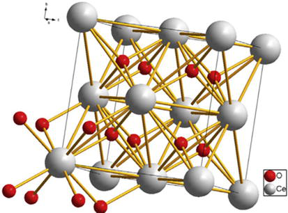
Cerium compounds have been extensively studied in scientific research and various industrial applications due to their remarkable optical and luminescent properties. A study was conducted to investigate the optical and scintillation properties of cerium-doped lanthanide trihalides, aimed at gaining a better understanding of the scintillation process in this trihalide series [6]. The study reported emission and excitation spectra, X-ray induced emission spectra, pulse-height measurements, and scintillation decay time spectra. The fluorescence spectra exhibited structure at low temperatures, while garnet crystals showing luminescence exhibited bright-yellow fluorescence [6, 7]. Cerium-activated garnet crystals exhibited luminescence, while the wavelength maxima of the fluorescence-spectrum profiles were found to be host-dependent [7]. Additionally, the direct bandgap of cerium oxide falls in the 3.2–3.6 eV range, while the indirect bandgap falls between 2.9–3.3 eV [8]. Cerium oxide have excellent optical properties, making them useful for electro-optical and optoelectronic devices [8]. Ce3+ ion is an important activator whose excitation and emission are based on the transition between its 4f ground levels and 5d excited levels. The energy of 5d levels of Ce3+ relative to 4f ground state depends on its coordination environment that relies on the host structure. According to this feature, broadband emission with different colors can be achieved through the adjustment of the host structure. Therefore, the activator generally has a similar ionic radius and charge to the substituted ion. The crystal cubic fluorite-type of space group Fm-3 m structure of the CeO2 compound is presented in Figure 1 [6, 7, 8].
Figure 1.
Visualization of the crystal CeO2 structure with the cubic space group of Fm-3 m (225), (ICDD – 43-1002).
Various methods have been developed to produce nanostructured materials from gas, liquid, or solid phases. In recent years, materials such as cerium compounds have been used to produce nanostructures as a host (base) or activator and we discuss some synthesis methods below [9, 10].
2.1 Combustion synthesis of nanocrystalline CeO2-based powders via ethylene glycol: Nitrate process
In accordance with the specified ethylene glycol-nitrate ratios, precise quantities of cerium nitrate (Ce(NO3)3•6H2O 99.5%) and ethylene glycol (99%) were meticulously blended in deionized water, ensuring the production of transparent solutions. These solutions were subsequently evaporated in an insulated tall beaker placed on a hot plate at a temperature of 105°C. Moreover, a proportion of the transparent solutions underwent additional drying in an oven at the same temperature for a duration of 24 hours, resulting in the formation of a gel precursor employed for TGA-DSC analysis. Once the viscous liquids took shape, a finely woven lid was securely positioned on the beaker to capture the ensuing powder during the ensuing autoignition process. Concurrently, the temperature of the hot plate was elevated to 250°C, leading to the expansion and autoignition of the viscous liquids, ultimately culminating in the rapid discharge of a substantial volume of gases and the eventual formation of voluminous powders. To obtain pure and well-crystallized ceria powders, the powders obtained post-autoignition were subjected to calcination at 500°C for a duration of 2 hours utilizing a muffle furnace. Subsequently, the calcined powders were milled for 6 hours in ethanol utilizing a planetary mill rotating at a rate of 350 r/min. They were subsequently dried and further pulverized in a mortar [9].
2.2 Synthesis of cerium(IV) oxide ultrafine particles by solid-state reactions
For the experimental procedure, a number of chemicals were utilized, specifically AR-grade ammonium cerium (IV) nitrate [(NH4)2Ce(NO3)6], cerium(III) nitrate hexahydrate [Ce(NO3)3z6H2O], sodium hydroxide (NaOH), and anhydrous ethanol (C2H5OH). To obtain ultrafine particles of CeO2, a mixture of (NH4)2Ce(NO3)6 (0.01 mol, 5.48 g) and NaOH (0.06 mol, 2.40 g) was initially combined and ground at room temperature for 30 minutes under normal air conditions. The resulting mixture was then suspended in distilled water and underwent 10 minutes of ultrasound treatment. Subsequently, the solid product was subjected to centrifugation for 10 minutes at 8000 rpm. This washing procedure was repeated using 80 mL of distilled water until the solution’s pH dropped below 8. Afterwards, the product was washed twice with 40 mL of ethanol, dried in air, and yielded CeO2 ultrafine particles weighing 1.69 g, with a 98% yield. A portion of the obtained solid CeO2 (approximately 0.25 g) was then sintered at various temperatures ranging from room temperature to 800°C for a duration of 2 hours in the presence of air. Additionally, Ce(NO3)3z6H2O (0.01 mol, 4.34 g) and NaOH (0.03 mol, 1.20 g) underwent a similar reaction to produce CeO2 ultrafine particles [10].
Below are synthesis methods where cerium compounds are commonly used as activators.
2.3 Solid state method
The MgB4O7 powders were prepared by the solid-state synthesis method. MgO (Merck, 99.9% purity) and H3BO3 (Merck, 99.9% purity) were selected as starting reactants. The synthesis process began with mixing certain amounts of MgO and H3BO3 in an agate mortar and grinding until a homogeneous mixture was obtained. After the grinding operations, the mixture was calcined in an ash kiln at 850°C for 6 hours. The Ce dopant was selected in oxide form cerium oxide (CeO2, Merck, powder, 99.995%) and added to the mixture in different weight ratios. The dopant-containing mixture was ground again and calcined the next time at 850°C for 6 hours [11, 12].
2.4 Solution combustion method
MgB4O7 was synthesized by solution combustion synthesis (SCS). This method combines a metal nitrate, fuel and other precursors in water and heats the mixture until combustion, producing a form of fine particles of the product. In the case of MBO, magnesium nitrate hexahydrate, boric acid, nitrates of the desired dopants (mainly LiNO3 and Ce(NO3)3) and urea are mixed. An excess of boric acid is required to obtain the desired MgB4O7 crystal phase. In addition, the use of high-purity reagents to improve the material was investigated. After synthesis, annealing is required to crystallize the material fully: samples were heated to 900°C at 5°C/min and soaked for 2 h at the selected annealing temperature and let it cool down [13, 14].
The optical absorption spectrum of phosphor materials was recorded using a Perkin Elmer UV-Vis spectrophotometer at room temperature. The photoluminescence (PL) and lifetime measurements were carried out in a spectro-fluorometer with a xenon lamp as an excitation source.
3.1 Optical properties of Ce based MgB4O7 compounds
Band gap energy, often simply called band gap, is a fundamental concept in solid state physics and materials science. It is a key property that characterizes the electronic structure of semiconductors and insulators. The band gap represents the energy difference between the valence band and the conduction band in the electronic band structure of the material. The size of the band gap determines the electrical properties of the material. Bandgap energy is a key property when selecting materials for specific applications in electronics, photonics and optoelectronics. Different materials have different bandgap energies, and engineers and scientists choose materials with an appropriate bandgap for their desired function. It is a basic property that characterizes materials’ electrical conductivity and optical properties [15].
Materials with a band gap larger than the energy of visible light (typically 1.65 to 3.1 eV) are transparent to visible light. A material’s color depends on the energy of the absorbed light, which corresponds to the energy of the band gap. This energy threshold has several important implications for a material’s interaction with light, such as its transparency, color and ability to absorb or emit photons [16].
Bandgap energy analysis of cerium (Ce) compounds involves studying these materials’ electronic structure and properties. Cerium is a rare earth element that can form a variety of compounds with different band gap energies, depending on the specific compound and its crystal structure. For example, analysis of the bandgap energy of cerium compounds involves a combination of theoretical calculations, experimental measurements, crystal structure analysis, and an understanding of the compound’s intended application. The energy of the bandgap determines the wavelength of light that a semiconductor can emit or absorb. For example, in light-emitting diodes (LEDs), the bandgap energy determines the color of the light produced. Different materials with different bandgap energies can be used to make LEDs of different colors [16, 17, 18, 19].
3.2 Excitation spectrum
An excitation spectrum is a graphical representation of how the absorption or excitation of a substance changes with the wavelength or energy of the incident light. In an excitation process, a substance is exposed to light and can absorb photons whose energies correspond to the energy levels or transitions within the substance. This absorption causes electrons to move into higher energy states or orbitals.
3.3 Emission spectrum
An emission spectrum is a graphical representation of the light emitted by a substance as it returns to lower energy states after excitation and shows the emitted photons. As the substance returns to its lower energy state, it releases energy in the form of photons. These emitted photons have energies corresponding to the energy levels or transitions involved in the de-excitation process.
3.4 Relationship
The emission lines in the emission spectrum correspond to the same energy levels or transitions observed in the excitation spectrum. This correspondence is a fundamental aspect of the Kasha-Vavilov rule, which states that the emission energy (wavelength) in a photoluminescence process should be independent of the excitation wavelength. It allows researchers to identify the specific energy levels and transitions that play a role in the luminescence behavior of cerium compounds [20].
The excitation and emission spectra of a material are influenced by various factors, including the material’s electronic structure, chemical composition, physical state, and external conditions. The main key factors that can influence the excitation and emission spectra are chemical compositions, crystal structures, dopant/impurities, pressure, chemical environment temperature, concentration, excitation source, molecular structure, etc., [21].
These factors are essential in studying the excitation and Emission spectra of materials. Researchers often manipulate these factors to develop and optimize materials for various applications, including fluorescence, phosphorescence, laser operation, and optoelectronic devices [22].
4.1 Impact of doping of cerium compound with other elements that influences its optical and luminescent properties
Doped cerium compounds have been intentionally mixed with other elements or molecules. For instance, by doping cerium compounds with specific rare earth elements, researchers can fine-tune the emission spectra of LEDs, expanding the range of available colors. Additionally, doped cerium compounds can enhance the stability and longevity of LEDs. By carefully selecting dopants, manufacturers can mitigate issues such as color shift and degradation of performance over time, ensuring the longevity and reliability of LED lighting systems.
4.2 Luminescent properties of various host materials doped with cerium compound
4.2.1 Definition of photoluminescence
Photoluminescence is defined as the emission of light from a material upon its absorption of photons. In the case of cerium compounds, this phenomenon occurs due to the excitation of electrons in the outermost orbitals of the cerium ions. Upon absorption of photons, these electrons gain energy and are promoted to higher energy levels, leaving behind holes in the lower energy levels. Subsequently, the recombination of electrons and holes leads to the emission of light. Below, the process of the photoluminescence mechanism and the analysis of the emission spectra of different host material doped cerium compounds as an activator.
4.2.2 Electroluminescence properties
Electroluminescence, on the other hand, is the emission of light from a material upon applying an electric field. Cerium compounds have demonstrated promising properties in electroluminescent devices. These compounds can be incorporated into phosphors, such as organic light-emitting diodes (OLEDs), to create efficient and customizable sources of light. The advantageous characteristics of cerium compounds in electroluminescence applications include their high luminous efficiency, broad emission spectra, and long operational lifetimes. These compounds can be easily tailored to emit light across a wide range of colors, making them suitable for various display applications. However, it is crucial to acknowledge the limitations of cerium compounds in electroluminescence applications. The use of cerium compounds as an activator in electroluminescent devices—where the cerium compound is doped to the host material—has been investigated below.
4.2.3 Quantum efficiency of cerium compound
Quantum efficiency is a measure of the efficiency with which a material converts absorbed photons into emitted photons. Evaluating the quantum efficiency of cerium compounds is crucial to assessing their performance relative to other luminescent materials. Several factors, including the purity of the compound, defects or impurities present, and the electronic structure of the host lattice, influence the quantum efficiency of cerium compounds.
Comparative studies below have revealed that cerium compounds exhibit competitive quantum efficiency when compared to other luminescent materials. Their unique energy levels and electron configurations allow for excellent photon conversion efficiency. This characteristic, coupled with their advantageous photoluminescence and electroluminescence properties, positions cerium compounds as promising candidates for various applications in the field of luminescent materials.
5. Photoluminescence properties of YAG are doped with a cerium compound (Ce3+ ion)
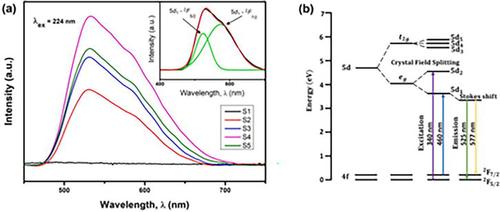
The PL emission spectra of the annealed and as-combusted YAG:Ce NPs are displayed in Figure 2 at 224 nm. Without an ordered crystalline structure, the activator was unable to integrate into the crystal lattice, which prevented the formation of a luminescent center necessary for optical transition. The d-f emission was typically composed of double structures that made up the characteristic long wavelength emission because of the strong crystal field applied to the dodecahedral site in the YAG structure where the Ce3+ ions are located. In the emission band, a double Gaussian function with an energy difference of roughly 1923 cm−1 was deconvoluted from the 5d1 → 2F(5/2) (525 nm) and 5d1 → 2F(7/2) (577 nm) transitions of the Ce3+ ion, as shown in Figure 2(a) insert. The schematic illustration presented in Figure 2b provides insight into the optical transition mechanism for the Ce3+ion in garnet crystal structure [24, 25].
Figure 2.
PL emission spectra for the as-combusted and different annealing treated YAG:Ce NPs (a) and schematic diagram of the electronic level structure of Ce3+ in YAG lattice [23]. The inset of (a) shows the deconvoluted emission band for YAG:Ce NPs.
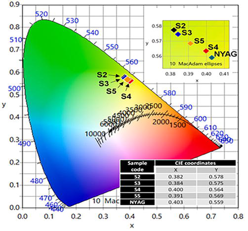
Additionally, the Commission internationale de I’Eclairage (CIE) chromaticity diagram was used to visualize the variation in emission properties for the YAG:Ce NPs under investigation. The CIE color coordinates of the samples, as shown in Figure 3, are in the greenish-yellow region, which is consistent with the emission color characteristic of YAG:Ce phosphor. It should be noted that S4 color coordinates were extremely similar to those of commercial YAG: Ce (NYAG4056-01-1, Intematix), indicating the usefulness of the synthesized phosphor. A notable observation was the linear shift in CIE color coordinates towards the deeper yellow region with an increase in CIE x and a decrease in CIE y coordinates. This shift is probably caused by the red component being more enriched from the broadened FWHM of the PL emission band. The ground state may not have fully split, resulting in a smaller energy difference between the 4f1 and 5d, as the PL emission FWHM narrowed with decreasing powder crystallinity [25, 26]. In addition, for noting: a.u. on the spectrum represent Arbitrary Scale (represented as arb. Units or a.u.).
Figure 3.
CIE chromaticity diagram for different annealing treated YAG:Ce NPs and commercial NYAG. The inset shows the enlarged view on the CIE coordinates for each sample.
5.1 Electroluminescence properties of YAG doped with cerium compound (Ce3+ ion)
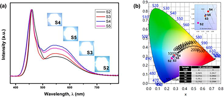
To evaluate the suitability of the WLEDs made from various annealing-treated YAG:Ce NPs as white light emitters, photometric measurements were carried out on the devices. The obtained result was consistent with the PL analysis, indicating that enhanced powder crystallinity and stronger Ce3+ incorporation worked together to produce higher yellow fluorescence, which was the cause of the increasing tendency. Furthermore, S5 amply demonstrated the negative impact of cerium oxidation (Ce3+ → Ce4+), as the concentration of optically inert Ce4+ ions increased and consequently, the intensity of the yellow emission decreased. Consequently, the CIE chromaticity diagram (Figure 4b) was used to plot the corresponding CIE color coordinates to represent the variations in the EL spectra of the WLEDs. For S2, the color coordinates were first placed in the bluish-white area. For S3, S5, and S4, the color coordinates moved linearly in the direction of the ideal white illumination (0.333, 0.333) along the blackbody locus. The results, which display a shift in color from bluish white to light cool-white, are in good agreement with the images captured on WLEDs. Following measurements, Table 1 presents the results of the luminous efficacy of radiation (LER), purity, correlated color temperature (CCT), and color rendering index (CRI).
Figure 4.
EL spectra (a) and CIE coordinates (b) for the packaged WLEDs under a forward bias current of 20 mA. The inset of (a) and (b) each showed the photographic image of working WLEDs and a section of the 1931 CIE diagram, respectively.
Sample code
CCT (Kelvin, K)
CRI
Purity %
LER (lumen/watt, lm/w)
S2
13,370
79
29.12
261
S3
10,152
81
22.81
278
S4
9142
83
20.00
285
S5
9918
83
22.2
279
Table 1.
EL parameters of WLEDs fabricated with different annealing treated YAG:Ce NPs.
The outcome was a manifestation of higher yellow light output due to increased absorption of blue light, bringing the light output closer to the ideal white illumination. The S5 WLED’s CRI, on the other hand, was comparable to the S4’s, but because of the former’s reduced yellow-to-blue light ratio, its CCT has significantly increased. Moreover, it was crucial to maintain the WLED’s color purity at a minimum achievable value of 0.1 for perfect white illumination. Table 1 shows that, among the fabricated samples, S4 WLED with the lowest purity indicated the highest optical quality based on its color coordinates that were closest to the ideal white illumination. The degree to which the phosphor emission spectrum satisfies the sensitivity of the human eye is indicated by the luminous efficacy of radiation (LER) [27].
6. Photoluminescence properties of NMSO doped with cerium compound (Ce3+ ion)
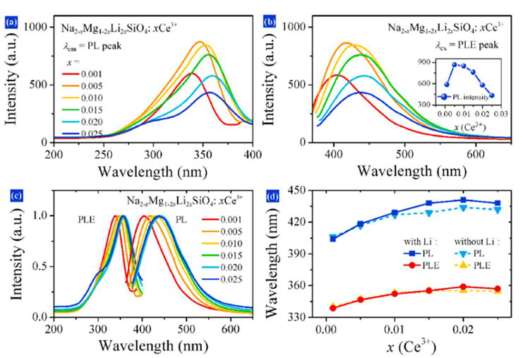
The PLE spectra of the phosphors NMSO:xCe3+ that are monitored using the emission peak value are displayed in Figure 5a. The PL spectra of the phosphors excited by the excitation peak value are displayed in Figure 5b. The findings show that when near-UV light is applied to the phosphors, they display an asymmetric blue emission band. Because of the spin-orbit coupling of the 4f energy level and the 5d-4f transition, the asymmetric emission band is typical for Ce3+ doped phosphors.
Figure 5.
(a) PLE spectra of Na2-xMg1-2xLi2xSiO4:X Ce3+; (b) PL spectrogram, inset: The variation trend of PL peak with Ce3+ content (x); (c) normalized PL and PLE spectra; (d) the variation trend of PL and PLE peak values with Ce3+ content.
The emission intensity and Ce3+ content are plotted in Figure 5b. From 0.001 to 0.005, the intensity rises with Ce3+ content before falling as the content rises even higher. Emission intensity is highest for NMSO:0.005 Ce3+. The positions of the excitation and emission bands shift along with the increase in Ce3+ content, as does the emission intensity. As the Ce3+ content rises, there is a red shift seen in both the PLE and PL peaks. Figure 5c normalized excitation and emission spectra make it evident how the PLE and PL bands change as the Ce3+ content rises.
The PLE and PL peak values as a function of the Ce3+ content are also displayed in Figure 5d. As the Ce3+ content rises from 0.001 to 0.020, the excitation peak shifts from 339 to 356 nm and the emission band shifts from 404 to 441 nm. For x = 0.025, there is also a slight blue shift of the PLE and PL bands. Figure S3 displays the PLE and PL spectra of Na2-xMgSiO4:x Ce3+ for comparison. As the Ce3+ content increases, a red shift of the excitation and emission bands is also seen in Na2-xMgSiO4:x Ce3+.
As shown in Figure 5d, the red shift’s extent is, nevertheless, less than that of NMSO:x Ce3+ with Li+. In addition to the asymmetric blue emission band, a shoulder is present at roughly 500 nm. The presence of two Na sites is suggested by the presence of a second environment for Ce3+, as indicated by the shoulder at 500 nm.
6.1 Thermal stability and quantum efficiency of the phosphor
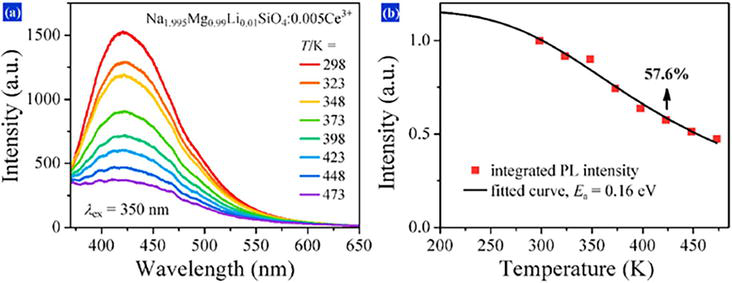
Figure 6a displays the PL spectra of NMSO:0.005 Ce3+ as a function of temperature (excited at 350 nm). It is evident that, as the temperature rises, the sample’s emission intensity progressively drops while the emission peak essentially stays constant. The normalized integrated emission intensity as a function of temperature is displayed in Figure 6b.
Figure 6.
(a) Temperature-dependent PL spectra of NMSO:0.005 Ce3+, (b) normalized integrated luminescence intensity as a function of temperature and fitted curve.
The phosphor at 150°C maintains 57.6% of its intensity at room temperature because of thermal quenching. The data were examined using the Arrhenius equation to determine the relationship between temperature and luminescence intensity.
Figure 6b displays the fitted curve in accordance with. A value of 0.16 eV is the obtained Ea. Furthermore, NMSO:0.005 Ce3+ exhibits an absolute quantum efficiency of 86.0% when excited at 365 nm; corresponding spectra are displayed in Figure S5. The phosphor’s efficiency and thermal stability imply that it is appropriate for use with PC-LEDs.
6.2 Electroluminescence properties of YAG doped with cerium compound (Ce3+ ion)
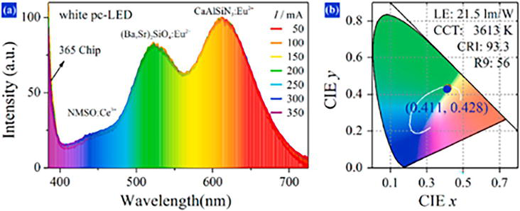
To assess the phosphors’ potential for use, a 365 nm UV LED chip is assembled with commercial green-emitting (BaSr)2SiO4:Eu2+, red-emitting CaAlSiN3:Eu2+, and NMSO:0.005 Ce3+ to create a white-emitting pc-LED. The electroluminescence (EL) spectra of a white PC-LED driven by various forward bias currents (50–350 mA) are displayed in Figure 7a. The entire visible light spectrum is covered by the EL band, and the normalized EL spectra at various currents almost exactly overlap. As illustrated in Figure 7b, the associated International Commission on Illumination (CIE) coordinates likewise almost overlap.
Figure 7.
(a) EL spectra of white pc-LED driven by different forward bias currents (50–350 mA), (b) parameters of the white pc-LED at 50 mA.
These phenomena imply that the phosphors emission positions are stable. As the working current increases, the temperature of the LED chip rises, a phenomenon that further suggests the thermal stability of the as-synthesized phosphor. The white PC-LEDs CRI value is 93.3 at 50 mA, and Figure 7b lists the PC-LED’s other specifications. Based on these findings, it is possible to use the prepared phosphors as a potential blue-emitting phosphor for white PC-LEDs [28].
In the market today, several types of light-emitting diodes (LEDs) are designed for specific applications. One category is the traditional LEDs, which are primarily composed of inorganic materials. Another category is the Organic Light-Emitting Diodes (OLEDs), which are composed of organic materials. In traditional LEDs, light emission results from the recombination of electrons and holes within the band gap of inorganic materials, while in contrast to LEDs, OLEDs rely on the recombination process within organic materials, leading to the emission of light. In both cases, organic and inorganic materials are dependent on the hosts and dopants used.
7.1 Usage of Ce3+ compounds in LEDs and OLEDs for displays
Cerium-activated phosphor host materials play an integral part in LED lighting technology. This is achieved through the illumination of specific colors via concentration variations or through co-doping with other rare earth ions when excited by UV or blue light. Although the first invention of LED technology produced red light, Ce3+ doped aluminum garnet (YAG: Ce) played a pivotal role in producing white light of a more efficient nature. In particular, the combination of a blue-emitting phosphor and a yellow-emitting YAG: Ce3+ yielded white light of a superior nature [29]. The emission that originates from Ce3+ ion is due to the allowed electric dipole 5d → 4f transition, which produces a broad-band emission [29]. In this instance, when blue light or UV light excites a YAG: Ce3+ phosphor, produces yellow light. A combination of this yellow light with the remaining blue light results in a high-resolution of white light [30]. Basically, the color-correlated temperature (CCT) values change which subsequently produces a range of visible colors, such as different shades of white light (warm or cool), which may be applicable to various environmental settings [31].
On the other hand, the development of OLEDs for use in displays and illumination is a growing market. Lanthanides, specifically Ln3+, are being explored in OLED technology for their sharp emission resulting from 4f-4f transitions [32]. Generally, obtaining blue emissions is a challenge; however, Tm3+ rare-earth ions are common due to their 1G4 → 3H6 transitions, and our common Ce3+ ions are known for their allowed 5d → 4f transition [32]. While blue emissions from Ce3+ ions are rare in OLEDs, ongoing research in this field aims to tailor Ce3+ ions for that purpose. Alternatively, Ce3+ ions are used to excite other compounds [33], contributing to the efficiency of display devices. Research, such as that conducted by [34], demonstrates that Ce3+ ions yield optimal luminescence for a particular concentration. Thus, the use of Ce3+ ions in electroluminescent devices are mainly associated with enhancing organic emitters or exciting phosphors in organic materials through its UV emissions [32].
7.2 Incorporating Ce3+ compounds in energy-efficient lighting systems
Following the blue emissions discussed earlier, the most common method of achieving white light emissions is by combining a blue light-emitting chip, known as the indium gallium nitrate chip (InGaN), with a yellow-emitting phosphor material (Y3Al5O12:Ce3+), comprised of Ce3+ ions as a dopant, to produce the desired white light in lighting systems [35]. Despite these advances, its application remains limited due to low chemical stability and low luminous efficiency. Current research is focused on developing red-emitting phosphors with high luminous efficiency, excellent thermal stability, and high color purity [35] to produce a better quality of white light in display systems.
7.3 Future prospects and improvements in lighting and display systems
Although most single-doped phosphor-converted LEDs (pcLEDs) containing YAG:Ce3+ phosphors are commonly used to generate white light when excited by a blue LED source, this fabrication encounters stability issues due to the absence of the red color component. This limitation hinders the commercial feasibility of such LEDs as sources of white light [36]. This approach is perceived as a trade-off between color retention, Low Correlated Color Temperature (CCT) values, and luminous efficacy [36]. However, the main drawback is the absence of the red spectral component. The resulting white light typically has a CCT value exceeding 4000 K (cool white) and a low CRI (<80) [36]. In certain environments, such as indoor settings, a warm white light WW (2700-3200 K) is more preferred. Future advancements in this regard may involve a two-phosphor fabrication approach to produce white light—a combination of a yellow-emitting (YAG:Ce3+) phosphor and a red-emitting phosphor material [35, 36].
7.4 Solar energy conversion
Solar energy conversion is a ground-breaking technology that harnesses solar power to generate electricity. It offers a sustainable and renewable source of energy, reducing greenhouse gas emissions and dependence on non-renewable resources. Solar energy conversion involves the process of transforming sunlight into usable energy. The primary method utilized for this purpose is by photovoltaic (PV) cells, also known as solar cells. These cells are typically made from semiconductor ma-terials and can convert sunlight into electricity. When sunlight strikes the solar cells, it excites the electrons within the material, causing them to flow and generate an electric current. This direct current (DC) is then converted into alternating current (AC) by an inverter, making it suitable for powering appliances and feeding into the electricity grid [37].
7.5 Role of Ce3+ compounds in solar cells
Ce3+ compounds are also used in the application of solar cells. In this respect, crystalline silicon solar cells (PV module) can be applied to convert solar energy from the sun to electricity [Xue] in alignment of 4 different technologies, namely, down conversion, anti-reflective coatings, enhancement of electron transport properties, and enhanced stability.
Down conversion: To improve the efficiency of silicon solar cells, compounds such as Y2SiO5:Ce3+, Yb3+ are mostly used because Yb3+ is well suited for energy excitation range (10,000 cm−1) from ground state to the highest excited state, which corresponds to NIR emission of around 980 nm [37, 38]. In this compound, it can down-convert an excitation wavelength of 457 nm (blue violet) to 980 nm (NIR). Further, for this sample, Ce3+ can capture a broader range of UV light to cause emission of low energy photons, thereby making the solar cells very adaptable for this type of capture [38]. This process enhances the efficiency of silicon solar cells.
Anti-reflective coatings: CaF2:Ce3+, Yb3+ are excellent luminescent materials that can be used in silicon solar cells as anti-reflective coating materials [37]. The purpose of this is to prevent the reflection of light to avoid damage to silicon materials and maximize efficiency, by using the CaF2 material. For this process, high energy UV photons are converted to NIR photons through dopants (Ce3+, Yb3+) and the protective materials, enhancing efficiency. This allows more photons to penetrate the surface, hereby minimizing energy loss from the material [37].
Enhancement of electron transport properties: In this process, Ce3+-doped inorganic materials, such as SrF2 in dye-sensitized solar cells, are used to convert high-energy photons to low-energy photons in the visible region through a process called down-shifting. This down-shifting process facilitates the transport of electrons, leading to an enhancement of energy and power efficiencies and thereby improving the overall performance of silicon solar cells [39].
Enhanced stability: The enhanced stability of perovskite solar cells can be achieved by doping perovskite materials (MAPbI3) with Ce3+ ions. The doping of Ce3+ ions lead to enhanced stability of the material, arising from the formation of a Ce3+/Ce4+ redox pair and unique absorption in the UV region [40]. This leads to a more durable silicon solar cell that can withstand harsh environmental conditions.
7.6 Improving efficiency and stability of solar cells
Issues such as efficiency (as discussed) and stability are critical considerations for the commercialization of any of the above solar cells. Perovskite solar cells, in particular, have emerged as promising candidates in this regard, offering cost-effective fabrication, optimal performances at low temperatures, and high efficiency as both light absorbers and charge transporters [41]. These solar cells offer more than 20% efficiency, beating the 3rd generation of solar cells in their class. Coating attempts to address these issues often result in higher fabrication costs and make it heavier, thus making it an impractical solution. In an ideal situation, a solar cell should last for over 1000 hours, be stable at high temperatures, and have a lifespan of more than 20 years [41].
7.7 Challenges and future developments of the use of Ce3+ in solar cells
Since weather conditions play a major role in solar cell technology, integrating storage batteries could be advantageous for energy storage in the absence of sunlight [42]. The current global supply of electricity from solar PV generation is about 3%, and the intention is to increase this supply by 13% in 2030 and 25% in 2050 [42]. However, for this to be feasible, solar systems need to be economically viable when taking into consideration that commercially produced solar cells have efficiencies between 12 and 30% [42]. Alternatively, the sun’s energy concentration can be directed to systems where collection of it is then transferred to heat fluids that will produce steam, which would then be able to turn turbines to produce electricity [42]. Ce3+ compounds are leading protagonists in such endeavors because they can collect UV rays and produce visible emissions through down-conversion processes. Such endeavors are achievable provided the efficiencies and stabilities of Ce3+ doped systems are improved.
These cerium compound possess significant potential in display technologies, lighting, and biological imaging applications. Recent research efforts focused on improving quantum efficiency and addressing the limitations associated with cerium compounds will further enhance their effectiveness. There are various synthetic methods that can be utilized to prepare phosphor materials doped with cerium compound such as solid-state reaction and combustion method. In this chapter, the comparison between air annealing and vacuum annealing for YAG:Ce NPs produced by combustion synthesis was observed on YAG:Ce NPs. The increase in PL emission intensity and a greater proportion of Ce3+ were the result of vacuum annealing. With longer annealing times, the NPs’ CIE color coordinates are redshifted. The WLED made using YAG:Ce NPs and vacuum-annealed for five hours had the highest LER of 285 lm/W, according to the EL parameters, because the phosphor fluorescence and photopic curve overlapped more. The WLED emitted cool-white light could be further enhanced by fine-tuning the phosphor and packaging method. Na2MgSiO4:Ce3+ study revealed that a high-temperature solid-state reaction was used to produce the phosphors. The phosphors emit blue light, which shifts the emission band to the longer wavelength side, when the host’s Ce3+ content is increased or Li+ ions are added. The reabsorption effect, energy transfer, and a stronger crystal field are the causes of this. Two Na sites harboring Ce3+ ions are responsible for the broad asymmetric emission band. The phosphor has a respectable level of thermal stability in addition to a high absolute quantum efficiency. The performance of the phosphor as-prepared suggests that PC-LEDs could use it as a possible material for white PC-LEDs.
The authors state that none of the work described in this chapter appears to have been influenced by any known competing financial interests or personal relationships.
Notes/thanks/other declarations
No additional declarations are available for this chapter.
References
1.Cerium Summary. Retrieved December 1, 2023, Available from: www.britannica.com/summary/cerium
2.Cerium. Retrieved December 1, 2023, Available from: www.sciencedirect.com/topics/engineering/cerium
3.Cerium Compounds. Retrieved December 1, 2023, Available from: www.en.wikipedia.org/wiki/Cerium_compounds
4.Cerium. Retrieved December 1, 2023, Available from: www.en.wikipedia.org/wiki/Cerium
5.Cerium. Encyclopædia Britannica, Encyclopædia Britannica, inc., Available from: www.britannica.com/science/cerium [Accessed: December 2, 2023]
6.Optical and Scintillation Properties of Cerium-Doped LaCl3, LuBr3 and LuCl3. Retrieved December 1, 2023, Available from: www.sciencedirect.com
7.Journal of the Optical Society of America. Retrieved December 1, 2023, Available from: www.opg.optica.org/abstract.cfm?uri=josa-59-1-60
8.Cerium Oxide Nanoparticles: Properties, Biosynthesis and Biomedical Application. Retrieved December 1, 2023, Available from: www.ncbi.nlm.nih.gov/pmc/articles/PMC9055511/
9.Mokkelbost T, Kaus I, Grande T, Einarsrud MA. Combustion synthesis and characterization of Nanocrystalline CeO2-based powders. Chemistry of Materials. 2004;16(25):5489-5494
10.Xianghua Y, Li F, Ye X, Xin X. Synthesis of cerium(iv) oxide ultrafine particles by solid-state reactions. Journal of the American Ceramic Society. 2000;83(4):964-966
11.Souza LF, Vidal RM, Souza SO, Souza DN. Thermoluminescent dosimetric comparison for two different MgB4O7: Dy production routes. Radiation Physics and Chemistry. 2014;104:100-103
12.Altunal V, Abusaid W, Guckan V, Ozdemir A, Yegingil Z. Luminescence characterization of Ce and Gd doped MgB4O7 phosphors. Journal of Luminescence. 2022;246:118815
13.Ozdemir A, Altunal VO, Guckan V, Kurt K, Yegingil Z. Luminescence characteristics of newly-developed MgB4O7: Ce3+, Na+ phosphor as an OSL dosimeter. Journal of Alloys and Compounds. 2021;865:158498
14.Santos CC, Valença JV, d’Errico F, Machado R, Caldas LV, Souza SO. Effect of different solvents on the optically stimulated luminescence signal from MgB4O7: Ce. Li-loaded polymer films. Radiation Protection Dosimetry. 2022;198(16):1230-1237
15.Souza LF, Novais AL, Antonio PL, Caldas LV, Souza DN. Luminescent properties of MgB4O7: Ce, Li to be applied in radiation dosimetry. Radiation Physics and Chemistry. 2019;164:108353
16.Souza LF, Silva AM, Antonio PL, Caldas LV, Souza SO, d’Errico F, et al. Dosimetric properties of MgB4O7: Dy, Li and MgB4O7: Ce, Li for optically stimulated luminescence applications. Radiation Measurements. 2017;106:196-199
17.Gustafson TD, Milliken ED, Jacobsohn LG, Yukihara EG. Progress and challenges towards the development of a new optically stimulated luminescence (OSL) material based on MgB4O7: Ce, Li. Journal of Luminescence. 2019;212:242-249
18.Clayton RK. Light and Living Matter: A Guide to the Study of Photobiology. vol. 1: The physical part. 148 Seiten, 55 abb. und 2 tab. vol. 2: The biological part. 242 Seiten, 71 ABB. New York: McGraw-Hill Book Company; 1971. Preis: Vol. 1: 12,40 dm, vol. 2: 16,60 DM. Food / Nahrung. Jan 1972;16(7):810-811. DOI: 10.1002/food.19720160717
19.Quack M. Molecular quantum dynamics from high resolution spectroscopy and laser chemistry. Journal of molecular structure. 1993;292:171-195
20.Li G, Tian Y, Zhao Y, Lin J. Recent progress in luminescence tuning of Ce3+ and Eu2+-activated phosphors for pc-WLEDs. Chemical Society Reviews. 2015;44(23):8688-8713
21.Qin X, Liu X, Huang W, Bettinelli M, Liu X. Lanthanide-activated phosphors based on 4f-5d optical transitions: Theoretical and experimental aspects. Chemical reviews. 2017;117(5):4488-4527
22.Shrestha N, Vandenbroucke D, Leblans P, Yukihara EG. Feasibility studies on the use of MgB4O7: Ce, Li-based films in 2D optically stimulated luminescence dosimetry. Physics Open. 2020;5:100037
23.Liang J, Devakumar B, Sun L, Wang S, Sun Q , Huang X. Full-visible-spectrum lighting enabled by an excellent cyan-emitting garnet phosphor. Journal of Materials Chemistry C. 2020;8(14):4934-4943
24.Guerbous L, Boukerika A. Nanomaterial host bands effect on the photoluminescence properties of Ce-doped YAG nanophosphor synthesized by sol-gel method. Journal of Nanomaterials. 2015;16(1):97-97
25.Xia Z, Meijerink A. Ce3+-doped garnet phosphors: Composition modification, luminescence properties and applications. Chemical Society Reviews. 2017;46(1):275-299
26.Liang J, Sun L, Wang S, Sun Q , Devakumar B, Huang X. Filling the cyan gap toward full-visible-spectrum LED lighting with Ca2LaHf2Al3O12: Ce3+ broadband green phosphor. Journal of Alloys and Compounds. 2020;25(836):155469. DOI: 10.1016/j.jallcom.2020.155469
27.Lau KS, Hassan Z, Lim WF, Quah HJ. Investigation on the effect of vacuum annealing time on structural and optical properties of YAG: Ce nanoparticles prepared by mixed-fuel microwave solution combustion synthesis. Optics & Laser Technology. 2022;1(154):108296. DOI: 10.1016/j.optlastec.2022.108296
28.Chen M, Liao S, Han Y, Lian S, Zhang J. Color-tunable blue-emitting Na2MgSiO4: Ce3+ phosphors for white light-emitting diodes. Ceramics International. 2023;49(3):5431-5436. DOI: 10.1016/j.ceramint.2022.10.066
29.Bachmann V, Ronda C, Meijerink A. Temperature quenching of yellow Ce3+ luminescence in YAG: Ce. Chemistry of Materials. 2009;21(10):2077-2084
30.Islam NU, Usman M, Rasheed S, Jamil T. White light-emitting diodes: Past, present, and future. ECS Journal of Solid State Science and Technology. 2021;10(10):106004
31.Sefage AP, Mamo MA, Masiteng PL, Balakrishna A, Coetsee E, Swart HC, et al. The concentration effect of Ce3+ ions on the photoluminescence properties of the host sensitized NaMPO4-Ce3+ (M= Mg and Ca) phosphors via solid-state reaction method. Physica B: Condensed Matter. 2022;15(647):414383
32.Monteiro JHSK, de Bettencourt-Dias A. Lanthanide ion emission in multicolor OLEDs (Ce3+, Pr3+, Tb3+, Dy3+, Tm3+, and white light Eu3+/Tb3+ hybrid systems) and device characterization. In: Lanthanide-Based Multifunctional Materials. Elsevier; 2018. pp. 99-131. DOI: 10.1016/b978-0-12-813840-3.00003-x
33.Yu T, Su W, Li W, Hua R, Chu B, Li B. Ultraviolet electroluminescence from organic light-emitting diode with cerium (III)–crown ether complex. Solid-state electronics. 2007;51(6):894-899
34.Zheng XL, Liu Y, Pan M, Lü XQ , Zhang JY, Zhao CY, et al. Bright blue-emitting Ce3+ complexes with encapsulating polybenzimidazole tripodal ligands as potential electroluminescent devices. Angewandte Chemie International Edition. 2007;46(39):7399-7403
35.Qiao X, Zhao J, Xu C, Liu Y, Tsuboi T. Emission enhancement of Eu3+ ions in LiY (PO3)4 phosphate phosphors via anionic SO42− substitution. ECS Journal of Solid State Science and Technology. 1 Jun 2023;12(6):066010. DOI: 10.1149/2162-8777/acdea4
36.Meyer J, Tappe F. Photoluminescent materials for solid-state lighting: State of the art and future challenges. Advanced Optical Materials. 2015;3(4):424-430
37.Liu X, Hu X, Miao H, Zhang G, Mu J, Han T, et al. CaF2: Ce3+/Yb3+ hollow spheres luminescence downconversion property optimize anti-reflective coatings for solar cells. Solar Energy. 2016;134:45-51
38.Xue H, Xu Z, Zhang M, Wang J, Ruan W. Ethylene vinyl acetate films filled with ytterbium containing rare earth particles (Y2SiO5: Ce3+, Yb3+) which have optical down-conversion capabilities and useful for encapsulating solar cells. Journal of Plastic Film & Sheeting. 2015;31(3):233-247
39.Samuel AK, Dileep KR, Jayaraman M, Veerappan G, Jayaraman S. Enhanced power conversion efficiency using a Ce3+: SrF2 Down-shifting nanophosphor-based Photoelectrode for dye-sensitized solar cell applications. ACS Applied Energy Materials. 2021;4(7):7112-7121
40.Song Z, Xu W, Wu Y, Liu S, Bi W, Chen X, et al. Incorporation of lanthanide ions into perovskite film for efficient and stable perovskite solar cells. Nano-Micro. 2020;16(4):2001770
41.Tiep NH, Ku Z, Fan HJ. Recent advances in improving the stability of perovskite solar cells. Advanced Energy Materials. 2016;6(3):1501420
42.Shahabuddin M, Alim MA, Alam T, Mofijur M, Ahmed SF, Perkins G. A critical review on the development and challenges of concentrated solar power technologies. Sustainable Energy Technologies and Assessments. 2021;1(47):101434
Written By
Machaba L.A. Letswalo and Leelakhrishna Reddy
Submitted: 05 December 2023Reviewed: 11 December 2023Published: 18 March 2024