Open Access is an initiative that aims to make scientific research freely available to all. To date our community has made over 100 million downloads. It’s based on principles of collaboration, unobstructed discovery, and, most importantly, scientific progression. As PhD students, we found it difficult to access the research we needed, so we decided to create a new Open Access publisher that levels the playing field for scientists across the world. How? By making research easy to access, and puts the academic needs of the researchers before the business interests of publishers.
We are a community of more than 103,000 authors and editors from 3,291 institutions spanning 160 countries, including Nobel Prize winners and some of the world’s most-cited researchers. Publishing on IntechOpen allows authors to earn citations and find new collaborators, meaning more people see your work not only from your own field of study, but from other related fields too.
Electric fault diagnosis is an important subject for ensuring the operational efficiency and reliability of induction machines, which are widely used in the industrial sector. Motor current signature analysis (MCSA) is an effective, non-invasive technique that has been useful for diagnosing faults in these machines. MCSA is applied on the acquired stator currents during the induction machine operation to detect and identify specific characteristics related to distinct faulty conditions. In this work, different methodologies for electric current analysis as instantaneous space phasor (ISP) module, spectral examination through Fourier transform, multiresolution inspection utilizing wavelet transform, and current phasor observation with fuzzy logic, are proposed for detecting and classifying short-circuit faults among coils of a stator winding in an induction motor, which has been modified to induce short-circuit faults with different severity degrees on its windings.
Departamento de Ingeniería Electrica Electronica, TecNm/Instituto Tecnologico de Aguascalientes, Aguascalientes, Mexico
Josue Augusto Reyes-Malanche
Departamento de Produccion y Seguridad Industrial, Universidad Tecnologica de Aguascalientes, Aguascalientes, Mexico
Eduardo Cabal-Yepez
Multidisciplinary Studies Department, Engineering Division, Campus Irapuato-Salamanca, University of Guanajuato, Guanajuato, Mexico
Efrain Ramirez-Velasco
Departamento de Ingeniería Electrica Electronica, TecNm/Instituto Tecnologico de Aguascalientes, Aguascalientes, Mexico
*Address all correspondence to: francisco.vp@aguascalientes.tecnm.mx
1. Introduction
Fault detection in induction machines is an important subject of electrical engineering and industry in general. These machines play a key role in widespread applications, from induction motors used in manufacturing processes to those used in propulsion systems for transportation and power generation. The reliable and efficient operation of induction machines is essential to guarantee continuous production and the security of the systems where they are employed. The Institute of Electrical and Electronics Engineers (IEEE) indicates that about 28 to 38% of induction motor faults occur in the stator [1], whereas the Electric Power Research Institute (EPRI) points out that 26% of the induction motor faults take place in the stator [2]. Different techniques for electric stator fault detection have been proposed in the literature. For instance, in Ref. [3], a two-stage methodology is proposed. In the first stage, mutual information is estimated from delayed stator current signals, which is used as input to C4.5 decision trees. A multilayer perceptron neural network in the second stage performs the classification. Different on-line and off-line experimental tests are performed under unbalanced voltage, torque load variations, and short-circuit levels from 1 to 10%. The detection and location of inter-turn short-circuit (ITSC) faults in a three-phase induction motor are carried out in Ref. [4]. This technique employs the phase shifting between the stator currents and their corresponding voltages as input to a support vector machine (SVM), which is in charge of estimating the induction motor operational condition as healthy or with a short-circuit fault in one phase. In Ref. [5], a method for short-circuit fault diagnosis on the stator windings of a three-phase induction motor is presented. The method relies on the symmetrical-component concept. A mathematical model for an induction motor with short-circuit fault is introduced to analyze the rotating machine performance when a faulty condition occurs. A computational model of the motor is developed utilizing Simulink to extract its sequence components for the current and voltage signals. The negative sequence current can provide a fast and conclusive resolution about whether there is or there is not a short-circuit fault in an induction motor. The percentage variation of the negative-sequence current regarding its positive counterpart is the main fault indicator, which is utilized to categorize the short-circuit fault level in the stator windings through a neural network.
This work proposes the detection and classification of short-circuit faults on the stator windings through digital signal processing techniques such as: the Park instantaneous space phasor modulus, the fast Fourier transform (FFT), the multiresolution analysis through wavelet transform, and the phasor analysis of line currents from the stator utilizing fuzzy logic.
2. Electric stator fault diagnosis in induction machines
There are different fault conditions in three-phase induction motors, which can be classified as [6]:
Rolling bearing faults.
Stator faults.
Broken rotor bars or short-circuit-ring breakage.
Eccentricity faults.
2.1 Incipient stator short-circuit fault
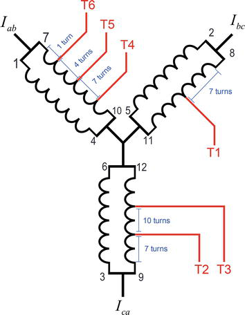
A common fault in three-phase induction motors is the incipient short-circuit condition on the stator windings. In this work, this defect is produced artificially on the stator winding corresponding to the line current Iab of a 3-Hp, 220 V, high-efficiency induction motor from Siemens, by modifying its windings to induce the short-circuit fault. This alteration is performed by rewinding the induction motor and bringing out several taps for generating different short-circuit stator fault scenarios, as portrayed in Figure 1.
Figure 1.
Stator winding alteration taps.
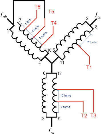
The faulty condition in the induction motor is created by connecting terminal 7 with tap 5, suppressing 5 out of 45 coils in the corresponding winding, as depicted in the schematic diagram shown in Figure 2.
Figure 2.
Stator winding modification to produce a 5-turn short-circuit fault scenario.
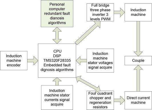
Different techniques for induction motor fault diagnosis are assessed by performing 30 trials in healthy condition and 30 experiments in faulty condition, each one containing 128 discrete samples. The signal processing analysis is performed by a digital system based on the 32-bit, floating-point digital signal processor (DSP) TMS320F28335 from Texas Instruments, which is integrated in the sequential diagram displayed in Figure 3.
Figure 3.
Digital signal processing flowchart.
Figure 4 shows the experimentally acquired stator currents utilizing a sampling frequency Fs=3,840 Hz. This sampling frequency is chosen to be a multiple of the induction machine nominal operation frequency 60 Hz, which produces a rotational speed of 1800 rpm.
Figure 4.
Stator line currents for the healthy case.
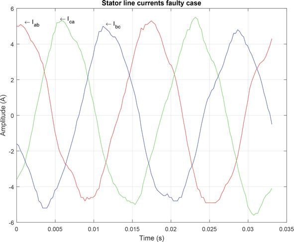
The faulty scenario described above is created by reducing the number of coils in the phase-A winding of the induction motor. The coils 41 to 45 (i.e., five coils) are short circuited. The resulting stator currents are acquired experimentally and shown in Figure 5.
where ia,ib,ic are the currents in phase a, phase b, phase c, and the neutral, respectively, with positive, negative, and zero sequence components. The instantaneous-space phasor currents for phase a, phase b, and phase c are defined as:
The phasor squared magnitude is a meaningful quantity related to the instantaneous space phasor (ISP) that helps on separating the positive and negative sequence components as follows:
I˜2=I˜++I˜−2=I˜+2+I˜−2+2I˜+I˜−cos2wt+φ++φ−E3
The average squared ISP value is computed by:
I˜2=I˜+2+I˜−2E4
From (4), I˜2 has the distinctive feature of oscillating between a maximum value:
I˜M2=I˜++I˜−2E5
and a minimum value:
I˜m2=I˜+−I˜−2E6
Solving Eqs. (5) and (6), the positive and negative sequence components are, respectively:
Î+=I˜M+I˜m/2Î−=I˜M−I˜m/2E7
Hence, the ISP limit values can be used for obtaining the positive and negative sequence components. The same precept can be applied to the voltage signals. Therefore, I˜+;I˜−;V˜+ y V˜− monitoring allows estimating the current and voltage unbalance; for instance, the current unbalance can be computed by:
%IU=100Î−Î+=100I˜M−I˜mI˜M+I˜mE8
From the aforesaid, the ISP can be used for detecting and classifying electric faults in the induction-motor stator. The ISP or instantaneous space phasor is a widely used tool for analyzing three-phase systems, which allows determining the current signal unbalance in these systems by associating a three-phase reference framework into a two-phase scheme. There are two possible transformations to carry out this conversion: the variable framework scheme known as d-q transform, described in Eq. (9), and the fixed framework equivalence named Concordia or α−β transform, defined in Eq. (10). In this work, the Concordia transform is used; therefore, the stator currents are mapped into the two-phase stationary α−β reference frame.
where ia,ib,ic are the instantaneous current values from the induction motor stator, and the instantaneous values from the Park vectors in the variable reference framework d-q are id,iq and i0. For the stationary reference frame α−β, or Concordia transform, the current instantaneous values are iα,iβ and i0.
The modulus of the instantaneous space phasor is obtained by:
iαβ2=iα2+iβ2E11
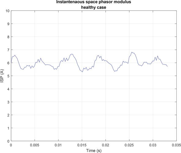
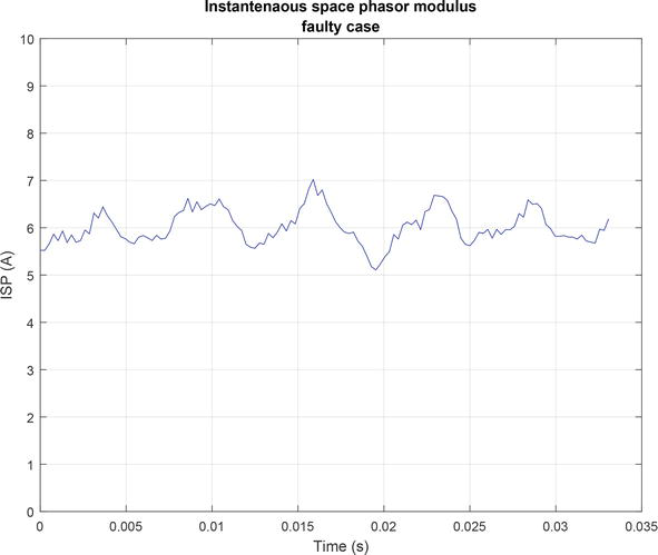
Figure 6 depicts the experimentally obtained modulus of the Park phasor or ISP from the stator currents of a healthy motor utilizing the fixed framework or Concordia transform. Figure 7 shows the ISP modulus of an incipient fault, where five coils of the phase a winding in the induction motor stator are short circuited.
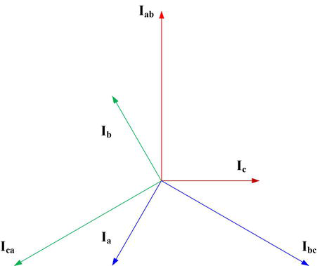
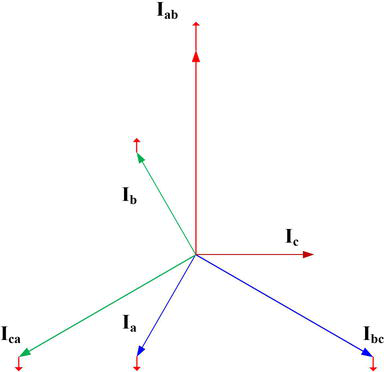
For analyzing short-circuit faults in the stator, the phasor relations in Eq. (13) and in Eq. (12) between line and phase currents of the induction-motor stator are considered in normal operation, utilizing the per-unit system, as it is illustrated in Figure 8.
Figure 8.
Healthy current phasors of the line currents and phase currents.
Phasor representation of line currents:
Iab=3∠90°Ibc=3∠−30°Ica=3∠−150°E12
Phasor representation of phase currents:
Ic=1∠0°Ia=1∠−120°Ib=1∠120°E13
For any balanced three-phase system connected to an induction motor, the supplied currents to the stator must comply with the following requirements because of the absence of a neutral connection:
Ia+Ib+Ic=0E14
Considering the stated before, the phasor components of each stator current are obtained utilizing both framework systems. It can be observed from Figure 8, Eq. (13), and Eq. (12) that a specific phase current is always perpendicular to a particular line current as follows:
Ibc⊥IaIca⊥IbIab⊥IcE15
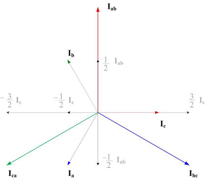
Figure 9 shows how each current phasor can be represented by components on the direction of corresponding components over the reference frame created by Ic and Iab to obtain the expressions in Eq. (16).
Current phasor components on the direction of Iab⊥Ic.
Following the same precept, it is possible to obtain equivalent expressions to those in Eq. (16) for the reference systems Ica⊥Ib and Ibc⊥Ia.
4.1 Phasorial short-circuit fault detection and isolation
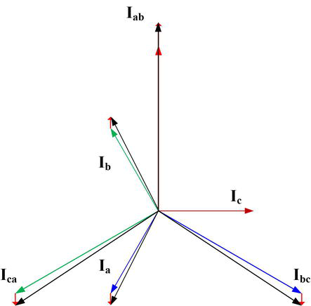
A diagnosis system can be assumed from the corresponding phasor representations of phase and line currents to detect magnitude and angle variations over the current signals when a short-circuit fault takes place on the stator windings of an induction motor. Figure 10 shows the trajectory variations on the phase and line current phasors when a short-circuit fault occurs on Iab.
Figure 10.
Directions of current phasor variations in the event of a short-circuit fault in Iab.
If the phasor of line current Iab increases because there is a short-circuit fault on some coils of the corresponding stator windings, then, the remainder phasor currents shift along parallel lines to the faulty line current. The variations on magnitude and direction of the current phasors are computed through Eq. (16). For instance, if a short-circuit fault takes place on the stator winding corresponding to the line current Iab, the reminder line currents shift along parallel lines in opposite direction to Iab, as depicted in Figure 10, where the faulty line current Iab is represented in a vertical direction upwards; therefore, the line currents Ica and Ibc shift vertically downward. On the other hand, it is worth it to notice that the magnitude and angle of the phase current Ic do not change, whereas the magnitude and angle of phase currents Ia and Ib do change. This behavior from line and phase current phasors, when a short-circuit fault occurs, emerges from choosing the Iab⊥Ic reference framework, which involves the phasor of the faulty line current Iab. Therefore, to diagnose a short-circuit fault it is necessary to take into account the phase and line current behavior. The detection and classification of the faulty condition can be achieved by observing the phase current that remains unchanging. In Figure 11, the magnitude and angle variations on the current signals are represented through the phasors in black color, when a faulty condition occurs on the line current Iab. It can be observed that just the phase current Ic remains constant, which signifies that the line current Iab increases because there is a faulty condition.
Figure 11.
Displacement of current phasors during a short-circuit fault in Iab.
4.2 Frequency analysis
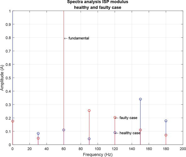
The diagnosis of stator electric faults in an induction motor can be accomplished through the motor current signature analysis (MCSA), which is performed by examining in the frequency domain the ISP modulus defined in Eq. (11), taking into consideration the following spectral description [8]. Since the negative-sequence components of the current are directly related to the motor asymmetry, the presence of a faulty condition on the stator can certainly be indicated by a spectral analysis of the ISP [9]. For the stator electric fault, its frequency signature Fstator in the ISP spectrum takes place on integer multiples nn=1,2,3…∞ of twice the power-line frequency fL.
Fstator=2nfLE17
The magnitude of the characteristic fault frequency decreases as the multiple n increases; therefore, the characteristic fault frequency for n = 1 is used in practice because it possesses the highest magnitude; hence:
Fstator=2fLE18
Figure 12 shows the spectra comparison between the healthy and faulty conditions, carried out experimentally, when five coils are short circuited in one stator winding of the induction motor.
Figure 12.
Comparative analysis of ISP spectra from the healthy and faulty cases.
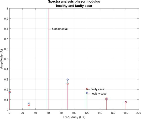
Another tool, proposed in Ref. [10], for diagnosing electric faults consists in assessing the phasor representation of the line and phase currents. Figure 13 shows the phasor frequency spectrum for the healthy and faulty conditions, which allows the diagnosis and classification of the faulty state, different from the ISP modulus that just identifies the fault presence.
Figure 13.
Comparative analysis of phasor spectra from the healthy and faulty cases.
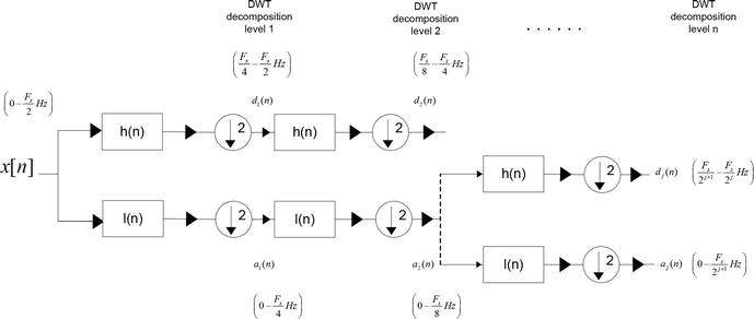
The discrete wavelet transform (DWT) is a mathematical tool, with an effective structure, which allows breaking up a fault signature in the ISP modulus into distinct scales with different levels of resolution [11]. The DWT can be used as back-up tool, besides the frequency spectrum of the ISP modulus and the current phasor analyses, to perform a multiresolution analysis (MRA) for determining the root-mean-square (RMS) (i.e., effective) value of the wavelet coefficients on each frequency band. Figure 14 portrays graphically the multilevel decomposition.
Figure 14.
Scheme for wavelet multiresolution analysis.
5.1 Haar mother wavelet function
The simplest mother wavelet function is the Haar function. In its discrete form, it relates to the Haar transformation, which decomposes one signal into two constituent elements, the approximation am and detail dm, with the same length.
The approximation coefficients for m=1,2,3,…,N/2, where N is the original signal length, are computed by:
am=f2m−1+f2m2E19
The detail coefficients for m=1,2,3,…,N/2 are computed by:
dm=f2m−1−f2m2E20
The level-1 Haar transform is computed through:
f→H1a1d1E21
Its corresponding inverse transformation is calculated by:
f=a1+d12a2−d22…aN/2+dN/22aN/2−dN/22E22
The second transformation level is obtained by decomposing the level-1 approximation coefficients a1 to produce the level-2 approximation a2 and detail d2 coefficients.
f→H2a2d2d1E23
The Haar mother wavelet is used for obtaining multiple approximation levels to perform the MRA as follows:
The short-circuit fault in the induction-motor stator is inspected exhaustively through the MRA of the ISP utilizing the Haar mother wavelet. Table 1 shows a comparative analysis of RMS values for the wavelet coefficients on each frequency bad. The induction motor has an 1800 rpm rotational speed, with a 60-Hz fundamental frequency from the power supply. Since the induction motor has two poles, the fault characteristic frequency appears at twice its fundamental frequency ffault=120 Hz; hence, the RMS value increases from 0.989168 for the healthy case to 10.020093 for the faulty state. On the other hand, it is worth to notice that there is a significant difference between the wavelet-coefficients RMS values for a healthy and a faulty motor in the 30–60 Hz frequency band, which are 0.597124 and 50.795688, respectively, because of the fundamental-frequency variation in the induction motor.
Level
Frequency band (Hz)
Healthy (RMS)
Faulty (RMS)
1
960.0–1920.0
0.119505
0.492522
2
480.0–960.0
0.223134
1.378206
3
240.0–480.0
0.461718
3.789614
4
120.0–240.0
0.989168
10.020093
5
60.0–120.0
0.533128
2.238111
6
30.0–60.0
0.597124
50.795688
7
15.0–30.0
0.619910
0.220971
Table 1.
RMS values from the MRA on the ISV utilizing the level-1, Haar-wavelet coefficients.
The phasor analysis, which can detect and classify the faulty condition, is applied through a MRA for diagnosing short-circuit faults in the induction-motor stator, too. In Table 2, a significative change in the RMS value of the 120–240 Hz frequency band is observed, from 0.852141 for the healthy condition to 10.429046 for the faulty state. On the other hand, it is worth to notice the variation between the RMS values of the wavelet coefficients in the 30–60 Hz frequency band, from 0.597124 to 50.795688, for a healthy and a faulty condition, respectively, due to the fundamental-frequency variation in the induction motor.
Level
Frequency band (Hz)
Healthy (RMS)
Faulty (RMS)
1
960.0–1920.0
0.113843
0.532535
2
480.0–960.0
0.243338
1.395585
3
240.0–480.0
0.501377
3.839840
4
120.0–240.0
0.852141
10.429046
5
60.0–120.0
0.731468
3.617190
6
30.0–60.0
0.984967
48.763207
7
15.0–30.0
0.492005
0.159099
Table 2.
RMS values from the MRA on the phasors utilizing the level-1, Haar-wavelet coefficients.
6. Fault diagnosis and classification through fuzzy logic
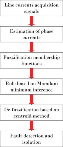
Fuzzy logic offers the advantage of recognizing phase and line-current asymmetries. Since the line currents are obtained straight forward from the induction-motor stator, the phase currents must be estimated to compute the RMS values that are used as input to the fuzzy-logic system, which is based on the Mamdani model, to detect and classify the short-circuit fault, as shown in Figure 15.
Figure 15.
Fuzzy logic algorithm based on Mamdani model.
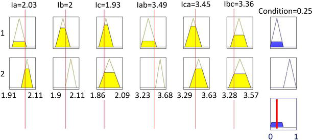
In Table 3, the line-current RMS values do not show significant changes among them, neither the phase currents do. Figure 16 shows the obtained results from introducing the RMS values to the fuzzy-logic system, which detects the induction motor condition as healthy by providing an outcome of 0.25 that is computed through the centroid method. The discourse universe in the fuzzy system takes the values from 0 to 1 for identifying the induction motor condition. For the healthy condition, the membership zone goes from 0 to 0.5, whereas the faulty condition region goes from 0.5 to 1.
Trial
Ia
Ib
Ic
Iab
Ica
Ibc
1
2.02
1.99
1.93
3.49
3.45
3.36
2
1.98
1.97
1.94
3.41
3.51
3.37
3
2.02
1.98
1.97
3.52
3.52
3.41
4
1.95
1.97
1.93
3.35
3.39
3.41
5
1.93
1.92
1.96
3.25
3.42
3.47
Table 3.
RMS values of line and phase currents in healthy condition.
Ia,Ib,Ic are phase currents estimated from the stator line currents.
Iab,Ica,Ibc are stator line currents.
Figure 16.
Detection of the healthy operational condition of the induction-motor stator through fuzzy logic.
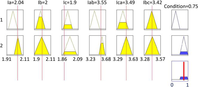
Connecting the Tap 5 as described in Figure 2 generates a short-circuit fault on 5 out of 45 coils in the corresponding winding; therefore, the line current Iab increases provoking the escalation of phase currents Ia and Ib; however, Ic remains unaffected as described in Table 4. In this way, the fuzzy system is able to detect and classify the faulty condition by producing an outcome of 0.75, which points out that there is a short-circuit fault as depicted in Figure 17.
Trial
Ia
Ib
Ic
Iab
Ica
Ibc
1
2.04
2.01
1.98
3.55
3.49
3.42
2
2.09
2.03
1.99
3.62
3.47
3.43
3
2.07
2.02
1.88
3.58
3.38
3.29
4
1.99
2.02
1.99
3.51
3.49
3.49
5
2.02
2.06
1.99
3.57
3.50
3.46
Table 4.
RMS values of line and phase currents in faulty condition.
Ia,Ib,Ic are phase currents estimated from the stator line currents.
Iab,Ica,Ibc are stator line currents.
Figure 17.
Detection and classification of the short-circuit fault on the induction-motor stator utilizing fuzzy logic.
This work presents several techniques for detecting short-circuit faults in three-phase induction motors. Among these approaches are spectral-frequency tools as discrete Fourier transform and discrete wavelet transform, which employ the instantaneous space phasor (ISP) modulus without achieving the fault classification. Hence, a novel technique relaying on the phasor analysis of the three-phase currents is put forward, which in addition to detect the faulty condition, it is capable of classifying through a fuzzy system with a Mamdani model by examining the current RMS values as input data.
This work was partially supported by DEPI-ITA-TecNm (Departamento de Posgrado e Investigacion—Instituto Tecnologico de Aguascalientes/Tecnologico Nacional de Mexico), Departamento de Produccion y Seguridad Industrial, Universidad Tecnologica de Aguascalientes, Aguascalientes, Multidisciplinary Studies Department, Engineering Division, Campus Irapuato-Salamanca, University of Guanajuato.
The Institute of Electrical and Electronics Engineers
EPRI
Electric Power Research Institute
ITSC
Inter Turn Short Circuit
SVM
Support Vector Machine
IM
Induction Machine
ISP
Instantaneous Space Phasor
MRA
Multiresolution Analysis
DSP
Digital Signal Processor
Nomenclature
T1
Stator motor winding artificial fault tap 1
T2
Stator motor winding artificial fault tap 2
T3
Stator motor winding artificial fault tap 3
T4
Stator motor winding artificial fault tap 4
T5
Stator motor winding artificial fault tap 5
T6
Stator motor winding artificial fault tap 6
T7
Stator motor winding artificial fault tap 7
Ia
Phase A current
Ib
Phase B current
Ic
Phase C current
Iab
Phase A to B line current
Ibc
Phase B to C line current
Ica
Phase C to A line current
Fstator
Stator Fault
fL
Line frequency
Id
d current in the dq reference frame
Iq
q current in the dq reference frame
Iα
α current in the α‐β reference frame
Iβ
β current in the α‐β reference frame
I0
0 current in the dq reference frame and α‐β reference frame
References
1.Garcia-Calva T, Morinigo-Sotelo D, Fernandez-Cavero V, Romero-Troncoso R. Early detection of fault in induction motors - a review. MDPI Energies. 2022;15(1):1713-1721. DOI: 10.3390/en15217855
2.Jigyasu R, Mathew L, Sharma A, Chatterji S. A review of condition monitoring and fault diagnosis methods for induction motor. In: Second International Conference on Intelligent Computing and Control Systems (ICICCS 2018). IEEE Xplore; 2018. pp. 1713-1721. DOI: 10.1109/ICCONS.2018.8662833. ISBN:978-1-5386-2841-6
3.Bazan G, Scalassara P, Endo W, Goedtel A, Palácios R, Godoy W. Stator short-circuit diagnosis in induction motors using mutual information and intelligent systems. 2019;66(4):3237-3246. DOI: 10.1109/TIE.2018.2840983
4.Bensaoucha S, Brik Y, Moreau S, Bessedik S, Ameur A. Induction machine stator short-circuit fault detection using support vector machine. The International Journal for Computation and Mathematics in Electrical and Electronic Engineering. 2021;40(3):373-389. DOI: 10.1108/COMPEL-06-2020-0208
5.Rajamany G, Srinivasan S, Rajamny K, Natarajan RK. Induction motor stator inter turn short circuit fault detection in accordance with line current sequence components using artificial neural network. Journal of Electrical and Computer Engineering. Hindawi. 2019;2019:1-11. DOI: 10.1155/2019/4825787
6.Nandi S, Toliyat HA, Li X. Condition monitoring and fault diagnosis of electrical motors a review. IEEE Transactions on Energy Conversion. 2007;20(4):719-729
7.Milanez DL, Emanuel AE. The instantaneous-space-phasor a powerful diagnosis tool. IEEE Transactions on Instrumentation and Measurement. 2003;51(1):143-148
8.Cruz S, Cardoso AJM. Multiple reference frames theory: A new method for the diagnosis of stator faults in three-phase induction motors. IEEE Transactions on Energy Conversion. 2005;20(1):289-299
9.Cruz SMA, Cardoso AJM. Stator winding fault diagnosis in three-phase synchronous and asynchronous motors, by the extended Park’s vector approach. IEEE Transcations on Industry Applications. 2001;37(5):1227-1233
10.Reyes-Malanche JA, Villalobos-Pina FJ, Ramırez-Velasco E, Cabal-Yepez E, Hernandez-Gomez G, Lopez-RamirezCruz M. Short-circuit fault diagnosis on induction motors through electric current phasor analysis and fuzzy logic. MDPI Energies. 2023;16(516):1-15. DOI: 10.3390/en16010516 [Accessed: January 03, 2023]
11.Walker JS. A Primer on Wavelets and their Scientific Applications. 2nd ed. Chapman & Hall/CRC Taylor and Francis Group; 2008
Written By
Francisco Javier Villalobos-Pina, Josue Augusto Reyes-Malanche, Eduardo Cabal-Yepez and Efrain Ramirez-Velasco
Submitted: 13 September 2023Reviewed: 29 November 2023Published: 05 January 2024