Open Access is an initiative that aims to make scientific research freely available to all. To date our community has made over 100 million downloads. It’s based on principles of collaboration, unobstructed discovery, and, most importantly, scientific progression. As PhD students, we found it difficult to access the research we needed, so we decided to create a new Open Access publisher that levels the playing field for scientists across the world. How? By making research easy to access, and puts the academic needs of the researchers before the business interests of publishers.
We are a community of more than 103,000 authors and editors from 3,291 institutions spanning 160 countries, including Nobel Prize winners and some of the world’s most-cited researchers. Publishing on IntechOpen allows authors to earn citations and find new collaborators, meaning more people see your work not only from your own field of study, but from other related fields too.
Metal foam as flow field for proton exchange membrane fuel cell (PEMFC) has demonstrated substantial promise for enhancing the distribution uniformities of reactants and temperature. In different types of PEMFC, however, the influence of metal foam flow field on cell performance is diverse. For liquid-cooled PEMFC, employing metal foam flow field encounters challenges in water removal. For air-cooled PEMFC, employing metal foam can help retain a certain amount of liquid water to avoid membrane dehydration. In an effort to further enhance the cell performance and practical application potential of metal foam in different types of PEMFC, the design strategy for metal foam flow field in PEMFCs is studied through this chapter. Experimental results revealed that for liquid-cooled PEMFC, the cathode side employing metal foam flow field raises the potential for water flooding and instability of operational voltage, which can be addressed through reasonably designing the structural characteristics of metal foam. Furthermore, the thermal management capability of air-cooled PEMFC can be boosted through adopting metal foam flow field, owing to the synergic improvement of forced convective heat transfer of reactant gas and electrochemical performance, which is the main factor of the thermal management improvement at high current.
College of Mechanical Engineering, Hunan Institute of Science and Technology, Yueyang, China
Yun Sun
Fujian Universities Engineering Research Center of Reactive Distillation Technology, College of Chemical Engineering, Fuzhou University, Fuzhou, Fujian, China
Chen Yang*
Fujian Universities Engineering Research Center of Reactive Distillation Technology, College of Chemical Engineering, Fuzhou University, Fuzhou, Fujian, China
*Address all correspondence to: cyang@fzu.edu.cn
1. Introduction
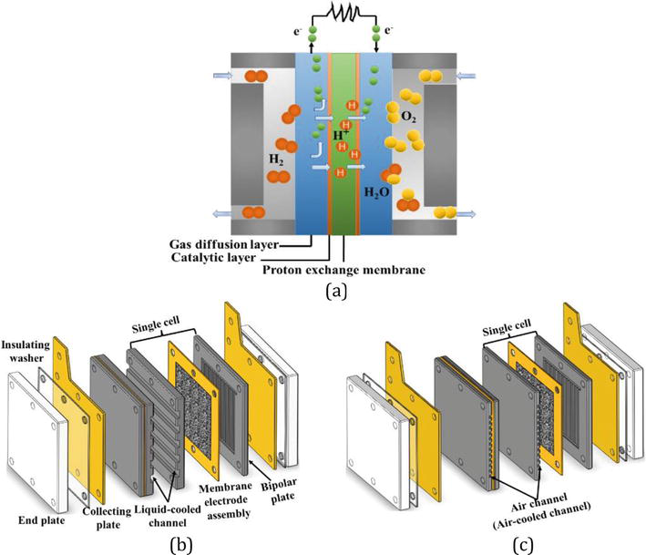
Due to the global desire for more efficient and environmentally friendly energy usage, proton exchange membrane fuel cell (PEMFC), which is being recognized as a potential substitute for internal combustion engines, has gained increasing interest of scholars owing to its remarkable attributes such as excellent efficiency, low operating temperature, quickly starting speed, and environmentally clean operation [1]. The electrochemical mechanism and components of different types of PEMFC are depicted in Figure 1. In the past few years, PEMFC has experienced significant advancements and has found diverse applications in areas such as spacecraft, emergency supply, and transportation [2]. Enhancing the performance of PEMFC is crucial to expand its application areas.
Figure 1.
The electrochemical mechanism and components of different types of PEMFC. (a) Schematics of the electrochemical mechanism of PEMFC. (b) Liquid-cooled PEMFC. (c) Air-cooled PEMFC.
Bipolar plate (BP), an essential constituent of PEMFC, plays a pivotal role in providing structural support and anchoring the membrane electrode assembly (MEA). Apart from these functions, flow field in BP performs additional vital functions, like distributing the reactants and products, collecting current and discharging, and so forth. The flow field design and optimization in BP play a crucial role in determining the performance of PEMFCs. Consequently, numerous scholars [3, 4, 5] have dedicated their efforts to designing and optimizing flow field for boosting the output performance of PEMFCs. Yan et al. [6] presented an innovative 3D serpentine flow channel that equips with a gradient wave structure. According to numerical and experimental results, in comparison with traditional serpentine flow channel, this innovative 3D serpentine flow channel exhibits the potential for enhancing the diffusion of the reactants to the catalytic layer (CL). Moreover, this innovative flow channel has the capability to augment the flow velocity, thus effectively removing excess liquid water. However, conventional flow field design in BPs frequently results in inhomogeneous gas distribution on the MEA particularly beneath the ribs. This, in result, leads to inhomogeneous electrochemical reaction and localized areas of elevated temperature at the MEA. The phenomenon of localized areas of elevated temperature is detrimental to the durability of the MEA. In recent times, there has been considerable interest in utilizing metal foam as flow distributor for PEMFC owing to its exceptional distribution properties.
Metal foam exhibits remarkable electrical and thermal conductive properties, in addition to possessing high porosity as well as a substantial specific surface area [7, 8]. The reactant distribution uniformity, thermal management, and performance of PEMFC can be effectively boosted by the adoption of metal foam flow field. The study conducted by Afshari et al. [9] involved a numerical comparison of the performances of PEMFCs equipped with a partially restricted flow field as well as metal foam flow field. The findings demonstrated that the distribution uniformities of current density and oxygen concentration at the CL can be boosted by the implementation of metal foam flow field. In addition, based on the experimental results of Awin and Dukhan [10], it was depicted that by comparing with serpentine flow field, metal foam design can offer more homogeneous distributions of temperature on the MEA. Nevertheless, for liquid-cooled PEMFC, the utilization of metal foam flow field causes water discharge issue affecting the operation stability. Tseng et al. [11] identified that some pores in metal foam were clogged by liquid water, causing the water flooding phenomenon. In contrast, in the case of air-cooled PEMFC, the adoption of a metal foam flow field demonstrates the capability to retain water leading to a better equilibrium between heat dispersion and water preservation. Kang et al. [12] carried out numerical and experimental researches to examine the influence of metal foam on the water management as well as output performance of air-cooled PEMFC. The findings obtained from their research revealed that the implementation of metal foam in the cathode side effectively inhibits the membrane dehydration phenomenon. In view of this, the design strategy for metal foam flow field in various types of PEMFC is crucial for improving the cell performance and enhancing the potential for practical implementation of metal foam flow field. However, the study related to the metal foam design strategy for PEMFC is rare in the open literature.
In this chapter, the design strategy for metal foam flow field in liquid-cooled PEMFC and air-cooled PEMFC is extensively investigated through three sections. The influence of the arrangement of metal foam flow field on the cell performance as well as water management is thoroughly explored. A 3-hour constant current density operational test is conducted for assessing the operation stability associated with the water flooding phenomenon. Structural characteristics of metal foam flow field are also developed for addressing the water flooding issue. Furthermore, the influence of metal foam flow field on the thermal management and performance of air-cooled PEMFC is studied.
2.1 Design of metal foam flow field and assembled of single cell
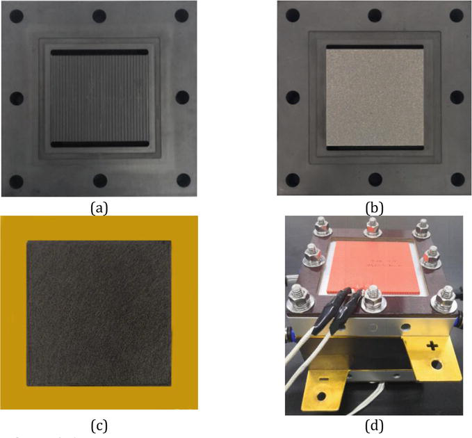
The metal foam with various structures applied in this chapter was nickel-based (Guangjiayuan Electronic Materials Co., Ltd., Kunshan City). Since the active area of PEMFC is 50 mm × 50 mm, it is necessary to cut the sample by a laser with a precision of ±0.1 mm to guarantee that the pores located in the cutting region remain unclogged. Additionally, the experimental MEA adopted for this chapter was produced by Wuhan University of Technology. In Figure 2, the BP with different flow fields, MEA, and single cell used for experiments are depicted.
Figure 2.
Straight flow field, metal foam flow field, MEA, and single cell.
2.2 Test system
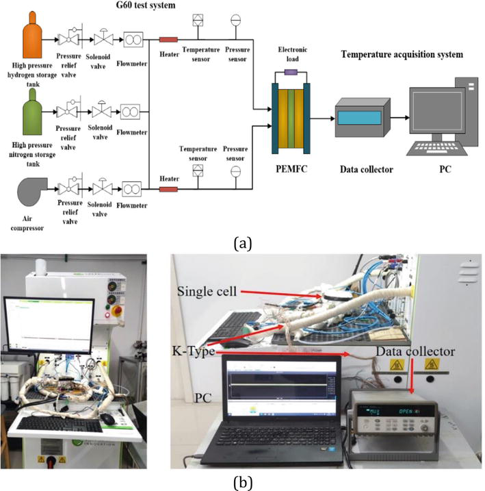
The experimental setup for testing PEMFC, referred to as the G60 fuel cell test system, is depicted in Figure 3. This system comprises various components like a gas storage device, heating device, pipeline network, moisture control device, thermal insulation device, monitoring and control device, PEMFC, reactants mass flow control device, and so on.
Figure 3.
Diagrammatic representation and picture of the entire experimental system.
3. Performance and water management investigation on the arrangement of metal foam flow field in liquid-cooled PEMFC
In this section, four cases are established as depicted in Table 1 to evaluate the influence of the arrangement of metal foam flow field on the performance of PEMFC. The difference in the water management of different cases is also examined. Note that the porosity, thickness, and pore diameter of metal foam employed in this section are 95–97%, 1, and 0.2 mm, respectively. The experimental operation conditions are also depicted in Table 2.
Case No.
Explanations
Case 1
Straight flow field for anode and cathode
Case 2
Metal foam flow field for anode and straight flow field for cathode
Case 3
Straight flow field for anode and metal foam flow field for cathode
Case 4
Metal foam flow field for anode and cathode
Table 1.
Explanation of different cases.
Operation condition
Value
Operation temperature
70°C
Relative humidity of H2
0/0.5/0.8/1
Relative humidity of air
0/0.5/0.8/1
Stoichiometric flow ratio of H2
1.2
Stoichiometric flow ratio of air
2.5
Operating pressure
1 atm
Table 2.
Operation conditions for experiments in this section.
3.1 Influence of relative humidity
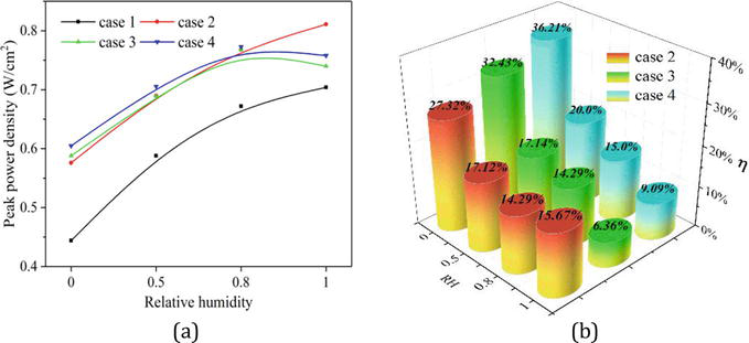
The influence of relative humidity (RH) of reactants on the cell performance was studied in this subsection; Figure 4 shows the peak power density of four cases and the peak power density augmentation rate (η) for cases 2–4 in comparison with that for case 1 under various RHs.
Figure 4.
(a) Peak power density of four cases under various RHs; (b) peak power density augmentation rate of cases 2–4 in comparison with that of case 1.
According to Figure 4, adopting metal foam flow field can result in the improved cell performance over traditional straight flow field, which conforms to the findings from Jo and Ju [13]. Additionally, when RH is set to 1, the augmentation rates of peak power density in cases 3 and 4, both utilizing metal foam flow field in the cathode side, are 6.36 and 9.09%, respectively. In case 2, the augmentation rate η is more noticeable, reaching 15.67% when only utilizing metal foam flow field in the anode side. The reason is that liquid water is produced in the cathode catalytic layer during the operation of PEMFC. Furthermore, the migration of protons through the membrane also results in the accumulation of liquid water in the cathode side. Therefore, when setting a high RH, a significant quantity of liquid water can fill the reactants passage in the gas diffusion layer (GDL) in the cathode side, resulting in water flooding and detrimental effects on the performance of PEMFC.
3.2 Flooding test and analysis
According to the study conducted by Bao et al. [14], it was asserted that removing liquid water poses a greater challenge for metal foam flow field in comparison with traditional straight flow field, primarily owing to the complex internal structure impeding effective water removal. When RH and current are high, the implementation of metal foam in the cathode side results in the water flooding phenomenon, affecting the cell performance. In contrast, the implementation of metal foam flow field demonstrates water retention capability when RH is low, wetting the membrane, thereby enhancing the rate of mass transfer in the membrane and improving the cell performance in comparison with traditional straight flow field.
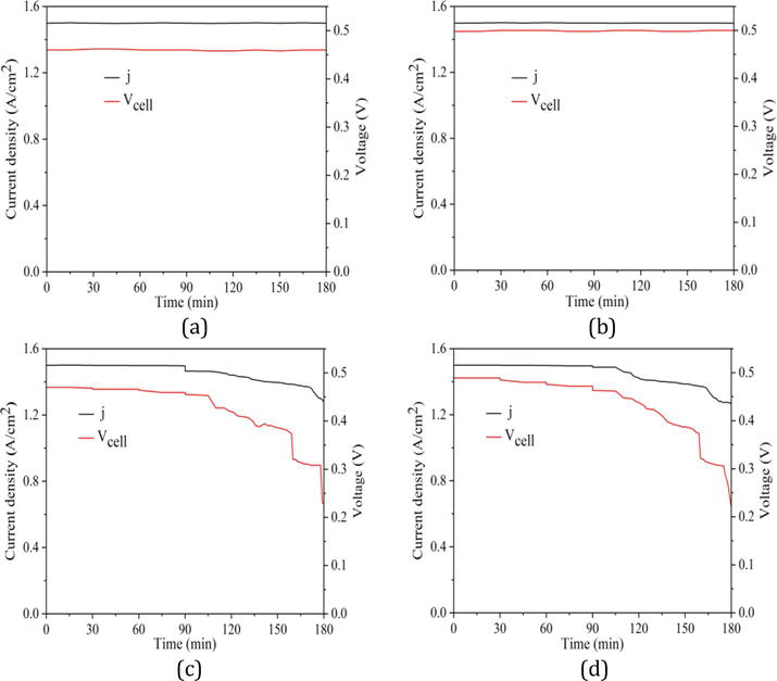
Considering the test processes mentioned above, PEMFC adopting metal foam as cathode flow field easily results in the occurrence of the water flooding phenomenon at high current and RH. In order to gain deeper insights into the flooding phenomenon, 3-hour constant current density operational test on four cases under different RHs was performed in this subsection. The current density is fixed at 1.5 A/cm2. Figure 5 presents the variations of voltage and current density over time in different cases under RH = 1. It is evident that over the 3 hours of operation, the voltages and current densities of cases 1 and 2 essentially remain steady. However, there were four minor voltage attenuations during the initial 105 minutes in cases 3 and 4. Following that, the voltage started to attenuate quickly. The underlying cause for this can be attributed to the implementation of metal foam as flow field in the cathode side in these two cases. In the course of PEMFC operation, liquid water slowly accrues and cannot be effectively removed in time, resulting in the reactants channel in the GDL to be filled. The voltage gradually decreased, while PEMFC operates in a constant current density model.
Figure 5.
Voltage and current density over time of different cases under RH of 1. (a) Case 1. (b) Case 2. (c) Case 3. (d) Case 4.
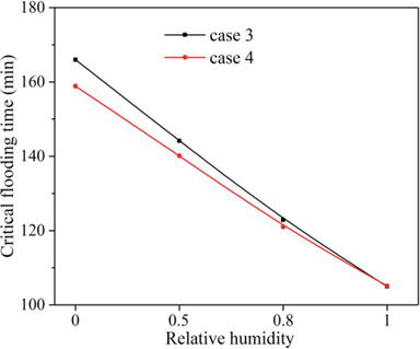
In Figure 6, the correlations between RH and crucial flooding time of cases 3 and 4 are depicted. It is evident that as RH decreases, the crucial flooding times for these two cases experience a gradual delay. Thus, it can draw the conclusion that arranging metal foam flow field in the cathode side leads to the water flooding issue, negatively impacting the cell performance.
Figure 6.
Correlations between the RH and crucial time of flooding in cases 3 and 4.
4. Investigation of water management and structure optimization of metal foam flow field in liquid-cooled PEMFC
As stated before, the water flooding phenomenon occurs under the high current density and high RH, when metal foam was adopted in the cathode side of PEMFC. In addition, Bao et al. [15] pointed out that the reactant velocity affected by structural parameters of flow field has a significant influence on the water discharging in PEMFC. Therefore, the influences of the structural characteristics of metal foam like compression rate and pore per inch (PPI) on the water management as well as cell performance are investigated in this section. It should be noted that the cathode flow field depth is 0.5 mm. Traditional straight flow field is set with channel dimensions of 1 mm for width, height, and rib width in the anode side. RHs for both anode and cathode are all 1.
4.1 Influence of compression rate
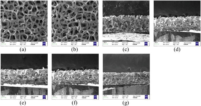
For the purpose of examining the influence of the metal foam compression rate on the water management and cell performance, metal foam flow fields with various compression rates are set up in the cathode side of PEMFC in this subsection. Figure 7 displays SEM images of metal foam including various compression rates. Obviously, the pore diameter of metal foam in the direction perpendicular to the reactants flow reduces, while it basically remains unchanged in the flow direction of reactants as the increase of the compression rate. Hence, the reactant diffusion to the GDL can be enhanced through the compression of metal foam. However, compressing metal foam will also lead to a reduction in porosity. Based on the results of Shin et al. [16] and Tseng et al. [11], metal foam has a larger porosity, which indicates that there is more space for reactants improving the homogeneity of the reactant distribution. Thus, compressing metal foam does not favor achieving homogeneous reactant distribution.
Figure 7.
SEM images: (a, b) overhead perspective of metal foam exhibiting compression rates of 0 and 0.75; (c, g) cross-sectional depiction of metal foams showcasing diverse compression rates, specifically 0, 0.38, 0.50, 0.69, and 0.75.
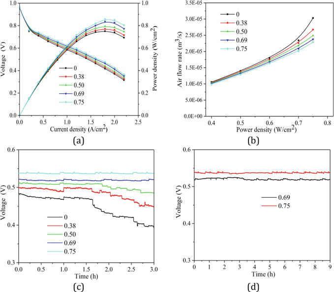
From Figure 8(a), when the compression rate of metal foam flow field in the cathode side rises, it is clear that the cell performance is enhanced. As shown in Figure 8(b), the cell performance enhancement also improves the air utilization. The reason is that reactant diffusion to the CL is boosted by the increment in the compression rate of metal foam flow field. This notion is also supported by the findings of Park et al. [17]. More crucially, as demonstrated in Figure 8(c), the increment in the compression rate also leads to better voltage stability of PEMFC, suggesting that the water management capability is enhanced. It is worth noting that the operation voltage is totally stable as soon as the metal foam compression rate rises over 0.69. In order to analyze this point more clearly, the duration of constant current density operational tests for PEMFCs utilizing the compression rates of 0.69 and 0.75 was extended to 9 hours as depicted in Figure 8(d). Based on the results presented in Figure 8(c, d), the utilization of metal foam with a compression rate higher than 0.69 can significantly improve the water management in PEMFCs.
Figure 8.
(a) Polarization curves; (b) comparison of air flow rate; (c, d) voltage over time.
4.2 Influence of PPI
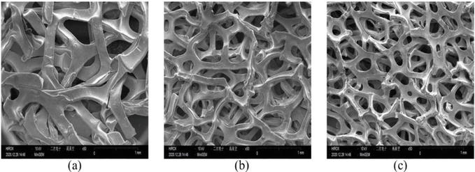
In this subsection, the cathode of PEMFC is equipped with metal foam flow fields featuring various PPIs. From Figure 9, the pore density rises as the increment of PPI of metal foam, which is helpful for the reactants to be distributed uniformly. However, the increase of PPI will also lead to a reduction in pore diameter and permeability of metal foam. Liquid water first percolates into metal foam flow field via the GDL and subsequently exits through flow field outlet. The removal of liquid water through the GDL to cathode flow field is hindered by the reduction in permeability. As a result, the synergistic influence of PPI on homogeneity of reactants distribution and water management is examined in this subsection.
Figure 9.
SEM images: Overhead perspective of metal foams with various PPIs: (a) 35 PPI, (b) 75 PPI, (c) 110 PPI.
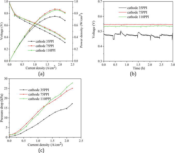
The polarization curves of PEMFCs comprising various PPIs in the cathode side are depicted in Figure 10(a). It is interesting to observe that the performance of PEMFC adopting metal foam flow field with 75 PPI is the best. This outcome can be attributed to the synergistic influence between reactant distribution and water management. In Figure 10(b, c), the pressure drop from cathode inlet to outlet and operation voltage stability of PEMFCs are provided. As seen in Figure 10(c), under current density of 2.2 A/cm2, the pressure drops from cathode inlet to outlet of PEMFCs with 35 PPI, 75 PPI, and 110 PPI are 17.2, 25.1, and 27.8 kPa, respectively. It is also worth noting that prior to 1.25 A/cm2, the pressure drop of metal foam with 110 PPI is practically indistinguishable from that with 75 PPI. Revealing that the disparity in the pressure drops attributable to pore diameter between 75 PPI and 110 PPI can be disregarded in the presence of a small amount liquid water. However, the pressure drop of 110 PPI is obviously larger than that of 75 PPI, after 1.25 A/cm2, owing to the fact that more liquid water was generated as the increase of current density. The low permeability of 110 PPI metal foam leads to lower drainage efficiency for liquid water compared to 75 PPI metal foam. The 3-hour operational stability tests under current density of 1.5 A/cm2 as depicted in Figure 10(b) also indicate this point. For 35 PPI metal foam flow field, the obvious voltage fluctuation was observed. The voltage stability was improved with the further rise of PPI, proving the improved water management capability.
Figure 10.
(a) Polarization curves; (b) voltage over time; (c) pressure drops from cathode inlet to outlet under different current densities.
5. Thermal management enhancement of air-cooled PEMFC through the implementation of metal foam flow field
In this section, the influence of metal foam flow field on the thermal management and performance of air-cooled PEMFC is examined, considering the superior heat dissipation and water retention characteristics of metal foam. Straight flow field is implemented for the anode side, the channel sizes of which are identical to those mentioned in the preceding sections. Table 3 provides a comprehensive list of the geometric parameters related to the cathode flow field. In addition, the experimental operation conditions are also provided in Table 4.
Case No.
Geometric parameters of cathode flow field
Flow field type
Length/width/height of channel (mm)
Width of rib (mm)
Case 5
50/1/1
1
Straight flow field
Case 6
50/1/1
1
Metal foam flow field
Case 7
50/3/1
1
Straight flow field
Case 8
50/3/1
1
Metal foam flow field
Case 9
50/5/1
1
Straight flow field
Case 10
50/5/1
1
Metal foam flow field
Case 11
50/5/2
1
Metal foam flow field
Case 12
50/5/3
1
Metal foam flow field
Table 3.
Descriptions of experiment cases in this section.
Operation condition
Value
Inlet temperature of H2
24°C
Inlet temperature of air
24°C
Relative humidity of inlet H2
0%
Relative humidity of inlet air
50%
Stoichiometric flow ratio of H2
1.5
Stoichiometric flow ratio of air
50
Operating pressure (gauge pressure)
1 atm
Table 4.
Operation conditions for the experiments in this section.
5.1 Thermal performance evaluation
As air-cooled PEMFC operates, electricity (Qele) and heat (Qhe) are the products of the electrochemical reaction process. The main ways for heat dissipation are listed as following: (1) forced convective heat transfer of air (Q1), it is worth observing that forced convective heat transfer of hydrogen can be ignored because of its low flow rate in comparison to air; (2) the cell temperature rise (Q2); (3) thermal loss resulting from natural convective heat transfer as well as thermal radiation of PEMFC surface (Q3). In there, Q3 can be ignored through using the heat-insulating material to pack the air-cooled PEMFC; thermal conductivity of this insulating material is 0.03 W/(m2/K). As a result, forced convective heat transfer of air and the rise of cell temperature are the main topics in this section. Qele, Qhe, and Q1 are described as following definitions [18]:
Qele=I⋅VE1
Qhe=IErn−V=Q1+Q2+Q3E2
Q1=qairρcpTout−TinE3
where Er is designated as the theoretical reversible voltage of PEMFC (usually around 1.254 V), n is referred as the quantity of cells, qair is referred as the air flow rate (m3/s), ρ is designated as air density (kg/m3), and cp is referred as the air specific heat (J/(kg⋅K)).
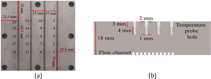
The temperature acquisition system was adopted to gather the temperature information of PEMFC. A total of 20 temperature detection points were arranged as depicted in Figure 11. The mean cell temperature is defined as the average temperature of 20 thermocouples. The maximum temperature difference (ΔTmax) and temperature uniformity index (TUI) are adopted to characterize the temperature distribution uniformity. The cooling efficiency (εc) of PEMFC can be determined through utilizing the proportion of Q1 to Qhe [19]. ΔTmax, TUI, and εc are expressed as below:
Figure 11.
Exact locations of thermocouples.
ΔTmax=Tmax−Tmin−ΔTiniE4
Tave=Σn=1NTnNE5
TUI=Σn=1NTn−TaveNE6
εc=Q1QheE7
Note that Tmax and Tmin are designated as the maximum and minimum temperatures recorded by 20 thermocouples, Tave is referred as the average temperature calculated from these 20 thermocouples, and ΔTini is used to define the initial temperature difference of PEMFC before the start of the experiment that consistently remains below 0.2°C.
5.2 Influence of metal foam flow field on thermal management of air-cooled PEMFC
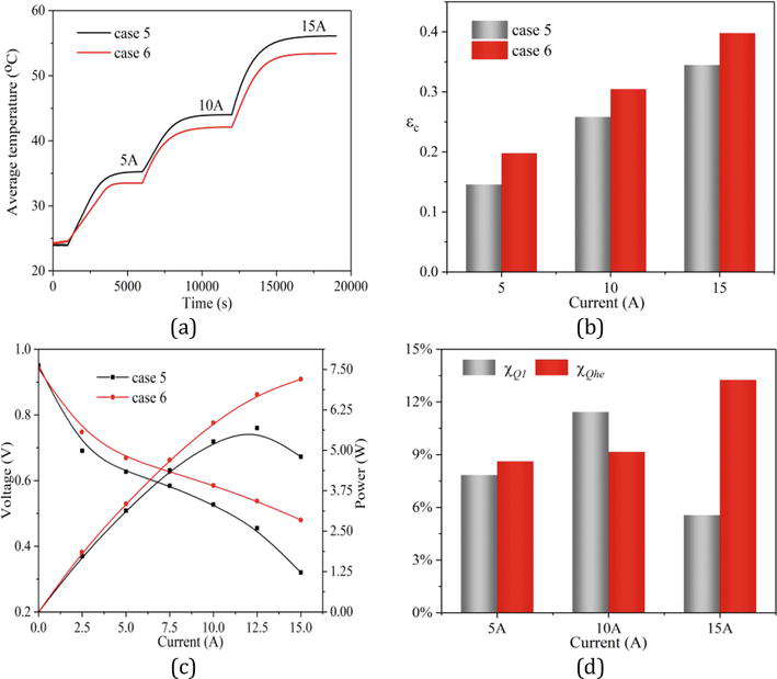
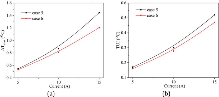
In this subsection, two cases, namely, cases 5 and 6, are chosen to examine the influence of metal foam flow field on the thermal management of air-cooled PEMFC. According to the data from Figure 12(a, b), case 6 gains a greater cooling efficiency in comparison with case 5. The primary cause comprises the following two factors: (1) The significant mixing effect of metal foam leads to an improvement in the forced convective heat transfer in fuel cell; (2) according to Figure 12(c), the output voltage of case 6 is greater in comparison with that of case 5 particularly when the operation current is located in medium and high regions; this observation suggests a notable reduction in ohmic loss. The explanation for this phenomenon lies in a better capability to retain water of metal foam, which has a positive impact on the proton transport efficiency of the proton exchange membrane. The results of Peng et al. [20] also emphasized this correlation. The improvement in the performance of PEMFC indicates a decrease in the heat produced from the electrochemical reaction. For conducting a more thorough examination of the influences of these two elements on the thermal management of air-cooled PEMFC, in comparison with case 5, the enhancement rate in forced convective heat transfer (χQ1) and the decrease rate in the generated heat (χQhe) for case 6 are depicted in Figure 12(d). The computing means for χQ1 and χQhe are presented in Eq. (8). It is worth noting that in the case of current below 10 A, there is minor variance between χQ1 and χQhe. However, χQhe is significantly larger than χQ1 under current of 15 A, meaning that at high current, employing metal foam flow field effectively reduces the heat generated from the electrochemical reaction process. The findings are in line with the outcomes introduced by Kang et al. [12]. Based on Figure 13(a, b), it can be observed that in comparison with case 5, case 6 has smaller ΔTmax and TUI, demonstrating that applying metal foam in the cathode side can help homogenize the temperature distribution of PEMFC, owing to the significant mixing effect.
Figure 12.
(a) Cell temperature over time; (b) comparison of the cooling efficiency; (c) polarization curves; (d) variation rates of Q1 and Qhe of case 6 in comparison with those of case 5.
Figure 13.
(a, b) temperature uniformities of different cases.
χQ1/Qhe=β6Q1/Qhe−β5Q1/Qheβ5Q1/Qhe×100%E8
where βQ1/Qhe is defined as the value of forced convective heat transfer or the heat produced from the electrochemical reaction process.
5.3 Influence of width of metal foam flow field
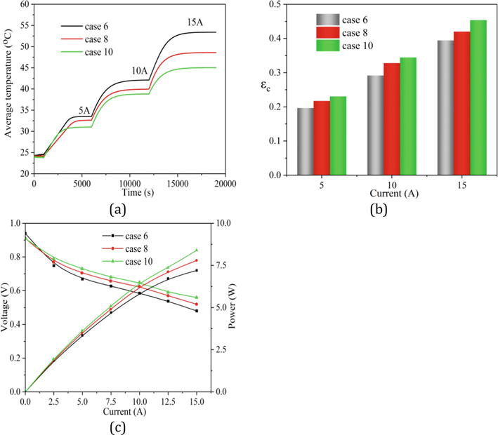
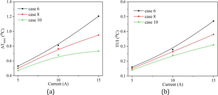
In this subsection, the study focused on investigating the influence of the width of metal foam on the thermal management of air-cooled PEMFC. Cases 6, 8, and 10 are analyzed. Figure 14(a, b) depict the average temperatures and cooling efficiencies of three cases at various currents. The results clearly demonstrate that case 10 outperforms the other two cases in terms of the thermal management. When raising the width from 1 mm (case 6) to 5 mm (case 10) with a current of 15 A, the average temperature of air-cooled PEMFC decreases by 8.4°C and the cooling efficiency increases by 14.7%, which means that the thermal management capability can be boosted through raising the width of metal foam. Furthermore, when maintaining a fixed rib width of 1 mm, raising the width of metal foam enlarges the contact area between the MEA and metal foam flow field, resulting in an improvement in the distribution uniformity of air as well as cell performance. As a result, less heat is generated from electrochemical reaction, as supported by the polarization curves depicted in Figure 14(c). In addition, the rise of the metal foam width also results in more even distribution of air on the MEA, leading to the homogeneity enhancement of the temperature distribution as depicted in Figure 15(a, b).
Figure 14.
(a) Cell temperature over time; (b) comparison of the cooling efficiency; (c) polarization curves.
Figure 15.
(a, b) temperature uniformities of different cases.
5.4 Influence of height of metal foam flow field
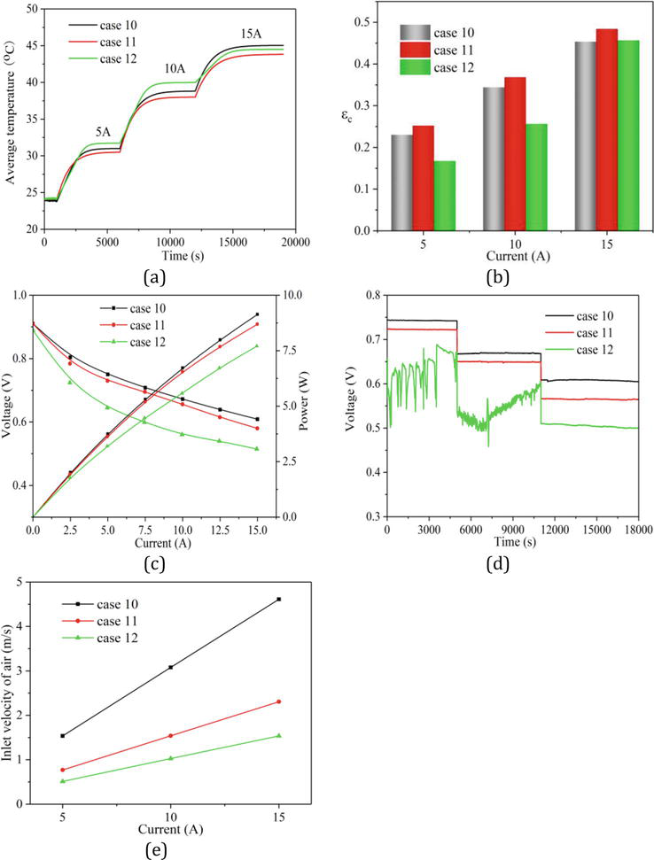
In this subsection, cases 10, 11, and 12 are chosen for analyzing the influence of the height of metal foam on the thermal management of air-cooled PEMFC. Observing from Figure 16(a, b), it is revealed that when current is lower than 10 A, case 12 exhibits the lowest cooling efficiency compared to cases 10 and 11. However, when current is further increased from 10 A to 15 A, case 12 experiences a significant increase in the cooling efficiency and becomes comparable to cases 10 and 11. In order to exemplify this point, Figure 16(c, e) are provided. From Figure 16(c), case 12 has the lowest performance, resulting in more waste heat generation. The operation voltage stabilities of different cases are depicted in Figure 16(d). It is observed that when current is lower than 10 A, case 12 exhibits instability. Nevertheless, the operation stability of case 12 experiences a significant enhancement with a current of 15 A. The primary factor lies in the fact that in comparison to case 10 and case 11, the air inlet velocity of case 12 is lower as illustrated in Figure 16(e). In the cases where current is lower than 10 A, the generated water from electrochemical reaction in case 12 cannot be effectively discharged by the airflow, leading to the operation instability. However, at current of 15 A, the increased inlet velocity of air allows for efficient water discharge, leading to the improved operation stability as well as output voltage in case 12. Furthermore, case 12 exhibits the best mixing effect in comparison with case 10 and case 11. As a result, the cooling efficiency of case 12 experiences a significant enhancement at current of 15 A. Among the three cases, case 11 shows the highest cooling efficiency, suggesting that for case 11, the benefits of raising the height of metal foam outweigh potential unfavorable consequences.
Figure 16.
(a) Cell temperature over time; (b) comparison of the cooling efficiency; (c) polarization curves; (d) voltage over time; (e) air inlet velocities of three cases.
This chapter focuses on the experimental investigation of the design strategy for metal foam flow field in different types of PEMFC. The influence of the arrangement of metal foam flow field on the performance and water management of liquid-cooled PEMFC was experimentally examined. Additionally, the structural characteristics of metal foam were optimized to enhance the water management and cell performance. Furthermore, in air-cooled PEMFC, the influence of metal foam flow field on the thermal management was also explored. On the basis of the exhausted experiments, the following conclusions have been drawn:
Under low RH, metal foam flow field demonstrates the capability to retain water, which is essential for wetting the membrane and enhancing the cell performance. Conversely, under high RH, employing metal foam flow field in the cathode side increases the possibility of water flooding, thereby impacting the liquid-cooled PEMFC performance negatively. Interestingly, when only the anode side utilizes metal foam flow field, there is no instance of the water flooding phenomenon, leading to an improved cell performance.
Under the operating conditions with complete relative humidity and a constant current density of 1.5 A/cm2, liquid-cooled PEMFC utilizing traditional straight flow field in the cathode side demonstrates steady current density and voltage throughout a 3-hour operation. However, when utilizing metal foam flow field in the cathode side, PEMFC experienced slight flooding within 105 minutes, leading to a slight degradation in voltage. Subsequently, the voltage decayed quickly. Furthermore, as relative humidity decreases, the crucial flooding times are gradually delayed.
Performance enhancement in liquid-cooled PEMFCs is observed with an increase in metal foam compression rate in the cathode side. Additionally, once the compression rate in the cathode side exceeds 0.69, the operation voltage demonstrates complete stability during 3-hour operation.
Regarding PPI of metal foam, it is intriguing to observe that optimal PPI, namely, 75, is obtained for the cathode side. This is attributed to the synergistic influence between the water management and gas distribution of metal foam flow fields with various PPIs.
The implementation of metal foam as cathode flow field for air-cooled PEMFC can effectively enhance its thermal management capability. Moreover, the implementation of metal foam can help even out the temperature distribution owing to its mixing effect for reactants.
Enhancing the width of metal foam results in better thermal management for air-cooled PEMFC. In the case where the height is fixed at 1 mm and the width rises from 1 to 5 mm, the cell temperature lowers by 8.4°C, accompanied by a 14.7% increase in the cooling efficiency at current of 15 A.
When the width of metal foam flow field is fixed at 5 mm, raising the height of metal foam from 1 to 2 mm results in a slight improvement in the cooling efficiency of air-cooled PEMFC. However, a further increase in the height to 3 mm leads to a minor water flooding phenomenon due to the low inlet velocity under current below 10 A.
This work is supported by National Natural Science Foundation of China (Nos. 52276184, 52176062, 51976055, 52076072) and the Science and Technology Innovation Program of Hunan Province (2020RC4040, 2021GK2017).
1.Barelli L, Bidini G, Ottaviano A. Optimization of a PEMFC/battery pack power system for a bus application. Applied Energy. 2012;97:777-784. DOI: 10.1016/j.apenergy.2011.11.043
2.Kang S, Min K. Dynamic simulation of a fuel cell hybrid vehicle during the federal test procedure-75 driving cycle. Applied Energy. 2016;161:181-196. DOI: 10.1016/j.apenergy.2015.09.093
3.Wan Z, Quan W, Yang C, Yan H, Chen X, Huang TM, et al. Optimal design of a novel M-like channel in bipolar plates of proton exchange membrane fuel cell based on minimum entropy generation. Energy Conversion and Management. 2020;205:112386. DOI: 10.1016/j.enconman.2019.112386
4.Cai G, Liang Y, Liu Z, Liu W. Design and optimization of bio-inspired wave-like channel for a PEM fuel cell applying genetic algorithm. Energy. 2020;192:116670. DOI: 10.1016/j.energy.2019.116670
5.Chen H, Guo H, Ye F, Ma CF. Modification of the two-fluid model and experimental study of proton exchange membrane fuel cells with baffled flow channels. Energy Conversion and Management. 2019;195:972-988. DOI: 10.1016/j.enconman.2019.05.071
6.Yan X, Guan C, Zhang Y, Jiang K, Wei G, Cheng X, et al. Flow field design with 3D geometry for proton exchange membrane fuel cells. Applied Thermal Engineering. 2019;147:1107-1114. DOI: 10.1016/j.applthermaleng.2018.09.110
7.Yang C, Nakayama A. A synthesis of tortuosity and dispersion in effective thermal conductivity of porous media. International Journal of Heat and Mass Transfer. 2010;53:3222-3230. DOI: 10.1016/j.ijheatmasstransfer.2010.03.004
8.Nakayama A, Ando K, Yang C, Sano Y, Kuwahara F, Liu J. A study on interstitial heat transfer in consolidated and unconsolidated porous media. Heat and Mass Transfer. 2009;45(11):1365-1372. DOI: 10.1007/s00231-009-0513-x
9.Afshari E, Mosharaf-Dehkordi M, Rajabian H. An investigation of the PEM fuel cells performance with partially restricted cathode floe channels and metal foam as a flow distributor. Energy. 2017;118:705-715. DOI: 10.1016/j.energy.2016.10.101
10.Awin Y, Dukhan N. Experimental performance assessment of metal-foam flow fields for proton exchange membrane fuel cells. Applied Energy. 2019;252:113458. DOI: 10.1016/j.apenergy.2019.113458
11.Tseng CJ, Tsai BT, Liu ZS, Cheng TC, Chang WC, Lo SK. A PEM fuel cell with metal foam as flow distributor. Energy Conversion and Management. 2012;62:14-21. DOI: 10.1016/j.enconman.2012.03.018
12.Kang DG, Park C, Lim IS, Choi SH, Lee DK, Kim MS. Performance enhancement of air-cooled open cathode polymer electrolyte membrane fuel cell with inserting metal foam in the cathode side. International Journal of Hydrogen Energy. 2020;45:27622-27631. DOI: 10.1016/j.ijhydene.2020.07.102
13.Jo A, Ju H. Numerical study on applicability of metal foam as flow distributor in polymer electrolyte fuel cells (PEFCs). International Journal of Hydrogen Energy. 2018;43(30):14012-14026. DOI: 10.1016/j.ijhydene.2018.01.003
14.Bao Z, Niu Z, Jiao K. Numerical simulation for metal foam two-phase flow field of proton exchange membrane fuel cell. International Journal of Hydrogen Energy. 2019;44(12):6229-6244. DOI: 10.1016/j.ijhydene.2019.01.086
15.Bao Z, Wang Y, Jiao K. Liquid droplet detachment and dispersion in metal foam flow field of polymer electrolyte membrane fuel cell. Journal of Power Sources. 2020;480:229150. DOI: 10.1016/j.jpowsour.2020.229150
16.Shin DK, Yoo JH, Kang DG, Kim MS. Effect of cell size in metal foam inserted to the air channel of polymer electrolyte membrane fuel cell for high performance. Renewable Energy. 2018;115:663-675. DOI: 10.1016/j.renene.2017.08.085
17.Park JE, Hwang WC, Lim MS, Kim SJ, Ahn CY, Kim OH, et al. Achieving breakthrough performance caused by optimized metal foam flow field in fuel cells. International Journal of Hydrogen Energy. 2019;44:22074-22084. DOI: 10.1016/j.ijhydene.2019.06.073
18.Zhao J, Huang ZP, Jian BX, Bai XY, Jian QF. Thermal performance enhancement of air-cooled proton exchange membrane fuel cells by vapor chambers. Energy Conversion and Management. 2020;213:112830. DOI: 10.1016/j.enconman.2020.112830
19.Mohamed WANW, Talib SFA, Zakaria IA, Mamat AMI, Duad WRW. Effect of dynamic load on the temperature profiles and cooling response time of a proton exchange membrane fuel cell. Journal of the Energy Institute. 2018;91(3):349-357. DOI: 10.1016/j.joei.2017.02.006
20.Peng M, Chen L, Zhang RY, Xu WQ, Tao WQ. Improvement of thermal and water management of air-cooled polymer electrolyte membrane fuel cells by adding porous media into the cathode gas channel. Electrochimica Acta. 2022;412:140154. DOI: 10.1016/j.electacta.2022.140154
Written By
Zhongmin Wan, Yun Sun and Chen Yang
Submitted: 23 August 2023Reviewed: 30 November 2023Published: 03 January 2024