Open Access is an initiative that aims to make scientific research freely available to all. To date our community has made over 100 million downloads. It’s based on principles of collaboration, unobstructed discovery, and, most importantly, scientific progression. As PhD students, we found it difficult to access the research we needed, so we decided to create a new Open Access publisher that levels the playing field for scientists across the world. How? By making research easy to access, and puts the academic needs of the researchers before the business interests of publishers.
We are a community of more than 103,000 authors and editors from 3,291 institutions spanning 160 countries, including Nobel Prize winners and some of the world’s most-cited researchers. Publishing on IntechOpen allows authors to earn citations and find new collaborators, meaning more people see your work not only from your own field of study, but from other related fields too.
This chapter explores the profound impact of CO2 carbonation on the pore structure of cement and concrete. Carbonation, resulting from the reaction of CO2 with calcium hydroxide and calcium silicate hydrate in cement, is a complex process that affects the durability and performance of cement-based materials. In this chapter, the changes in pore structure of cement and concrete induced by carbonation are examined. Under low pressure CO2, cement carbonation leads to the formation of dense carbonation regions. For wellbore cement exposed to high pressure and high concentration of CO2, a calcite precipitation layer with very low porosity is formed in cement, and two highly porous layers due to dissolution of calcite and cement hydration products are formed at both sides of the calcite precipitation layer. For concrete exposed to atmospheric pressure CO2, carbonation causes hydration products to form CaCO3 and precipitate in pores. Different from wellbore cement, no distinct calcite precipitation layer is formed in concrete. However, for concrete exposed to 1 MPa CO2, excessive accumulation of CaCO3 eventually leads to expansion and cracking of pores, which causes the compressive strength of concrete to decrease after reaching the peak.
State Key Laboratory of Geomechanics and Geotechnical Engineering, Institute of Rock and Soil Mechanics, Chinese Academy of Sciences, Wuhan, Hubei, China
Manguang Gan
State Key Laboratory of Geomechanics and Geotechnical Engineering, Institute of Rock and Soil Mechanics, Chinese Academy of Sciences, Wuhan, Hubei, China
Quan Xue
State Key Laboratory of Geomechanics and Geotechnical Engineering, Institute of Rock and Soil Mechanics, Chinese Academy of Sciences, Wuhan, Hubei, China
*Address all correspondence to: lwzhang@whrsm.ac.cn
1. Introduction
The production and application of cement have a history spanning thousands of years. Cement, as a versatile material, has played a pivotal role in the development of civilizations, transforming architectural possibilities and shaping the built environment. The roots of cement can be traced back to ancient times when early civilizations utilized naturally occurring materials to bind structures together. In ancient Egypt, a rudimentary form of cement was created by mixing gypsum with lime. This mixture, known as plaster of paris, was used for construction purposes, including decorative applications and the bonding of stones [1]. Similarly, the Romans utilized a mixture of volcanic ash and lime, known as pozzolana, to construct enduring structures like temples and aqueducts [2].
The next significant advancement in cement technology occurred during the eighteenth and nineteenth centuries with the discovery of hydraulic cement. Before the eighteenth and nineteenth centuries, the main components of cement were lime, volcanic ash, gypsum, and other materials that stuck together when in contact with air. In 1756, British engineer John Smeaton formulated a new type of cement by combining limestone and clay, creating a material that hardened when in contact with water [3]. Smeaton’s hydraulic cement was a significant improvement over previous versions, providing increased durability and versatility. In 1796, James Parker produced hydraulic cement by burning clayey limestone. Subsequently, in 1824, Joseph Aspdin obtained a patent for “Portland cement,” inspired by the resemblance of his hardened cement to Portland stone. The invention of Portland cement marked the birth of a mature and scalable cementitious material [4]. Portland cement became immensely popular due to its ability to set and harden in wet conditions, making it ideal for various construction applications. The Industrial Revolution brought substantial advancements in cement production. In the mid-nineteenth century, the introduction of rotary kilns enabled the production of larger amounts of cement, fueling the expansion of infrastructure projects worldwide. In 1843, Isaac Charles Johnson, an English engineer, patented the process of adding gypsum to cement, further enhancing its strength and stability.
The turn of the twentieth century witnessed significant breakthroughs in cement production. In 1908, Henry-Louis Le Chatelier, a French chemist, developed the soundness test for cement, ensuring its quality and uniformity. Furthermore, advancements in grinding technology allowed for the production of finely ground cement, increasing its reactivity and setting time. In the early twentieth century, the development of more efficient manufacturing processes revolutionized cement production. These advancements led to the creation of modern Portland cement, which became the primary building material for the construction industry worldwide. Additionally, the advent of blended cements, such as fly ash and slag-based cements, further diversified the range of cement types available [3].
In recent years, the cement industry has witnessed a growing emphasis on sustainability and environmental responsibility. Researchers and manufacturers have been actively exploring alternative materials, such as supplementary cementitious materials (SCMs), to reduce the carbon footprint of cement production [5]. SCMs, including fly ash, slag, and silica fume, can partially replace traditional cement clinker, resulting in lower greenhouse gas emissions. Furthermore, advancements in cement technology have focused on improving the durability and strength of concrete. The development of high-performance concrete, self-healing concrete, and nano-engineered cementitious composites (NECs) has expanded the possibilities of construction, offering increased resistance to extreme conditions and minimizing maintenance requirements [6].
Cement and concrete stand as foundational elements in modern construction and infrastructure, playing an indispensable role in shaping the built environment. The applications of cement and concrete are vast and diverse, ranging from towering skyscrapers and expansive bridges to residential homes and intricate pavements. The durability, versatility, and cost-effectiveness of concrete have made it the backbone of urban development, providing stability and longevity to structures worldwide [7]. Cement and concrete are extensively used in constructing buildings, from residential homes and office complexes to industrial facilities and commercial spaces. They provide the structural integrity required for tall skyscrapers, bridges, dams, and other large-scale structures. Concrete is a preferred material for building highways, roads, and pavements due to its durability and resistance to heavy traffic loads. It offers a smooth and long-lasting surface for transportation networks. Many iconic bridges and tunnels are constructed using reinforced concrete due to its ability to withstand various environmental factors, such as water, corrosion, and seismic activity. Concrete is used in building dams, reservoirs, and other water-related infrastructure. Its impermeability helps in water containment and control, while its strength can withstand pressure from water. Cement has been widely used to construct wellbores for oil and gas exploitation purposes. Most wellbores (especially deep wells) need to be cemented to protect the casing and tubing from corrosion, as well as to prevent fluid migration along the exterior of wellbores [7]. For airport construction, concrete runways, taxiways, and aprons are crucial components of airports. Similarly, port facilities, including wharfs and docks, rely on concrete for their construction. Concrete is used for foundations, walls, floors, and roofs in housing construction. It offers fire resistance, thermal insulation, and noise reduction, contributing to safe and comfortable living spaces. Precast concrete elements, such as beams, columns, and panels, are manufactured off-site and assembled on-site, expediting construction processes. Stamped concrete, stained concrete, and various decorative finishes allow for artistic expression in both interior and exterior architectural designs. Concrete is used to build water treatment plants, reservoirs, and storage tanks, ensuring clean and safe water supply to communities. Nuclear power plants, wind turbine foundations, and electrical substations often rely on concrete for their construction due to its stability and resilience. Stadiums, arenas, and entertainment venues utilize concrete for their grandstands, seating areas, and structural components. Concrete can be employed in coastal protection structures, erosion control systems, and stormwater management infrastructure. Sidewalks, plazas, and public squares often use concrete for pedestrian pathways and outdoor seating areas. Concrete is used for building silos, barns, and other agricultural structures. Concrete has also been widely used in the construction of military bases, bunkers, and defensive structures. These applications showcase the indispensable role that cement and concrete play in shaping the modern world and meeting the diverse needs of society [8].
Portland cement is produced by heating a blend of limestone and clay, or similar materials with comparable compositions, to an ultimate temperature of approximately 1450°C. During this process, the blend fuses, leading to the formation of clinker nodules. The typical composition of clinker is approximately 67% calcium oxide (CaO), 22% silicon dioxide (SiO2), 5% aluminum oxide (Al2O3), 3% ferric oxide (Fe2O3), and 3% other components [9]. This clinker generally comprises four main phases: alite, belite, aluminate, and ferrite. Among these, alite (abbreviated as C3S) holds the utmost significance in normal Portland cement clinkers, constituting 50–70% of the clinker content. Belite (C2S) makes up around 15–30% of the clinker, aluminate (C3A) accounts for 5–10% of the clinker, while ferrite (C4AF) constitutes 5–15% of the clinker’s composition [9]. After mixing with water, alite, belite, aluminate, and ferrite react with water to produce various hydration phases. The primary hydration products of alite and belite are portlandite (Ca(OH)2) and calcium silicate hydrate (C-S-H). Table 1 shows typical mineral compositions in cement.
Compound
Chemical formula
Oxide composition
Notation
Content (wt%)
Primary hydration products
Notes
Tricalcium silicate
Ca3SiO5
(CaO)3·SiO2
C3S
50–70
Ca(OH)2 and C-S-H
Ensures the strength of cement at all stages of manufacture
Dicalcium silicate
Ca2SiO4
(CaO)2·SiO2
C2S
10–30
Ca(OH)2 and C-S-H
Responsible for final strength, hydrates slowly
Tricalcium aluminate
Ca3Al2O6
(CaO)3·Al2O3
C3A
8–12
Various AFm (Al2O3-Fe2O3-mono) and AFt (Al2O3-Fe2O3-tri) phases
Hydrates rapidly, contributing to the strength of cement at an early stage; adding gypsum can control setting
Tetracalcium aluminoferrite
Ca4Al2Fe2O10
(CaO)4·Al2O3·Fe2O3
C4AF
8–12
Various AFm (Al2O3-Fe2O3-mono) and AFt (Al2O3-Fe2O3-tri) phases
Slow hydration; little effect on physical properties
Table 1.
Components in Class G cement formulation and their functionality [9, 10].
The primary use of cement is to produce concrete. Concrete is a composite with cement, sand, aggregates (coarse bulks), and water. The combination of hydrated cement and aggregate gives concrete high mechanical strength, resulting in concrete becoming a widely used building material [11]. Cement itself is also widely used as a binding material. When mixed with water, cement can generate binding force and separate parts can be bonded together. Therefore, the steel is placed in concrete to increase the mechanical strength of material due to the binding force that cement can produce [12]. Another use of cement is for wellbore cementing, which is an important practice in oil and gas industry. Class G cement is the most popular wellbore cement with common applications in oil and gas wells, especially for high-pressure high temperature (HPHT) conditions and its compatibility with other additives. Class H cement is another commonly used oilwell cement. Compared with class G cement, class H cement has stronger retarding properties, making it ideal for cementing deep wells.
Cement and concrete are porous materials, and pores play a very important role in governing the water transport and strength properties of cement and concrete. The pore arrangement within cement-based materials comprises four distinct pore categories. These include: (a) gel pores, which are micro-sized pores spanning 0.5–10 nm; (b) capillary pores, representing mesopores with an average radius ranging from 5 to 5000 nm; (c) larger macropores resulting from deliberately entrained air; and (d) macropores arising from insufficient compaction [13]. In concrete, alongside the mentioned pores, cracks might develop at the interface between aggregate and mortar due to shrinkage. The gel pores, primarily sized at 1.5–2.0 nm, do not exert adverse effects on concrete strength through their porosity [13]; however, they are closely linked to creep and shrinkage. Conversely, capillary pores and other sizable pores notably contribute to strength reduction and diminished elasticity [14, 15, 16]. Therefore, when establishing an empirical correlation between concrete strength and porosity, the gel pores’ role in overall porosity and pore size distribution can be disregarded without introducing notable errors. Consequently, for evaluating pore system characteristics affecting strength, the porosimetry test’s maximum pressure should be adequate to trigger mercury intrusion into the tiniest capillary pore. In mercury porosimetry, a substantial portion of gel pores remains unintruded. Furthermore, sealed pores also remain unintruded. An additional limitation associated with mercury porosimetry is its focus on entry sizes rather than the authentic pore size linked to the ink bottle phenomenon [17]. Thus, the porosity calculated as mentioned earlier represents apparent porosity [13].
Different from cement, due to the presence of aggregates in concrete, the pore size distribution of concrete shows a complicated pattern. Concrete created using hydraulic cement binder can be considered a chemically bonded ceramic structure [13]. The cement’s hydration reaction generates a composite of solids and a pore framework [18], meaning pores are inherent to concrete. Inadequate compaction can also lead to pore formation in concrete. This pore structure significantly governs concrete’s essential attributes, particularly its strength [19, 20]. Well-compacted concrete containing dense, low-porosity aggregates can be envisioned as a multiphase substance, encompassing coarse aggregates within a mortar matrix. This matrix is composed of fine aggregates, solid cement hydrates, unhydrated cement, and the accompanying pore system [14]. However, the pore architecture in concrete’s mortar differs notably from pores in well-compacted mortar formulated independently with the same ingredient proportions. This discrepancy arises from transition zone pores located at the mortar-aggregate junction [21, 22].
The capillary porosity of hardened cement paste hinges on the water-to-cement ratio, with this ratio also influencing transition zone porosity in concrete [14]. With the established relationship between strength and water-to-cement ratio, the concrete strength can be linked with pore structure characteristics [18, 23]. These relationships effectively guide concrete mix design. While some of these equations consider air content and concrete hydration, they often overlook structural pores stemming from inadequate compaction and other factors. Furthermore, the concrete’s pore structure changes with hydration levels and chemical alterations due to aggressive environments [13].
Alternatively, a direct correlation could enable the estimation of in situ concrete strength based on the knowledge of its pore system features. However, for mix design purposes, the relationships between strength and water-to-cement ratio prove more practical. Key attributes of the pore system are porosity and pore size distribution, quantifiable through mercury intrusion porosimetry (MIP). Yet, MIP results are influenced by multiple factors, necessitating adjustments in the experimental approach [24, 25, 26]. Additionally, the smallest pore size that mercury can infiltrate depends on the maximum applied intrusion pressure. Thus, the porosity extent determinable by porosimetry rests on pore nature, the smallest anticipated pore size in the material, and the maximum intrusion pressure [25, 27].
2.1 Carbonation of cement and concrete by low pressure CO2
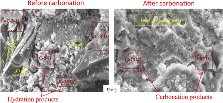
Under low pressure CO2 (0.1 MPa CO2 partial pressure or lower), the primary reaction of CO2 with cement is that CO2 reacts with Ca-bearing cement hydration products like calcium hydroxide and C-S-H to produce CaCO3. Since the CaCO3 production rate is usually higher than the consumption rates of calcium hydroxide and C-S-H, cement carbonation under low pressure CO2 causes a decrease in porosity of cement, and this process is beneficial for the integrity of cement. The distribution and morphology of hydration products and carbonation products in cement before and after reaction with low pressure CO2 obtained by high-magnification scanning electron microscopy (SEM) images are illustrated in Figure 1. CaCO3 accumulates in the primary pores inside the cement and causes the closure of some pores and cracks, especially the small diameter pores [29]. Finally, the porosity of cement decreases after carbonation in low pressure CO2 condition [30].
Figure 1.
Microstructure and morphology hydration products and carbonation products in cement before and after carbonation [28].
pH is the most important factor that governs the production of CaCO3 and consumption of calcium hydroxide and C-S-H. The formation of a large amount of calcium hydroxide and C-S-H during hydration creates an alkaline environment in the interior of the cement and concrete, with a pH of approximately 11 [31]. When CO2 is introduced, calcium hydroxide and C-S-H react with CO2 and the pH is reduced. Under low pressure CO2, the pH at the exterior of cement can drop to less than 9 [32], which is suitable for the precipitation of CaCO3. CaCO3 is stable under this pH, and the precipitation of CaCO3 in cement pores reduces the permeability of cement, as well as increases the strength of cement. In short, the carbonization of cement will lead to many chemical and mechanical changes in the cement slurry, the most significant being changes in strength, porosity, pore size distribution, and chemical properties. In addition, it can cause shrinkage and cracking of the gelling matrix [33].
The reaction between concrete and CO2 is almost the same as the reaction between cement and CO2, since cement is the active component in concrete that reacts with CO2. In general, only the cement experiences hydration during the curing process of concrete to produce hydration products like Ca(OH)2 and C-S-H [34]. Another important component in concrete is aggregates (usually natural sands, which are fine aggregates and gravels, which are coarse aggregates) [35]. Aggregates do not react with CO2. However, if steel is embedded in concrete and CO2 is able to reach the steel in concrete, the steel may get corroded by CO2, even when CO2 presents in relatively low pressure.
In general, cement hydration creates an alkaline environment inside concrete, which causes a passive film to form on the steel surface to protect steel from corrosion [36, 37]. The hydration products continue to react with CO2 to form CaCO3 to weaken the internal alkalinity of concrete with the continuous intrusion of CO2. When the internal alkalinity of concrete is lost, the contact of CO2 with the steel causes the corrosion of steel [38]. Under the influence of pore solution inside concrete, the steel reacts with CO2 to produce iron carbonate (FeCO3). With the process of reaction, FeCO3 is converted into Fe(III)-bearing products like Fe(OH)3 and Fe2O3 under the action of oxygen (O2) and water (H2O) [39]. Moreover, the corrosion products accumulate at the contact interface between steel and concrete, which causes the corrosion-induced cracks to occur owing to the lower density of corrosion products compared to the steel. The generation and expansion of induced cracks cause the separation of steel and concrete, which reduces the bonding strength of steel and concrete. Eventually, the structure of reinforced concrete is damaged and the strength of reinforced concrete is reduced under the influence of corrosion products, and the stability of reinforced concrete structure is affected by long-term influence of CO2.
Though the global cement production process emits large amounts of CO2, cement is able to absorb CO2 back from the air, and thus cement is also an important carbon sink. From 1930 to 2013, the global cement industry emitted 38.1 billion tons of CO2, while the carbon sink absorption by cement materials in the same period was as high as 16.5 billion tons, that is, 43% of the CO2 emissions of cement industry processes during this period were absorbed back by cement materials after use [40, 41].
2.2 Carbonation of cement and concrete by high pressure and high concentration of CO2
Under certain industrial practices like the exploitation of oil and gas from “sour” oil and gas reservoirs and geologic CO2 utilization and storage, the pressure of CO2 can be very high (e.g., 1–50 MPa). With the presence of water, the CO2 becomes very corrosive to well cement and can cause degradation of well cement. Given this high-pressure CO2, wellbore and its adjacent surroundings become chemically and mechanically unstable, posing a significant leakage risk to CO2 storage systems. Long-term interaction between CO2-saturated brine and wellbore cements, according to some experts, threatens wellbore integrity through calcium leaching [42]. During the degradation process of well cement, several geochemical reactions occur continuously because the cement is inherently unstable in aqueous environments rich in CO2 [43]. In this case, the cement’s sealing efficacy is determined by both environmental factors and the chemical composition and additives contained in it.
After exposure to carbonic acid under HPHT conditions, structural transformation, carbonation, and leaching are the primary mechanisms responsible for the physical and mechanical degradation of well cement. When C-S-H and Ca(OH)2 react with carbonic acid to form CaCO3, the process known as carbonation occurs. This process is quite similar to the carbonation process that occurs under low CO2 pressure condition. A major difference between low CO2 pressure condition and high CO2 pressure condition is the corresponding aqueous phase pH. The aqueous phase pH can drop to <3 when the aqueous phase pH is in equilibrium with a high-pressure CO2 phase (i.e., 1 MPa or higher). Under this low-pH condition, leaching occurs as the result of calcium ions migrating to the aggressive solution, which results in a progressive dissolution of cement paste [42, 44]. Significant cement leaching when exposed to carbonic acid under high CO2 pressure conditions is not observed when cement is exposed to carbonic acid under low CO2 pressure conditions (0.1 MPa CO2 partial pressure or lower).
When wellbore cement is exposed to brine containing CO2, the mechanical behavior of the cement is determined by the pace at which two competing mechanisms are at work: carbonation and leaching [45]. Carbonation drives the reaction front forward, whereas leaching occurs behind it. The fundamental reaction mechanisms are described as follows. The following chemical reactions occur when CO2 dissolves in brine solution and attacks wellbore cement [46].
Step 1 is the formation of carbonic acid: As shown in Eq. (1), when CO2 goes into a subsurface storage formation, it dissolves in the brine that’s left over, generating carbonic acid (H2CO3). This results in a considerable decrease in pH [47].
CO2+H2O↔H2CO3↔H++HCO3-↔2H++CO32-E1
Step 2 is the carbonation of the cementitious compounds: Carbonic acid primarily interacts with portlandite (Ca(OH)2) in the cement matrix, converting it into calcium carbonate and water.
Carbonation of calcium hydroxide.
Ca(OH)2+2H++CO32−→CaCO3+2H2OE2
This reaction, if not overreacted, benefits the wellbore’s mechanical properties. Calcite, in particular, can increase the mechanical strength of the cement layer while decreasing porosity, resulting in a decrease in permeability, which will decrease the potential for CO2 leakage [42].
where C-S-C is the calcium silicate carbonate group.
The rapid carbonation of portlandite occurs at 107°C and up to 177°C with abundant presence of CO2, precipitating CaCO3 that may apply stress on surrounding cement, which results in a drop in mechanical strength. Therefore, moderate carbonation is beneficial for the cement’s mechanical properties, while excessive carbonation impairs the mechanical strength of cement.
Step 3 is leaching out of calcium carbonates: The reaction between CaCO3 and CO2 created water-soluble Ca(HCO3)2 (Eq. (5)), and the continuous dissolution of Ca(HCO3)2 increased the cement’s porosity throughout the later stages of carbonation.
CaCO3(s)+H2CO3(aq)→Ca(HCO3)2(aq)E5
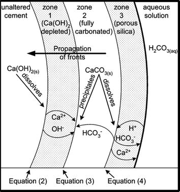
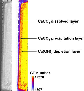
As shown in Figure 2, the relationship between the inward diffusion of carbonated water and Ca2+ diffusion out of the cement is illustrated, along with the precipitation and dissolution of calcium carbonate. Normally, the consumption of portlandite occurs first and then the reaction involving C-S-H follows. Due to the presence of multiphasic components, many complex reactions may occur simultaneously, and the illustrated reactions in Figure 2 are simplified reactions. A schematic of three distinctive layers as a result of CO2 and wellbore cement interaction is shown in Figure 2 and a computed tomography (CT) scanning image showing the three layers is provided in Figures 3.
Figure 2.
The relationship between the inward diffusion of carbonated water and Ca2+ diffusion out of the cement, along with the precipitation and dissolution of calcium carbonate [48].
Figure 3.
Computed tomography (CT) scan image showing degradation of well cement and formation of three distinctive layers by CO2 under geologic CO2 sequestration conditions.
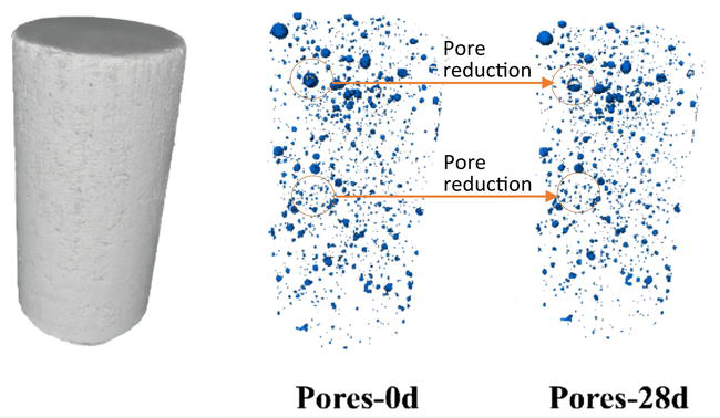
The increase of CO2 pressure and concentration raises the carbonation reaction rate of cement-based materials, which causes a large amount of CaCO3 to form and accumulate in pores. In the initial stage of carbonation, the precipitation of CaCO3 in pores makes the structure dense and reduces the porosity of cement-based materials, as shown in Figure 4. However, when CaCO3 precipitation reaches the threshold value that the concrete can bear, the pores may be damaged by excessive CaCO3 precipitation to produce microcracks [30]. Moreover, C-S-H decalcification may induce shrinkage during the carbonation reaction, and the shrinkage can also cause the generation of microcracks in cement-based materials [49]. When microcracks are generated inside cement-based materials, the material structure is destroyed and the penetration of CO2 into cement-based materials becomes easy. Meanwhile, more hydration products come into contact with CO2 to produce more CaCO3. A large amount of CaCO3precipitation further promotes the expansion of microcracks. Finally, the structural failure and strength loss occur in cement-based materials caused by excessive carbonation [50, 51]. Under the influence of high pressure and high concentration of CO2, cement-based materials are prone to excessive carbonation, which induces the porosity to decrease but weakens the strength of cement-based materials.
Figure 4.
Computed tomography (CT) scan image showing porosity reduction of cement-based materials by CO2.
Wellbore cement’s physical and mechanical properties are strongly influenced by temperature when used in a CO2-rich environment. Previous research has demonstrated that Class G wellbore cement becomes stronger in mechanical strength while becoming less porous and permeable at 107°C [34]. When the carbon capture and storage (CCS) wellbores are permanently plugged, it is important to consider the durability of cement at elevated temperatures. However, when CO2 is injected into a wellbore, the temperature significantly drops due to the Joule-Thomson effect, so the wellbore cement needs to withstand extreme temperature variation. This temperature drop is applicable when either continuous injection or cyclic intermittent injection procedures are followed.
The CO2 leakage risk through wellbore cement has been considered in large-scale risk assessment models. Viswanathan [52] developed a hybrid system level model, CO2-Predicting Engineered Natural Systems (CO2-PENS), for the assessment of wellbore leakage at a geologic CO2 sequestration site. Through the integration of information from laboratory experiments at the process level and field observations/experiments at the process level, the model provides a science-based prediction approach. This CO2-PENS model can not only be used to screen potential sequestration sites but can also be used as a tool for assessing individual sites’ performance as detailed site-specific data become available. Another widely used wellbore CO2 leakage risk evaluation code is WellRisk, which is based on drift flux method. The drift flux method was first developed by Zuber and Findlay [53], assuming that the flow rate of CO2 in a two-phase flow is a function of the mixed flow rate and the “drift flow rate” (i.e., the flow rate at which CO2 bubbles rise in a stationary liquid by buoyancy) in the two-phase flow [54].
WellRisk offers several advantages over CO2-PENS. Notably, it eliminates the need for inputting the wellbore permeability, effectively resolving the challenge of obtaining accurate permeability coefficient data. Furthermore, the drift flux model adopted by WellRisk mimics the realistic migration characteristics of fluids within the wellbore, resulting in higher calculation accuracy compared to the permeability coefficient method adopted by CO2-PENS.
Combination of CT and nanoscale SEM to investigate the pore structure evolution of cement exposed to CO2.
The size of the pores contained in cement is mostly between microns and nanometers, and the use of ordinary CTs with a resolution of microns to millimeters is not enough to directly characterize the pore structure of cement. In short, ordinary CTs can only provide the sample-scale trend of pore structure evolution in cement. Due to the limitation of CT scan resolution, the structural evolution of individual nanopores in cement after reaction with CO2 cannot be characterized by ordinary CT. In order to show the pore structure evolution of wellbore cement after CO2 corrosion from both sample scale and pore scale, it is necessary to combine CT scanning and high-resolution observation techniques (such as nanoscale SEM). Nanoscale scanning electron microscopy can reveal the structure of individual pores in a small area, which is very helpful in understanding the pore structure evolution of cement and concrete induced by carbonation.
Development of new cement additives to mitigate CO2-induced cement degradation.
Wellbore cement is chemically unstable under CO2-rich conditions because exposure of its hydration products to CO2 can cause physicochemical changes that are harmful to the cement matrix. The physicochemical changes can finally lead to cement degradation and loss of cement integrity. In order to enhance the performance of wellbore cement in CO2-rich environment, additives must be added to the cement to enhance the corrosion-resisting performance of wellbore cement. To improve the resistance of cement to CO2 corrosion, researchers have developed a variety of additives that can be incorporated into wellbore cement, such as volcanic ash, fiber, self-healing additives, nanoparticles, etc., and the development of economically suitable additives with effective resistance to CO2 corrosion is a promising research topic.
CO2-accelerated curing of concrete
Cement-based materials react with CO2 through cement hydration products such as calcium hydroxide to produce stable calcium carbonate. CO2-accelerated curing of concrete refers to the introduction of CO2 to the production process of concrete, which can reduce CO2 emissions and enhance the strength of concrete, mainly because the addition of CO2 can produce more calcium carbonate during the cement hardening process, thereby increasing the strength of cement. Therefore, CO2-accelerated curing of concrete is also an area that researchers are currently focusing on.
This chapter introduces the development history of cement and concrete, and analyzes the evolution of pore structure of cement and concrete by CO2 carbonation. The results show that under low pressure CO2, cement carbonation leads to the formation of a dense CaCO3-rich area, resulting in reduced cement permeability and increased cement strength. For wellbore cement exposed to high pressure and high concentration of CO2, a low-porosity calcite deposition layer is formed in the cement, and two highly porous layers due to the dissolution of calcite and hydration products are formed on both sides of the calcite deposition layer. For concrete exposed to atmospheric pressure CO2, carbonation causes hydration products to form CaCO3 and precipitate in the pores, reducing pore volume and total porosity. For concrete exposed to high-pressure CO2, excessive accumulation of CaCO3 eventually leads to pore expansion and cracking, resulting in a decrease in compressive strength after the compressive strength reaches its peak. The chapter also presents recent topics of interest, including the characterization of the nano- and microscopic pore structure of cement exposed to CO2 using nanoscale SEM scanning combined with microcomputed tomography (micro-CT), the development of high-performance cement additives to resist CO2 corrosion, and CO2-accelerated curing of concrete. In summary, an in-depth understanding of the pore structure changes after carbonation of cement and concrete is important for advancing research on cement-based materials, so as to build safe, green, and sustainable infrastructure.
The authors are grateful for the funding support provided by the National Natural Science Foundation of China (Grant No. 42172315) and the Science and Technology Plan Project of Sichuan Province (2022YFSY0018).
1.Cuezva S, Benavente D, Ivars J, Galan JM. Composition, uses, provenance and stability of rocks and ancient mortars in a Theban Tomb in Luxor (Egypt). Materials and Structures. 2016;49:941-960. DOI: 10.1617/s11527-015-0550-5
2.Palomo A, Monteiro P, Martauz P, Bilek V, Fernandez-jimenez A, De Ciencias I, et al. Hybrid binders: A journey from the past to a sustainable future (opus caementicium futurum). Cement and Concrete Research. 2019;124:105829. DOI: 10.1016/j.cemconres.2019.105829
3.Science Museum. Building the Modern World: Concrete and Our Environment [Internet]. 2021. Available from: https://www.sciencemuseum.org.uk/objects-and-stories/everyday-wonders/building-modern-world-concrete-and-our-environment
4.Britannica. History of Cement [Internet]. 2023. Available from: https://www.britannica.com/technology/cement-building-material/History-of-cement
5.Ashby MF. Materials and Sustainable Development. 2nd ed. Butterworth Heinemann: Oxford; 2023. 565 p. DOI: 10.1016/C2021-0-00557-5
6.Han B, Ding S, Wang J, Ou J. Nano-Engineered Cementitious Composites: Principles and Practices. Singapore: Springer; 2018. 731 p. DOI: 10.1007/978-981-13-7078-6
7.Yousuf N, Olayiwola O, Guo B, Liu N. A comprehensive review on the loss of wellbore integrity due to cement failure and available remedial methods. Journal of Petroleum Science and Engineering. 2021;207:109123. DOI: 10.1016/j.petrol.2021.109123
8.Civil Engineering. Uses of Cement [Internet]. 2023. Available from: https://civiltoday.com/civil-engineering-materials/cement/46-uses-of-cement#:~:text=It is used in mortar for plastering%2C masonry,roofs and constructing lintels%2C beams%2C stairs%2C pillars%2C etc
9.Taylor HFW. Cement Chemistry. 2nd ed. London: Thomas Telford Publishing; 1997. 439 p. DOI: 10.1680/cc.25929
10.Mangadlao JD, Cao P, Advincula RC. Smart cements and cement additives for oil and gas operations. Journal of Petroleum Science and Engineering. 2015;129:63-76. DOI: 10.1016/j.petrol.2015.02.009
11.Newell P. An ancient battle between environment and concrete. Nature Reviews Chemistry. 2021;5:513-514. DOI: 10.1038/s41570-021-00315-z
12.Choi Y, Yuan RL. Experimental relationship between splitting tensile strength and compressive strength of GFRC and PFRC. Cement and Concrete Research. 2005;35:1587-1591. DOI: 10.1016/j.cemconres.2004.09.010
13.Kumar R, Bhattacharjee B. Porosity, pore size distribution and in situ strength of concrete. Cement and Concrete Research. 2003;33:155-164. DOI: 10.1016/S0008-8846(02)00942-0
14.Soroka I. Portland Cement Paste and Concrete. London: Macmillan; 1979. 338 p. DOI: 10.1007/978-1-349-03994-4
16.Brandt AM. Cement Based Composites: Materials, Mechanical Properties and Performance. London: E&FN Spon; 1995. 544 p. DOI: 10.1201/9781482265866
17.Diamond S. Mercury porosimetry: An inappropriate method for the measurement of pore size distributions in cement-based materials. Cement and Concrete Research. 2000;30:1517-1525. DOI: 10.1016/S0008-8846(00)00370-7
18.Nagaraj TS, Banu Z. Generalization of Abrams’ laws. Cement and Concrete Research. 1996;26:933-942. DOI: 10.1016/0008-8846(96)00065-8
19.Därr GM, Ludwig U. Determination of permeable porosity. Matériaux et Construction. 1973;6:185-190. DOI: 10.1007/BF02479032
20.Rostásy FS, Weiβ R, Wiedemann G. Changes of pore structure of cement mortars due to temperature. Cement and Concrete Research. 1980;10:157-164. DOI: 10.1016/0008-8846(80)90072-1
21.Winslow D, Liu D, Lafayette W. The pore structure of paste in concrete. Cement and Concrete Research. 1990;20:227-235. DOI: 10.1016/0008-8846(90)90075-9
22.Aguado A, Gettu R, Shah S. Concrete Technology: New Trends, Industrial Applications. London: E&FN Spon; 1994. 366 p. DOI: 10.1201/9781482271584
23.Popovics S. New formulas for the prediction of the effect of porosity on concrete strength. ACI Journal Proceedings. 1981;82:136-146. DOI: 10.14359/10321
24.Laskar MAI, Kumar R, Bhattacharjee B. Some aspects of evaluation of concrete through mercury intrusion porosimetry. Cement and Concrete Research. 1997;27:93-105. DOI: 10.1016/s0008-8846(96)00192-5
25.Winslow DN, Diamond S. A mercury porosimetry study of the evolution of porosity in Portland cement: Technical publication. ACI Journal Proceedings. 1970;5:564-585. DOI: 10.5703/1288284314510
26.Diamond S. A critical comparison of mercury porosimetry and capillary condensation pore size distributions of Portland cement paste. Cement and Concrete Research. 1972;2:148-151. DOI: 10.1016/0008-8846(72)90032-4
27.Kumar R. Strength and permeation quality of concrete through mercury intrusion porosimetry [thesis]. Delhi, India: Indian Institute of Technology Delhi; 1997. Available from: https://libcat.iitd.ac.in/cgi-bin/koha/opac-detail.pl?biblionumber=163559
28.Liang C, Lu N, Ma H, Ma Z, Duan Z. Carbonation behavior of recycled concrete with CO2-curing recycled aggregate under various environments. Journal of CO2 Utilization. 2020;39:101185. DOI: 10.1016/j.jcou.2020.101185
29.Ghahari SA, Ramezanianpour AM, Ramezanianpour AA, Esmaeili M. An accelerated test method of simultaneous carbonation and chloride ion ingress: Durability of silica fume concrete in severe environments. Advances in Materials Science and Engineering. 2016;2016:1-12. DOI: 10.1155/2016/1650979. Available from: https://www.hindawi.com/journals/amse/2016/1650979/
30.Zhao K, Liang Y, Ji T, Lu Y, Lin X. Effect of activator types and concentration of CO2 on the steel corrosion in the carbonated alkali-activated slag concrete. Construction and Building Materials. 2020;262:120044. DOI: 10.1016/j.conbuildmat.2020.120044
31.Ho DWS, Lewis RK. Carbonation of concrete and its prediction. Cement and Concrete Research. 1987;17:489-504. DOI: 10.1016/0008-8846(87)90012-3
32.Papadakis VG, Fardis MN, Vayenas CG. Effect of composition, environmental factors and cement-lime mortar coating on concrete carbonation. Materials and Structures. 1992;25:293-304. DOI: 10.1007/bf02472670
33.Šavija B, Lukovic M. Carbonation of cement paste: Understanding, challenges, and opportunities. Construction and Building Materials. 2016;117:285-301. DOI: 10.1016/j.conbuildmat.2016.04.138
34.Wang J, Niu D, Zhang Y. Microstructure and mechanical properties of accelerated sprayed concrete. Materials and Structures. 2016;49:1469-1484. DOI: 10.1617/s11527-015-0589-3
35.Ulm FJ, Constantinides G, Heukamp FH. Is concrete a poromechanics material?—A multiscale investigation of poroelastic properties. Materials and Structures. 2004;37:43-58. DOI: 10.1007/bf02481626
36.Brunet JPL, Li L, Karpyn ZT, Huerta NJ. Fracture opening or self-sealing: Critical residence time as a unifying parameter for cement–CO2–brine interactions. International Journal of Greenhouse Gas Control. 2016;47:25-37. DOI: 10.1016/j.ijggc.2016.01.024
37.Silva A, Neves R, De Brito J. Statistical modelling of carbonation in reinforced concrete. Cement and Concrete Composites. 2014;50:73-81. DOI: 10.1016/j.cemconcomp.2013.12.001
38.Liang C, Pan B, Ma Z, He Z, Duan Z. Utilization of CO2 curing to enhance the properties of recycled aggregate and prepared concrete: A review. Cement and Concrete Composites. 2020;105:103446. DOI: 10.1016/j.cemconcomp.2019.103446
39.De Motte R, Basilico E, Mingant R, Kittel J, Ropital F, Combrade P, et al. A study by electrochemical impedance spectroscopy and surface analysis of corrosion product layers formed during CO2 corrosion of low alloy steel. Corrosion Science. 2020;172:108666. DOI: 10.1016/j.corsci.2020.108666
40.Xi F, Davis SJ, Ciais P, Crawford-brown D, Guan D, Pade C, et al. Substantial global carbon uptake by cement carbonation. Nature Geoscience. 2016;9:880-883. DOI: 10.1038/NGEO2840
41.Mora P, Sanjuan MA. Sequestration of CO2 by concrete carbonation. Environmental Science & Technology. 2010;44:3181-3186. DOI: 10.1021/es903581d
42.Omosebi O, Maheshwari H, Ahmed R, Shah S, Osisanya S, Santra A, et al. Investigating temperature effect on degradation of well cement in HPHT carbonic acid environment. Journal of Natural Gas Science and Engineering. 2015;26:1344-1362. DOI: 10.1016/j.jngse.2015.08.018
43.Montegrossi G, Huet B, Vaselli O, Hern A, Virgili G. A study of wellbore cement alteration controlled by CO2 leakage in a natural analogue for geological CO2 storage. Applied Geochemistry. 2017;86:13-25. DOI: 10.1016/j.apgeochem.2017.09.010
44.Zhang J, Peng Z, Zou C, Chen D. Improving the carbonation resistance of cement stone for oil wells by a polymer with acid response characteristic. Journal of Petroleum Science and Engineering. 2018;164:382-389. DOI: 10.1016/j.petrol.2018.01.080
45.Duguid A, Scherer GW. Degradation of oilwell cement due to exposure to carbonated brine. International Journal of Greenhouse Gas Control. 2010;4:546-560. DOI: 10.1016/j.ijggc.2009.11.001
46.Marshdi QSR. Benefits of using mineral additives, as components of the modern oil-well cement. Case Studies in Construction Materials. 2018;8:455-458. DOI: 10.1016/j.cscm.2018.03.010
47.Abid K, Gholami R, Choate P, Hari B. A review on cement degradation under CO2-rich environment of sequestration projects. Journal of Natural Gas Science and Engineering. 2015;27:1149-1157. DOI: 10.1016/j.jngse.2015.09.061
48.Kutchko BG, Strazisar BR, Dzombak GV, Lowry DA, Thaulow N. Degradation of well cement by CO2 under geologic sequestration conditions. Environmental Science & Technology. 2007;41:4787-4792. DOI: 10.1021/es062828c
49.Auroy M, Poyet S, Le P, Torrenti J, Charpentier T, Moskura M, et al. Impact of carbonation on unsaturated water transport properties of cement-based materials. Cement and Concrete Research. 2015;74:44-58. DOI: 10.1016/j.cemconres.2015.04.002
50.Xue Q , Zhang L, Mei K, Wang L, Wang Y, Li X, et al. Evolution of structural and mechanical properties of concrete exposed to high concentration CO2. Construction and Building Materials. 2022;343:128077. DOI: 10.1016/j.conbuildmat.2022.128077
51.Xue Q , Zhang L, Mei K, Li X, Newell P, Wang Y, et al. CO2-induced evolution of chemical, structural and mechanical properties of reinforced concrete: A review. Construction and Building Materials. 2022;353:129069. DOI: 10.1016/j.conbuildmat.2022.129069
52.Stauffer PH, Kaszuba JP, Carey JW, Olsen SC, Keating GN, Kavetski D, et al. Development of a hybrid process and system model for the assessment of wellbore leakage at a geologic CO2 sequestration site. Environmental Science & Technology. 2008;42:7280-7286. DOI: 10.1021/es800417x
53.Zuber N, Findlay JA. Average volumetric concentration in two-phase flow systems. Journal of Heat Transfer. 1965;87:453. DOI: 10.1115/1.3689137
54.Pan L, Oldenburg CM, Wu Y, Pruess K. Wellbore flow model for carbon dioxide and brine. Energy Procedia. 2009;1:71-78. DOI: 10.1016/j.egypro.2009.01.012
Written By
Liwei Zhang, Manguang Gan and Quan Xue
Submitted: 31 August 2023Reviewed: 14 March 2024Published: 22 April 2024