Open Access is an initiative that aims to make scientific research freely available to all. To date our community has made over 100 million downloads. It’s based on principles of collaboration, unobstructed discovery, and, most importantly, scientific progression. As PhD students, we found it difficult to access the research we needed, so we decided to create a new Open Access publisher that levels the playing field for scientists across the world. How? By making research easy to access, and puts the academic needs of the researchers before the business interests of publishers.
We are a community of more than 103,000 authors and editors from 3,291 institutions spanning 160 countries, including Nobel Prize winners and some of the world’s most-cited researchers. Publishing on IntechOpen allows authors to earn citations and find new collaborators, meaning more people see your work not only from your own field of study, but from other related fields too.
In recent decades, many studies on flow and heat transfer in porous media have been conducted by researchers to take advantage of its high specific surface area and good heat transfer performance. What is more, the graded porous media have also drawn great attention since the graded arrangement enhances local heat transfer coefficient, so as to improve the overall heat transfer performance and temperature uniformity. The new forms of structure provide a new design of cooling system for some high-power heat sources, such as electronic components, compact heat exchangers, and hot components in aeroengine. In this chapter, the problems of channels filled with vertically graded porous media and axially graded porous media have been introduced, respectively. The flow and heat transfer characteristics of graded porous media have been studied based on porous media theory, considering the parameters of porosity, permeability, pore diameter, etc. The profiles of velocity and temperature vary with different porosity arrangements present. The maximum heat transfer coefficient was obtained for the case of high porosity at the center and low porosity near the wall. Furthermore, the possibility of application in the aeroengine cooling has been discussed.
School of Power and Energy, Northwestern Polytechnical University, Xi’an, China
Cunliang Liu*
School of Power and Energy, Northwestern Polytechnical University, Xi’an, China
Akira Nakayama
School of Power and Energy, Northwestern Polytechnical University, Xi’an, China
Faculty of Engineering, Shizuoka University, Hamamatsu, Japan
*Address all correspondence to: liucunliang@nwpu.edu.cn
1. Introduction
Porous media (e.g. metal foam) has drawn great attention due to its potential for application in various scenarios, such as compact heat sinks, regenerative heat exchangers, and combustor-incinerators [1]. Due to its high specific surface area, the metal foam matrix is regarded as a promising material and structure to improve energy absorption and heat transfer in hot component system. In past decades, many relative investigations were conducted theoretically and experimentally and reported for metal foam matrices [2, 3, 4, 5].
Functionally graded porous materials are those porous media with a gradual change of porosity (solidity) and pore size. Thanks to the recent advances in manufacturing technologies, the design and fabrication of such non-uniform structures have become possible. Since the concept of functionally graded materials was proposed in the literature [6] in the 1980s, the studies on making continuous changes in the composition, microstructure, porosity, and other properties have been continuously conducted, since these changes improved its mechanical performance or thermal performance in some reasonable ranges. In recent years, some ceramic-made functionally graded materials have been produced by using a position-dependent chemical composition [7].
The graded porous media may achieve a better heat transfer performance since the graded arrangement enhances local heat transfer coefficient, so as to improve the overall heat transfer performance and temperature uniformity. For example, we may consider some functionally graded metal foam structures that are under equal mean porosity. Firstly, the metal foam matrix may be arranged with higher porosity near the wall subject to constant heat flux and lower porosity in the core regions. This arrangement may create a higher velocity close to the wall and lower velocity in the core, which differs from a regular velocity profile in a channel. On the contrary, lower porosity near the wall may result in thicker thermal boundary layer, which prompts the thermal conductivity near the heated wall but weakens convective heat transfer. Therefore, each case of graded porosity arrangement brings favorable and unfavorable factors on heat transfer performance, but an optimal spatial distribution of the porosity may exist.
On the other hand, axially graded porous materials in a channel with lower porosity (i.e. higher metal volume fraction) in the entrance region and higher porosity in the exit region may further enhance the convective heat transfer coefficient in developing region, however, the convective heat transfer in the downstream maybe weaken because the temperature of the coolant air is increased by mixing. On the contrary, the higher porosity (i.e. lower metal volume fraction) in the entrance region and lower porosity in the exit region may enhance the heat transfer performance of the downstream, since the mixing of the coolant air improves its cooling quality in the downstream. Incidentally, the increase of the heat transfer rate downstream accelerated the heat transfer on the wall and improved the temperature uniformity over the wall.
Wang et al. [8] conducted numerical investigation on the heat transfer of a pipe embedded with functionally graded materials with larger diameter particles near the walls. Zheng et al. [9] have numerically evaluated the heat transfer performance of a pipe filled with a porous foam with radially variable sizes of particles under equal porosity. Bai et al. [10] analytically investigated the heat transfer performance of a channel filled with functionally graded foam matrix in a vertical direction from the central line to the heated walls. They concluded that the graded arrangement of foam matrices may achieve a substantial increase in heat transfer coefficient at the expense of an acceptable consume of pressure loss. Subsequently, Iasiello et al. [11] numerically investigated the effects of variable porosity and cell size on the thermal performance of functionally graded foams, whose porosity and cell size vary according to different power-law functions in the direction of normal to the wall. As a result, a 42% increase in Performance Evaluation Criterion (PEC) is found in foams that account for both variable porosity and cell size. Mauro et al. [12] carried out a comprehensive optimization framework to design a graded foam structure by mono-and multi-objective optimization method. They proposed optimum design parameters that achieve the best thermal performance as high as 1.5 performance evaluation criterion (PEC). Recently, Bai et al. [13] considered an occasion of heat transfer in a channel filled with axially graded porous materials to investigate the temperature distribution on the heated walls. They found that the wall temperature variation is quite sensitive to the axial gradient of the local porosity. Furthermore, the functionally graded foams with variable PPI enhance pool boiling heat transfer and that with linearly-variable porosity enhance heat transfer in phase change materials were presented by Xu and Zhao [14] and Yang et al. [15], respectively. In short, the enhancement of heat transfer by exploiting graded porous materials has been comprehensively substantiated.
With the increase of the demand on the large thrust of the engine, the temperature value of gas in front of turbine increases. For the military aircraft, the afterburner is adopted to increase the transient trust of the aeroengine. However, the gas temperature at the afterburning state far exceeds the limitation of the material. In this case, the graded porous structure may be useful to adjust the coolant distribution and to improve the temperature uniformity.
In this chapter, the flow and heat transfer in channels filled with graded porous materials (radially graded and axially graded) have been investigated, and the flow structures and heat transfer characteristics have been revealed for both cases with different parameters. The possibility of the application of graded porous structure in afterburner heat shield has been discussed.
2. Flow and heat transfer in a channel filled with vertically graded porous media
The analytical investigation of heat transfer characteristics of a channel filled with radially graded porous media has been conducted in this section. A series of graded metal foam matrices of the same solidity were arranged with their porosity either increasing or decreasing toward the heated walls following a parabolic function. As a result, the maximum heat transfer coefficient of the channel filled with a functionally graded metal foam matrix was achieved for the case that low porosity near the heated wall and high porosity in the central line, which is 20–50% higher than that of the uniform distribution of metal foam matrix. Therefore, the effectiveness of functionally graded metal foam matrices to achieve higher heat transfer coefficient with an acceptable pressure loss was substantiated.
2.1 Physical model and analysis
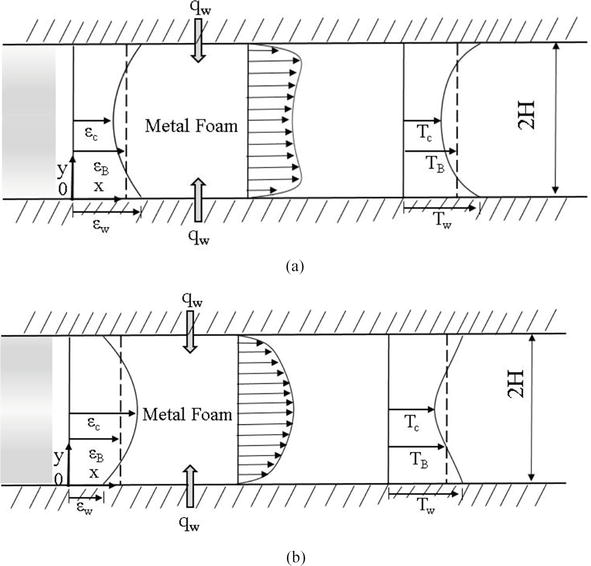
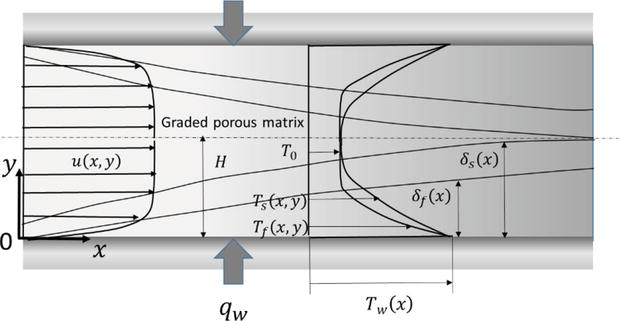
As illustrated in Figure 1, there are two cases of channels filled with a functionally graded metal matrix, one case has high porosity near the wall and low porosity in the core region of channel, the other case has reversed arrangement. Both upper and lower walls were subject to a constant heat flux qw. We mainly focus on the region of hydro-dynamically and thermally fully developed flow in these cases, because the developing region, which may take several hydraulic diameters, is short enough due to the addition of the metal foam matrix.
Figure 1.
Physical models of channels with graded porous media. (a) The case with high porosity near the wall and low porosity in the core and (b) the case with low porosity near the wall and high porosity in the core.
The volume-averaged version of the momentum equation was derived by exploiting the Brinkman-extended-Darcy momentum equation Eq. (1), likewise, the volume-averaged energy equations for the fluid and solid phases were obtained as Eqs. (2) and (3).
−dpdx+ddyμεdudy−μKu=0E1
ρfcpfu∂Tf∂x=∂∂yε∗kf+εkdis∂Tf∂y−hvTf−TsE2
∂∂y1−ε∗ks∂Ts∂y+hvTf−Ts=0E3
where u is the Dacian bulk velocity, which is related to the local porosity and intrinsic velocity. εy and Kε are porosity and permeability, respectively, which vary spatially across the channel in vertical direction(y), whose origin is located on the lower heated wall. Tf and Ts are the intrinsic volume average fluid and solid phase temperatures, respectively. hv is the volumetric interstitial heat transfer coefficient. In general, the thermal dispersion term is often expressed by the gradient diffusion hypothesis with the thermal dispersion conductivity kdis [16]. The concept of the effective porosity ε∗ was introduced to account for the tortuosity of the structure, which is theoretically given as
ε∗≡ks−keks−kf≅2+ε3E4
whereke is the effective stagnant thermal conductivity, which is given as
keε=ε∗kf+1−ε∗ks=2+ε3kf+1−ε3ksE5
The two energy equations, namely Eqs. (3) and (4), may be added to yield
ρfcpfu∂Tf∂x=∂∂yε∗kf+εkdis∂Tf∂y+1−ε∗ks∂Ts∂yE6
Then, Eq. (6) may be reduced under the local thermal equilibrium assumption and neglecting the comparatively small term of the thermal dispersion conductivitykdis for the case of aluminum-air combination [17] to
ρfcpfu∂T∂x=∂∂ykeε∂T∂yE7
Eq. (7) should be solved with the momentum Eq. (1) under the following boundary conditions:
For y=0:
u=0andqw=−keεw∂T∂yE8
For y=H:
∂u∂y=0and∂T∂y=0E9
The porosity of the functionally graded metal foam matrix in a channel varies following a parabolic function across the channel as follows:
εy=εc+εw−εc1−yH2E10
where the subscripts of w and c indicate the wall and the center of the channel, respectively.
As for the permeability, the correlation provided by Calmidi [18] for metal foam was adopted:
where Kε/H2 is function of the porosity, which typically ranges from 3 × 10⁻³ to 8 × 10⁻³.
Subsequently, the non-dimensional momentum equation and energy equation were solved using a standard Runge-Kutta-Gill scheme, with the following dimensionless boundary conditions:
u∗η=0=0E12
and
du∗dηη=1=0E13
Once the velocity profile was determined and fed into the energy Eq. (6), the following expression can be yielded by integrating from y = 0 to H
HρfcpfuBdTBdx=qwE14
where
TB=ρfcpf∫0HuTdyρfcpfuBE15
is the bulk mean temperature. Since dTB/dx=∂T/∂x for the thermally fully developed flow, the energy Eq. (6) simplifies to
u∗u∗B=ddηkeεkeεBdT∗dηE16
where
u∗B=∫01u∗dηE17
and
T∗=keεBT−TwqwHE18
are the dimensionless bulk mean velocity and local dimensionless temperature, respectively. Integrate the Eq. (16) from η=0 can attain
dT∗dη=∫0ηu∗u∗Bdη−1keεkeεBE19
The dimensionless temperature can be found by further integrating the foregoing Eq. (19) by using the Runge-Kutta-Gill scheme. The following boundary conditions on the temperature and its gradient on the wall are implemented:
T∗η=0=0anddT∗dηη=0=−keεBkeεwE20
Thus, the Nusselt number of our primary interest can be obtained from
The definition of NuH contains keεB accounted for the effect of increase in the effective thermal conductivity on the Nusselt number. It is meaningful to compare NuH for all cases of different weights, even for the case of the channel without a metal foam, based on the definition given by Eq. (21).
2.2 Velocity and temperature profiles
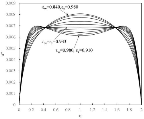
The dimensionless velocity profiles obtained for the metal foams of the same weight of εB = 0.933 were presented in Figure 2. The wall porosity εw varies from 0.840–0.980, and the case of εw = 0.933 corresponds to the case of uniform porosity metal foam. As we can see, the increase in the εw creates a higher velocity value close to the wall and lower velocity with a concave profile in the core region.
Figure 2.
Dimensionless velocity profiles.
To the contrary, the decrease of the εw results in a higher velocity value in the core region and lower velocity value near the wall comparing with the velocity distribution for the case of the uniform porosity. Naturally, more metal near the wall has favorable influence on conductive wall heat transfer, but more metal may block the near-wall flow, decreasing the flow velocity. Therefore, these favorable and unfavorable factors form a trade-off for the heat transfer enhancement.
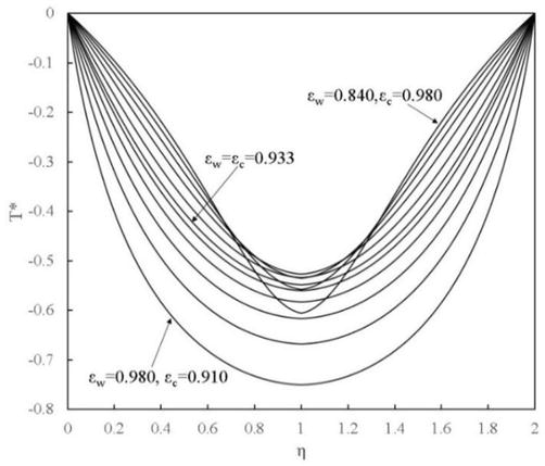
The corresponding dimensionless temperature profile for the case of ks/kf = 104 was shown in Figure 3, which assumes a combination of air and aluminum.
Figure 3.
Dimensionless temperature profiles.
As can be seen, the dimensionless temperature profile of the uniform porosity case of εw = εw = 0.933 has been presented and indicated. As increasing the value of εw, the dimensionless temperature gradient at the wall become steeper, which can also be expected from Eq. (20). While decreasing the εw, the dimensionless temperature profile near the wall changes its curvature to negative one, while the protrusion of the dimensionless temperature in the core becomes more extensive.
2.3 Heat transfer characteristics
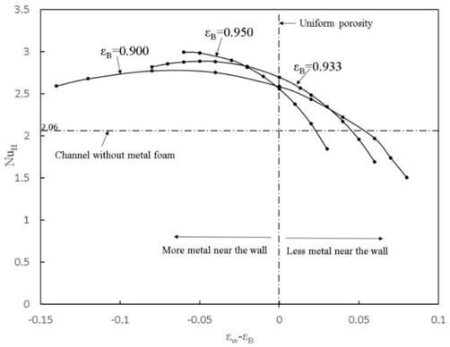
Figure 4 presents the curves of NuH against the porosity distribution for the given bulk mean porosity εB = 0.900, 0.933, and 0.950. The level of NuH for the channel without a metal foam, namely, NuH = 2.06, was also indicated. The figure indicates that the increase in the effective thermal conductivity enables the convective heat transfer coefficient in a channel filled with a metal foam to increase about 20–50% more than 2.06keεB/H. However, for the cases of positive εw-εB, the values of NuH go below the value 2.06.
Figure 4.
Nusselt number NuH against εw−εB.
As a result, the maximum values of NuH are found in the negative range of εw–εB, where the porosity of the functionally graded metal foam decreases toward the wall (i.e. more metal near the wall).
In comparison with the case of the channel without a metal foam, the addition of the metal foam achieves high heat transfer coefficient but at expense of a larger pressure drop, or pressure gradient −dp/dx, which can be related to its pumping power per unit axial length HuB−dp/dx as
−dpdx=1u∗BμH3HuB−dpdxE22
Thus, the pressure drop ratio in the channel with a metal foam to that of an empty channel (where u∗f=1/3) under equal pumping power is given by
Δp/Δpf=1/3u∗BE23
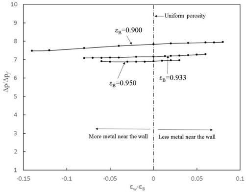
As shown in Figure 5, the pressure drop ratios for the corresponding three cases are presented. In comparison to the case of the channel without a metal foam, the addition of the metal foam matrix results in about 7–8 times increase in pressure drop under equal pumping power. Moreover, the bulk mean porosity of εB brings more sensitive effects than εw−εB.
Figure 5.
Pressure drop ratio ∆p/∆pf against εw−εB.
2.4 Conclusions
In this section, the heat transfer characteristics of forced convection in channels filled with functionally graded metal foam in vertical direction normal to the heated walls have been analytically investigated. The fully developed set of Brinkman-extended Darcy momentum equation and the energy equation associated with local thermal equilibrium assumption were taken into account. The porosity of parabolic distribution was assumed across the channel height. The integrated energy equation associated with momentum equation was solved by using the Rung-Kutta-Gill integration scheme. According to the analytical results, for the metal foams of the same weight, the maximum heat transfer coefficient can be obtained for the case of the high porosity in the core and low porosity near the wall, at the expense of an acceptable increase in pressure drop.
3. Flow and heat transfer in a channel filled with axiallygraded porous media
In this section, the problem of flow and heat transfer in a channel filled with axially graded porous materials based on local thermal non-equilibrium has been investigated to find a way to control its wall temperature distribution [13]. A series of axially graded foams under an equal solid fraction were considered. The porosity decreasing along the downstream of the channel following a power function of axial coordinate with an exponent of n was assumed. The Brinkman-Forchheimer extended Darcy model and the local thermal non-equilibrium assumption were exploited to obtain the velocity profiles and temperature distributions on the heated walls, respectively.
3.1 Physical model and analysis
A channel of height 2H filled with a fluid-saturated axially graded porous media subject to constant heat flux is presented in Figure 6.
Figure 6.
Channel model filled with an axially graded porous medium.
The indexes of δf and δs represent thermal boundary layer thicknesses for fluid phase and solid phase, respectively. Both the fluid phase thermal boundary layer and solid phase thermal boundary layer grow from the entrance to the downstream. However, the thermal boundary layer of solid grows thicker than that of the fluid due to the higher thermal conductivity of the solid than that of the fluid. In the present study, the thermally developing region of the entrance is focused so that δf and δs are less than half the channel height, H.
In the present case, the Brinkman-Forchheimer-extended Darcy model is still valid since the velocity change in such an axially variable porosity-arranged porous media is so moderate that the convective inertia terms are almost negligible. Hence, the velocity field can be determined from the momentum and continuity equations as follows:
−dpdx+μfεx∂2u∂y2−μfKxu−ρfbxu2=0E24
∂u∂x+∂v∂y=0E25
where u and v are the local volume average velocity components. p is the intrinsic pressure, μf is the fluid viscosity, Kx is the permeability, and b is the inertial coefficient. Moreover, x is the axial coordinate while y is the coordinate measured vertically from the lower wall surface of the channel.
Following Amiri and Vafai [19], the energy equations for the fluid phase and the solid phase can be given as
ρfcpf∂uTf∂x+ρfcpf∂vTf∂y=∂∂ykfex∂Tf∂y−hvxTf−TsE26
∂∂yksex∂Ts∂y+hvxTf−Ts=0E27
where kfe and kse are the effective thermal conductivities of the fluid and the solid, respectively. hv denotes the interstitial volumetric heat transfer coefficient.
Considering the symmetry of the geometry, the lower half of the channel is analyzed with corresponding boundary conditions given as follows:
where qwis the wall heat flux. Twx is the wall temperature.
According to Yi et al. [20], the Eq. (24) can be normalized by using the constant bulk velocity uB with axially variable porosity and permeability as
∂2∂η2uuB−εxDaxuuB−RebxuuB2=−−εH2μfuBdpdxE31
where
η=yHE32
Dax=KxH2Darcy numberE33
Rebx=εxρfbxH2uBμfE34
where Rebx is the Forchheimer Reynolds number based on the scale of length bH2. The following velocity profile uxη may be assumed with an unknown parameterζx:
uuB=ζ+1ζ1−1−ηζE35
which automatically satisfies the boundary conditions (29) and ∫01uuBdη=1. It is obvious that the case of ζ=2 in Eq. (35) denotes the fully developed profile in an empty channel flow, while for the case of ζ→∞, the velocity profile becomes the Darcy(plug) flow.
Evaluating Eq. (31) on the wall (at η=0) using the foregoing velocity profile (35), one obtains
−εH2μfuBdpdx=ζ2−1E36
Thus, Eq. (31) may be integrated across the channel from η=0 to 1 as
−∂∂ηuuBη=0−εDa∫01uuBdη−Reb∫01uuB2dη=−ζ2−1E37
Based on the Eq. (37) associated with the Eq. (31), a cubic equation for the unknown parameter ζ can be yielded as follows:
2ζ3−ζ2−2εDa+2Reb+5ζ−εDa+2Reb+2=0E38
The local value of the ζε/DaReb in this cubic equation can be easily evaluated by substituting the local values of εx/Dax andRebx. As for the root of the foregoing cubic equation, a highly accurate expression in a closed form based on the two asymptotes was obtained by Yi et al. [20]:
Eq. (39) reduces to the two distinct exact asymptotes as:
ζεDa0=1+9+4εDa2E40
and
ζ0Reb=3+25+16Reb4E41
Naturally, the velocity profile function with Eqs. (40) and (41) gives uuB=321−1−η2 for Daε→∞ (orReb→0) (i.e. empty channel) and uuB=1for Daε→0 (orReb→∞) (i.e. Darcy flow).
Once ζx is determined, the local friction coefficient may be estimated from
HρfuB2−dpdx=ζ2−1εReHE42
where
ReH=ρfuBHμfE43
is the Reynolds number based on uB and H.
The vertical velocity component vxη may be determined by substituting Eq. (31) into the continuity Eq. (25) as
which satisfies the boundary conditions (29). It is interesting to note that the velocity component v in the lower half of the channel is negative for the channel of dζdx > 0, which is met when either εDa=εxH2Kx or Reb=εxρfbxH2uBμf increases downstream, while the vertical velocity component v vanishes in the case of channels filled with uniform porous materials (i.e.dζdx=0).
For the thermally fully developed flows in a channel filled with a uniform porous medium, Nakayama et al. [4] obtained a temperature field under the L.T.E. assumption as
For the case of the channel filled with axially graded porous materials, analytical expressions for its wall temperature under the L.T.N.E. assumption were obtained by exploiting the above temperature profile (Eq. (45)) and velocity profile (Eq. (35)), which prevail across both fluid and solid thermal boundary layers (δf<δs<H):
These profiles satisfied the boundary conditions (29) and (30) and naturally recovered the fully-developed profile given by Eq. (45) as both δf∗ and δs∗ grow downstream to reach unity. The fluid bulk mean temperature TfB in the entrance region may be estimated using the profiles (35) and (46) as
Since the fluid phase thermal boundary layer is thinner in this entrance developing region, the velocity field across the thermal boundary layer may be described by a linearized velocity profile.
The interstitial heat transfer term hvxTf−Ts can be canceled by adding the energy Eqs. (26) and (27). Moreover, integrating the resulting equation across the channel and over the axial distance from 0 to x with the boundary conditions (28) and (29), the energy balance relationship can be obtained as follows:
is the Graetz number. Moreover, kref is a reference thermal conductivity.
For given properties of the graded porous materials, namely εxDax and Rebx=εxρfbxH2uBμf, the velocity profile parameter ζx can be determined from Eq. (37). Once ζx is known, the fluid phase boundary layer thickness δf∗ can be found by using Eq. (57) as a function of ξ=x/HρfcpfuBHkref for given local values of kfexkref,ksexkref,Bix=hvxH2ksex. With ζx and δf∗x thus determined, the development of the dimensionless wall temperature krefTwx−T0Hqw of great interest may readily be found from
As described in Eq. (61), the porosity of the graded metal foam in the channel of length L was assumed to vary axially according to the function as follows:
εx=1−1−εref1+nxLnE61
such that the solidity remains constant irrespective of the value of the exponent n:
2H∫0L1−εxdx2HL=1−εref:SolidityE62
where εref is the mean porosity of the channel. The porosity decreases (i.e. the solidity increases) steeply downstream as increasing the value of n from 0.
The correlations for the permeability K and interstitial heat transfer coefficients hv can be found in Calmid [18], in which the hydrodynamic and thermal characteristics of flows in metal foams were investigated. A typical correlation for the permeability of metal foam was proposed in their publications:
In order to overcome the deficiency around the inlet in the Calmid correlation, a simple power law relationship is proposed, which is as follows:
Da=DarefεεrefmE64
Wong et al. [21] theoretically recommended the range of the exponent m in three-dimensional porous media. Furthermore, the power law (64) with m = 4 and Daref=DaεrefdmH was expressed as
gives the maximum value at the inlet and then roughly follows the urves based on the Calmid correlation, which continuously decreases downstream.
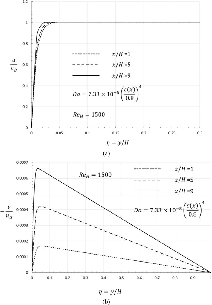
Figure 7a and b illustrate the axial development of the velocity field whose porosity varies following Eq. (61) with Da (x) evaluated from the power law (65) for the case of εref=0.8, dm/H=0.1,L/H=10,ReH=1500, and n = 1.5.
Figure 7.
Axial development of velocity field. (a) Streamwise velocity component and (b) normal velocity components.
The streamwise velocity profiles u/uB clearly indicate that the viscous boundary layer becomes “thinner” downstream, as both porosity and permeability decrease downstream. The corresponding normal velocity component −v/uB at the same locations are presented in Figure 7b. Figure 7a and b together suggest that some part of the fluid mass is shifted from the core toward the heated wall. This weak secondary flow results in a comparatively higher streamwise velocity layer near the wall, which is favorable in view of cooling the heated wall.
3.3 Boundary layer thickness and wall temperature variation
It is found that the wall temperature and Nusselt number variations are quite insensitive to the difference in the local Darcy number observed in the above two correlations. This may be attributed to the forgetfulness of the inlet conditions, which is inherent to the boundary layer theory. Therefore, only the results based on the Calmid correlation (59) are presented.
A series of calculations were conducted analytically and numerically for forced convective flows in a channel filled with a graded metal foam under equal solidity, for the cases of εref=0.8,dm/H=0.1,L/H=10, ReH=1500,Pr=0.7, and kfks=0.01. The exponent n for controlling the gradient of the porosity was set to 0, 0.5, 1.0, and 1.5, respectively. For given exponent n and other parameters, the velocity shape parameter ζx is evaluated using Eq. (39) to determine the velocity field. The local value of δf∗x=δf/H also can be found by using a standard shooting method once the ζx is locally determined, and then some other quantities of interest, such as the wall temperature, can readily be provided.
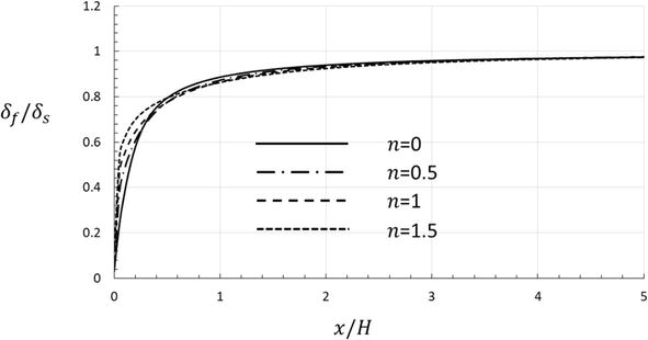
As illustrated in Figure 8, the thermal boundary layer thickness of the solid is always greater than that of the fluid phase due to the thermal conductivity of the solid phase is much greater. In fact, the thermal boundary layer of the fluid phase just started to grow at the inlet, namely δfx=0=0, while the boundary layer thickness of solid phase is non-zero as given by δs=6Biζ+2ζ+3ζ2+6ζ+11H. Therefore, the boundary layer thickness ratio δf/δs increases from zero at the inlet along downstream. Since δf/δs=1 is required for both fluid and solid temperature profiles to be identical, the L.T.E. assumption fails over a substantial distance from the inlet as can be seen from Figure 8.
Figure 8.
Axial development of thermal boundary layer thickness ratio.
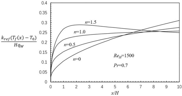
The effects of the exponent n on the wall temperature development are illustrated in Figure 9.
Figure 9.
Axial development of wall temperature.
A typical thermal boundary layer development can be observed in Figure 9 for the case of uniform porosity n = 0, that is, under the condition of constant heat flux on the wall, the wall temperature increases from the inlet in proportion to x13∼12, then to x far downstream, according to the classical boundary layer theory. The axial development of the wall temperature changes rather drastically depending on the value of n. When n is 0.5, the wall temperature near the inlet rises faster than the uniform porosity case, while the downstream wall temperature is suppressed. According to the correlation (61), the porosity for the case of n = 0.5 varies from 1 to 0.7 from the inlet to the exit based on the average porosity of 0.8, which changes in a moderate gradient but results in a remarkable temperature distribution variation over the axial distance. For the case of n = 1, the wall temperature was kept nearly at constant temperature of reasonably low level over most of the channel in axial direction of the channel. Thus, the results indicate that a uniform temperature can be achieved if the porosity is set to decrease linearly from the inlet to the outlet.
Furthermore, for the case of n = 1.5, the wall temperature steeply increases from the inlet and then decreases toward the exit after attaining its maximum value. The rather drastic increase in the effective thermal conductivity toward the exit explains the high sensitivity of the porosity gradient to the wall temperature distribution. Even a small increase in the metal volume fraction will result in a substantial increase in the effective thermal conductivity because the conductivity ratio of the metal to the fluid was set too large. Thus, the heat conducts away from the wall to the core region in the channel, keeping the wall temperature comparatively lower there.
3.4 Conclusions
In this section, the velocity profile and wall temperature development for the channel filled with axially graded metal foam were investigated analytically and numerically. The variation of the porosity follows power function of axial coordination with an exponent n based on an equal solid volume fraction. Velocity profiles for different cases were obtained based on the Brinkman-Forchheimer extended Darcy model. The solutions indicate that there exists a weak secondary flow toward the heated wall of the channel, enhancing cooling of the wall. It is found that the wall temperature is very sensitive to the axial gradient of the local porosity, even a moderate degree of the axial gradient with n = 0.5 changes the wall temperature distribution rather drastically. As a result, the wall temperature becomes almost uniform throughout the channel when n = 1.0, while, for n = 1.5, the wall temperature rises from the inlet, attains its maximum, and then decreases toward the exit. Thus, axially graded porous materials can be quite useful for designing effective cooling systems and controlling the desired working temperature and its uniformity.
4. Application of graded porous media in aeroengine cooling
The afterburner is an important component, especially in military aeroengine. It substantially improves the transient thrust of the aeroengine. However, the gas temperature at the afterburning state rises up to 2200 K, which is far higher than the temperature that the outer wall material can stand. Therefore, an efficient cooling system is definitely needed. The afterburner heat shield is often used to protect the outer wall from thermal load. However, the cooling area of the heat shield is large, film cooling holes are too many, but the coolant available for the cooling of the heat shield is relatively less. Therefore, the effective cooling of the heat shield is difficult, the high efficient cooling structure for the heat shield is definitely needed. However, due to the non-uniform pressure difference of the coolant and the mainstream, over the surface of the heat shield, the distribution of the coolant over the heat shield is also not uniform, which may lead to the thermal stress concentration on the heat shield itself. Therefore, the graded porous media may be adopted in the afterburner heat shield structure to improve its cooling effectiveness and temperature uniformity.
For convenience, in this section, four cases of impingement/effusion cooling structures embedded with uniform and non-uniform distribution pin fin array structures were considered as models to study the effects of graded structure on its heat transfer performance and cooling effectiveness. With several rib turbulator shapes, Rhee et al. [22] studied the motion and local heat/mass transfer parameters. They discovered that the location of the rib turbulators and the impingement/effusion holes affected the level of local heat/mass transfer, which was found to be boosted by the rib turbulators.
The cooling processes can be considerably impacted by lattice frame structures, which lead to higher levels of airflow disruption and an increase in the intensity of heat transfer within the flow channel thanks to the enlargement of the heat transfer surface area. Pins were shown by Funazaki [23] to be essential in improving the overall heat transfer of double-layer cooling. Li and Mongia [24] looked into how a double-walled cooling system affected heat transfer. Researchers suggested that for double wall cooling with a thin wall or thick wall, the addition of pins results in an increase of about 0.03 in overall cooling performance.
4.1 Calculation model
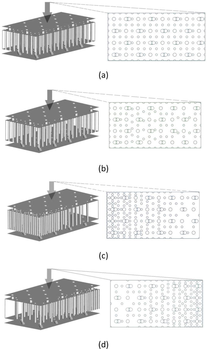
In this section, four cases of impingement/effusion cooling double-layer structures embedded with uniform or non-uniform (graded) distributed pin fin structures were treated as calculation models, as can be seen in Figure 10. Moreover, the relative location of impingement holes, effusion holes, and pin fins were also indicated.
Figure 10.
Calculation models: (a) case 1 (uniform distribution; 121 pins); (b) case 2 (almost uniform distribution; 96 pins); (c) case 3 (non-uniform distribution from highest density to lowest; 166 pins); (d) case 4 (non-uniform distribution from lowest density to highest; 166 pins).
It is significant to note that the shape of the hollow elements, as well as their diameter, remained constant. The location of the holes for both the upper and lower plates, as well as their diameters and angle of inclination, are also unchanged. Periodical boundary conditions are imposed on the side parts of the computational model. The CFD software was employed to create an unstructured mesh of the computational area, and a depiction of intricacy of the mesh is presented in Table 1.
Turbulence model
SST k-ω
Mesh type
Three-dimensional
Mesh form
Orthogonal
Table 1.
The main parameters of the simulation.
Table 1 shows the main parameters of the simulation, and Table 2 illustrates the number of grid cells for each model.
Name of a case
Number of cells
Case 1 (uniform distribution)
1,809,286
Case 2 (almost uniform distribution)
1,543,251
Case 3 (non-uniform distribution from highest density to lowest)
2,304,339
Case 4 (non-uniform distribution from lowest density to highest)
2,294,669
Table 2.
The number of cells for each case.
4.2 Flow structure and temperature distribution
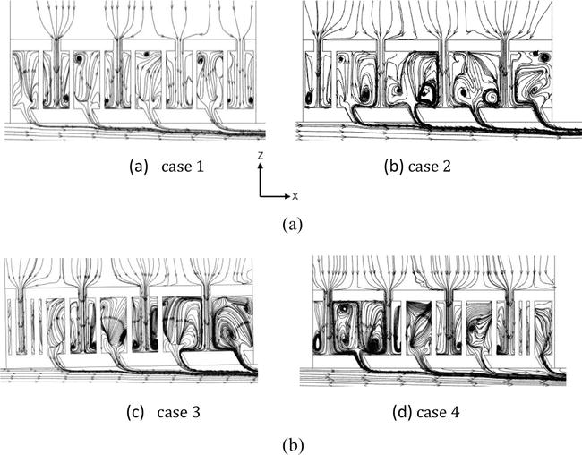
Figure 11a–d demonstrates the characteristic features of the flow structure for each model.
Figure 11.
Flow structures regarding the 4 cases with lattice frame elements of different distribution densities: (а) case 1, (b) case 2, (c) case 3 and (d) case 4.
In comparison to Figure 11a and b, it can be noticed that the most striking manifestations of vortices are revealed in the model whose structural elements are slightly deviated from a uniform distribution (Figure 11b). The difference between cases 3 and 4 (Figure 11c and d) is also noticeable. It is tangible that in the region of the lowest density of solid elements, the flow structure swirls throughout the volume of the occupied part of the space. However, otherwise, when the distribution density is high, there is a restriction of the free zone of flow propagation. In this case, good mixing of the flow is provided, which is accompanied by small vortex structures throughout the volume of the area that is occupied.
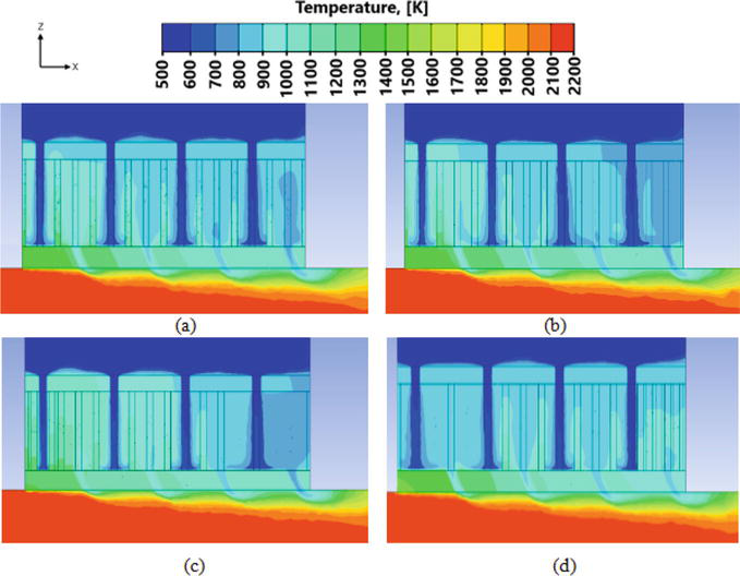
The evaluation of the flow behavior analysis is very necessary, as it affects further heat exchange processes. So, Figure 12 shows the temperature distributions for these 4 models.
Figure 12.
Temperature distribution regarding the different cases with different distribution densities of lattice elements: (a) case 1, (b) case 2, (c) case 3, and (d) case 4.
Going deeper into the analysis of the flow temperature inside the model in the interlayer space, it is noted that the part of the computational model where there is a high density of the distribution of elements of the lattice structure leads to a high intensity of heat exchange. This is due to the fact that with an increase in the distribution density, the interlayer space for mixing air flows decreases.
4.3 Overall cooling effectiveness
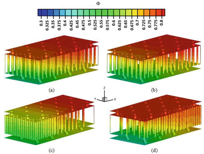
It is important to note that the overall cooling effectiveness is influenced by the interplay between different cooling mechanisms and their respective effectiveness values, and it is crucial to optimize the design and configuration of each cooling mechanism to achieve high overall cooling effectiveness. Figure 13 demonstrates the distribution of the overall cooling effectiveness on 3-D models. It is vital to note that the range of values ranges from 0.3 to 0.8 according to the indicator scale above with intervals of 0.325.
Figure 13.
3-D distribution of the overall cooling effectiveness for four models with different distribution densities of lattice elements: (a) case 1; (b) case 2; (c) case 3; (d) case 4.
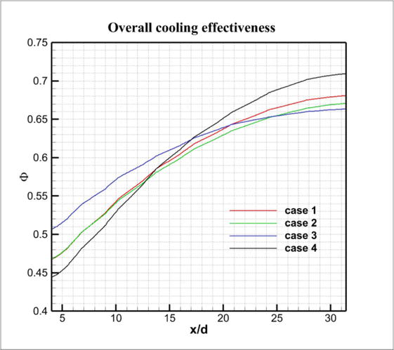
From the scientific point of view, it can be noticed that with a decrease in the number of pins, the intensification of heat exchange decreases, while an increase in the same elements is accompanied by an increase in heat exchange processes. That is, the density of the distribution of lattice elements is directly proportional to the overall cooling effectiveness. This is the conclusion that can be traced from Figure 14.
Figure 14.
The overall cooling effectiveness for four models with different distribution densities of lattice elements: red line—case 1; green line—case 2; blue line—case 3; black line—case 4.
However, to assess the overall cooling effectiveness, a graph was also constructed, presented in Figure 14. The blue line characterizes model 3, that is, the one whose intensification was maximal already in the first segment of the x/d ratio and whose overall cooling effectiveness is 0.515. It is revealed that the decrease in the pin distribution density is directly proportional to the decrease in the overall cooling effectiveness.
The worst initial data was shown by model 4 (black line), where there was minimum distribution density at the first stage (0.47). The overall cooling effectiveness across the entire model ∆Ф in this case was 12%. Nevertheless, the black line at its minimum value began to grow sharply and reached a maximum of 0.71, while the difference in overall cooling effectiveness was as much as 25%. Such an effective indicator was achieved thanks to a rise in pins in the model under study, which only provoked enhancement in heat exchange intensification.
Summing up, the best indicators were identified in the case 3. Also, it boils down to the fact that it is necessary to introduce such lattice frame structures in which the tendency of the distribution of pins from a constructive point of view will be accompanied by an increase in the density of their distribution.
4.4 Conclusions
The simulation work of the graded lattice structures with different arrangements of pins was numerically investigated using the appropriate software (CFD). Four different cases with various distributions of the ligament elements were assumed, as well as the characteristics of the mesh construction were presented. The evaluation information showed that additional indicators that improve heat transfer processes are directly affected by the distribution density. In addition, a decrease in the distribution density leads to a decline in the overall cooling effectiveness. It is proved that when designing a model with a high density of the distribution of elements at the initial stage, there is a sharp increase in the efficiency of heat exchange. Thus, functionally graded lattice structures can be used to achieve significantly high overall cooling effectiveness while at the same time having a high distribution density of lattice structure elements.
In this section, the flow and heat transfer in channels filled with vertical graded porous media and longitudinal graded porous media have been analytically investigated, respectively. The heat transfer characteristics and wall temperature variation principles for both cases have been presented. According to the analytical results, the vertical graded porous media in a channel enables to change the local velocity in the regions of near the wall or in the core, prompts the flow field in the low porosity region more distorted while accelerates the flow filed in the high porosity region. The highest heat transfer coefficient is obtained in the case of where the porosity decreases toward the heated wall, namely, more metal near the wall and less metal in the core region. For the case of a channel filled with axially graded porous foam structure, which follows a power function of axial distance with an exponent n, however, the velocity field is found that exist a weak secondary flow toward the heated wall, enhancing cooling of the wall. It is found that the exponent n controlling the axial gradient of the local porosity has a strong influence on the axial development of the wall temperature. A uniform wall temperature can be achieved in the case of n = 1.0, while a maximum temperature can be attained at the middle of the wall in the case of n = 1.5, instead of the fact that temperature keeps rising from the inlet to the end under the constant heat flux, which all the other researchers hold. The finding can be useful for designing effective cooling system, controlling the desired working temperature, and its uniformity.
On the other hand, the possibility of application of graded porous media in aeroengine cooling has been discussed. The numerical simulation work on the cooling of the afterburner heat shield with graded pin fin structures has been conducted. Four different cases of double-layer heat shields with various distributions of the ligament elements were constructed and examined their flow structure and cooling effectiveness. As a result, the decrease in the distribution density leads to decline in the overall cooling effectiveness, whereas a high density of pin fin elements arranged at the initial stage prompts the heat exchange and improves the overall cooling effectiveness upstream of the heat shield, although sacrifices part of that at the downstream, the gradient arrangement of pin fins improves the temperature uniformity over the surface of the heat shield. Thus, functionally graded lattice structures can be used to achieve significantly high overall cooling effectiveness while at the same time having a high distribution density of lattice structure elements.
The authors acknowledge gratefully the support from the National Science and Technology Major Project (J2019-III-0019-0063), the Innovation Capacity Support Plan in Shaanxi Province of China (Grant No.2023-CX-TD-19), the Grant of National Science Foundation of China (No.52006179), and the Fundamental Research Funds for the Central Universities (No.501XTCX2023146001).
Darcian velocity (apparent velocity) in x direction
u∗
dimensionless velocityu∗=u/−H2μdpdx
uB
bulk mean velocity
x
coordinate in the flow direction
y
coordinate normal to the channel wall
ε
porosity
ε∗
effective porosity
εB
bulk mean porosity
η
dimensionless vertical coordinate η=y/H
μ
viscosity
B
bulk mean
c
channel center-line
f
fluid phase, channel without a metal foam matrix
s
solid phase
w
wall
References
1.Kamiuto K, Yee SS. Heat transfer correlations for open-cellular porous materials. International Communication and Heat Mass Transfer. 2005;32:947-953
2.Dukhan N. Metal Foams: Fundamentals and Applications. Lancaster, Pennsylvania, USA: DEStech Punlications, Inc; 2013
3.Kaviany M. Laminar flow through a porous channel bounded by isothermal parallel plates. International Journal of Heat and Mass Transfer. 1985;28:841-858
4.Nakayama A, Koyama H, Kuwahara F. An analysis on forced convection in a channel filled with a Brinkman-Darcy porous medium: Exact and approximate solutions. Warme-und Stoffubertragung. 1988;23:291-295
5.Calmidi VV, Mahajan RL. Forced convection in high porosity metal foams. ASME Transactions on Journal of Heat Transfer. 2000;122:557-565
6.Koizumi M. FGM activities in Japan. Composites Part B: Engineering. 1997;28(1–2):1-4
7.El-Wazery MS, El-Desouky AR. A review on functionally graded ceramic-metal materials. Journal of Materials and Environmental Science. 2017;6(5):1369-1376
8.Wang B, Hong Y, Hou X, et al. Numerical configuration design and investigation of heat transfer enhancement in pipes filled with gradient porous materials. Energy Conversation and Management. 2015;105:206-215
9.Zheng ZJ, Li MJ, He YL. Optimization of porous insert configurations for heat transfer enhancement in tubes based on genetic algorithm and CFD. International Journal of Heat and Mass Transfer. 2015;87:376-379
10.Bai X, Kuwahara F, Mobedi M, Nakayama A. Forced convective heat transfer in a channel filled with a functionally graded metal foam matrix. Journal of Heat Transfer. 2018;140(11):111702
11.Iasiello M, Bianco N, Chiu WKS, Naso V. The effects of variable porosity and cell size on the thermal performance of functionally-graded foams. International Journal of Thermal Sciences. 2021;160:106696
12.Mauro GM, Iasiello M, Bianco N, Chiu WKS, Naso V. Mono- and multi-objective CFD optimization of graded foam-filled channels. Materials. 2022;15:968
13.Bai X, Zheng Z, Liu C, Nakayama A. Achievement of wall temperature uniformity by axially graded porous materials. International Journal of Heat and Mass Transfer. 2022;197:123335
14.Xu ZG, Zhao CY. Experimental study on pool boiling heat transfer in gradient metal foams. International Journal of Heat and Mass Transfer. 2015;85:824-829
15.Yang J, Yang L, Xu C, Du X. Numerical analysis on thermal behavior of solid-liquid phase change within copper foam with varying porosity. International Journal of Heat and Mass Transfer. 2015;84:1008-1018
16.Nakayama A, Kuwahara F, Kodama Y. An equation for thermal dispersion flux transport and its mathematical modelling for heat and fluid flow in a porous medium. Journal of Fluid Mechanics. 2006;563(25):81-96
17.Zhang W, Li W, Nakayama A. An analytical consideration of steady-state forced convection within a nanofluid-saturated metal foam. Journal of Fluid Mechanics. 2015;2015(769):590-620
18.Calmidi VV. Transport Phenomena in High Porosity Metal Foams. Denver, CO: University of Colorado; 1998
19.Amiri A, Vafai K. Analysis of dispersion effects and non-thermal equilibrium, non-Darcian, variable porosity incompressible flow through porous media. International Journal Heat and Mass Transfer. 1994;37:939-954
20.Yi Y, Bai X, Kuwahara F, Nakayama A. Analytical and numerical study on thermally developing forced convective flow in a channel filled with a highly porous medium under local thermal non-equilibrium. Transport in Porous Media. 2021;136:541-567
21.Wong P, Koplik J, Tomanic JP. Conductivity and permeability of rocks. Physical Review B. 1984;30:6606-6614
22.Rhee DH, Nam YW, Cho HH. Local heat/mass transfer with various rib arrangements in impingement/effusion cooling system with crossflow. Journal of Turbomachinery. 2004;126(4):615-626
23.Funazaki K, Tarukawa Y, Kudo T, Matsuno S, Imai R, Yamawaki S. Heat transfer characteristics of an integrated cooling configuration of ultra-high temperature turbine blades: Experimental and numerical investigations. ASME. Paper, GT2001-0148. 2001
24.Li S, Mongia H. An improved method for correlation of film cooling effectiveness of gas turbine combustor liners. In: 37th Joint Propulsion Conference and Exhibit, AIAA; July, 2001; Salt Lake City, Utah, USA. p. 3268
Written By
Xiaohui Bai, Cunliang Liu and Akira Nakayama
Submitted: 24 August 2023Reviewed: 02 September 2023Published: 21 December 2023