Open Access is an initiative that aims to make scientific research freely available to all. To date our community has made over 100 million downloads. It’s based on principles of collaboration, unobstructed discovery, and, most importantly, scientific progression. As PhD students, we found it difficult to access the research we needed, so we decided to create a new Open Access publisher that levels the playing field for scientists across the world. How? By making research easy to access, and puts the academic needs of the researchers before the business interests of publishers.
We are a community of more than 103,000 authors and editors from 3,291 institutions spanning 160 countries, including Nobel Prize winners and some of the world’s most-cited researchers. Publishing on IntechOpen allows authors to earn citations and find new collaborators, meaning more people see your work not only from your own field of study, but from other related fields too.
The computational fluid dynamics analysis is carried out to analyze the shock and flow characteristics of under- and over expanded supersonic free jets emanating from convergent-divergent nozzles. Influence of exit Mach number on shock cell lengths are analyzed with the help of density contours and schlieren images. A parameter based on an exit Mach number is obtained to characterize the pressure variation along the jet axis which shows them independent of the exit to ambient pressure ratio. Impingement flow fields over axisymmetric and wedge deflector are investigated employing numerically and compared with experimental results. Effects of jet expansion ratio and distance between the nozzle to deflector apex has been studied at various expansion ratios and distances. Impingement load is computed at various conditions. Pressure distributions over a surface of wedge and axisymmetric jet deflector are computed and compared between them. Pressure load on a diaphragm of a solid motor during lift-off of a satellite launch vehicle having four liquid engines is numerically simulated.
Noorul Islam Centre for Higher Education, Kumarcoil, Tamil Nadu, India
*Address all correspondence to: drrakhab.mehta@gmail.com
1. Introduction
The phenomenon of under- and overexpanded supersonic free jets emanating from a convergent-divergent nozzle and their impingement over a deflector are employed during the lift-off of a satellite launch vehicle. When a convergent-divergent nozzle deviates from its operating conditions then semi-periodic shock diamonds [1] and Prandtl-Meyer fans appear in the jet field. However, at the design conditions, the traditional smoothly contoured convergent-divergent nozzle with exit flow is a shock-free condition.
Mehta and Prasad [2] studied the effects of various exit Mach numbers and exit-to-ambient pressure ratios on shock-cell lengths with schlieren and density contour plots. The results showed that the Mach disk moves closer to the nozzle exit plane with decreasing pressure ratio, and the length of the first shock cell decreases. Three-dimensional Navier-Stokes equations [3] were solved to estimate the heat flux on a jet deflector caused due to impingement of the rocket exhaust of a canisterized missile. Based on the theory of computational fluid dynamics [4], the flow field of a rocket engine plume is simulated and analyzed by numerical method. Allgood and Ahuja [5] investigated the plume impact characteristics of ARES V propulsion system by numerical method, and the impact shape, surface pressure, temperature and other parameters of a flow deflector were obtained, which can help the practical construction of flow deflector and improve the safety and reliability of space launch.
Zhou et al. [6] have analyzed the four-engine liquid rocket flow field during the launching phase. Jiang et al. [7] presented an overview on progresses and perspectives of the jet impingement research for rocket launching.
Numerical simulations [8] have been performed to investigate the exhaust plume impinging on the wedge-shaped and cone-shaped deflectors. By comparative analysis between the four-engine rockets impinging jet on different deflector. Compared to the wedge-shaped deflector, the cone-shaped deflector could achieve better performance for deflecting with sufficient distance of the sidewalls. The flow fields of the four-engine rocket impinging on the flame deflector under different impingement and uplift angles are simulated. They observed that high temperatures on the deflector surface mainly occur on the impingement point or the cambered surface. A large impingement angle causes the reverse flow intensity to increase whilst a small angle causes the exhaust gas to deflect a little, a suitable uplift angle can smoothly guide the exhaust gas away from the deflector that the best thermal environment of the deflector channel appears at an impingement angle of 25°and an uplift angle of 5°. Numerical solutions of the impingement of an underexpanded axisymmetric supersonic jet on a flat plate at varied angles have been carried out by Wu et al. [9] and Kim et al. [10]. Experimental investigation of underexpanded supersonic jet impingement over inclined plate is carried out by Nakai et al. [11]. Computational analysis of underexpanded jets on inclined plate is carried out by McIlroy and Fujii [12]. Supersonic gas jets in conical convergent-divergent nozzles are studied numerically using the rhoOpenFOAM software solver [13].
The present study attempts to address flow field of supersonic free jets. Phenomena of jet expansion ratio, and distance between nozzle exit plane and deflector apex has been analyzed at various stand-off distance. Overall load coefficient has been obtained and compared with experimental data [14].
A conical convergent-divergent nozzle delivers over-expanded, fully expanded and underexpanded jet depending on the nozzle pressure ratio, ratio of stagnation pressure in the settling chamber to the ambient pressure.
2.2 Over expanded jets
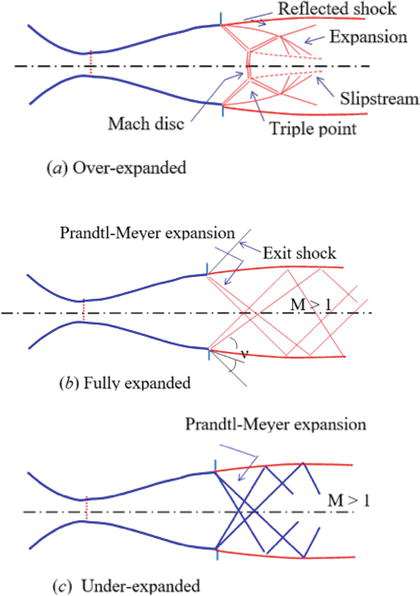
If the pressure in the ambient medium to which is discharging is greater than the nozzle exit pressure, the jet is said to be over expanded. Oblique shock waves are formed at the edge of the nozzle exit. These oblique shocks will be reflected as expansion waves from the boundary of the jet. Figure 1a schematically diagram delineates the waves in an over expanded jet. Due to this periodic shock cell structure is generated in the jet and the wave length of this periodic structure is found to increase with Mach number [15, 16].
Figure 1.
Schematic sketch of supersonic free jets (a) overexpanded, (b) fully expanded and (c) underexpanded.
Flow has passed through the shock waves will be turned the centre line and the oblique shock wave directed toward the centre line of the nozzle. This process of expansion and compression wave formation continues until the pressure of the jet field becomes the same as the ambient pressure and the flow becomes parallel to the nozzle centre line. These expansion and compression waves which intact with each other lead to the formation of diamond patterns termed shock cells.
2.3 Fully expanded jets
Figure 1b shows schematic sketch of fully expanded jet. The fully expanded flow occurs when ambient pressure is equal to exit pressure then the jet is also alternatively called as correctly expanded [17]. This jet is also wave dominated as an imperfectly expanded jet.
2.4 Under expanded jets
If the pressure in the ambient medium to which is discharging is less than the nozzle exit pressure, the jet is said to be under expanded as shown in Figure 1c. Since pa < pe a wedge-shaped expansion fans occur at the edge of the nozzle. These waves cross one another and are reflected from the opposite boundaries of the jet as compression waves. The compression waves again cross one another and are reflected on the boundaries of the jet as expansion waves. The gradual compression occurs Mach waves emanating at the wall, and the flow near the wall can be treated as isentropic. The flow properties changes gradually and isentropically and called Prandtl-Meyer angle can be written as
ν=γ+1γ−1tan−1γ+1γ−1M2−1−tan−1M2−1E1
The Prandtl-Meyer angle is the angle through which sonic flow turns to attain a supersonic local Mach number. When supersonic flow is turned through a convex corner, the flow expands, resulting in an increase in velocity and a drop in pressure. When a M1 expands to a M2, according to a Prandtl-Meyer expansion, the turning angle is ∆ν=ν1−ν2=±δ.
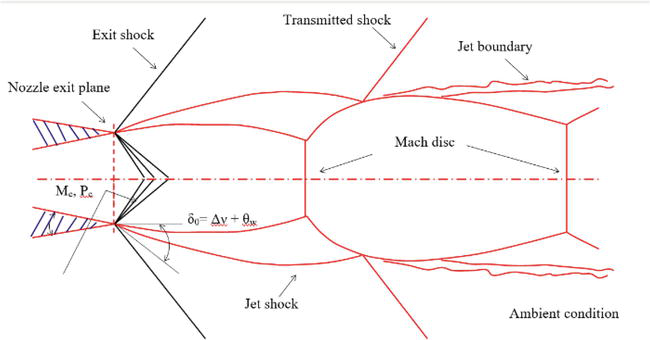
Supersonic jet emanating from a convergent-divergent nozzle may be overexpanded (pe/pa < 1), correctly expanded (pe/pa = 1) or underexpanded (pe/pa > 1) depending upon stagnation pressure P0. The basic flow field structures are delineated in Figure 2. Generally, it consists of repetitive shock cell, inviscid jet boundary and a shear layer. In the case of pe/pa = 1, the shock cells consist of weak shock and regular shock reflection. However, for imperfectly expanded jet (pe/pa ≠ 1) cases, formation of Mach disc takes place.
Figure 2.
Schematic sketch of flow field of overexpanded.
The location of Mach disk [2] moves away from the nozzle exit plane with increase in expansion pressure ratio pe/pa. For highly underexpanded case, the flow up to the Mach disc is generally calculated by different methods like method of characteristics. However, the flow downstream of Mach disc cells for viscous analysis. For pe/pa < 1 cases, the strong jet shocks from the nozzle forms the Mach disc very near to the nozzle exit; hence the estimation of Mach disc location becomes difficult.
The noise generated from the supersonic jet is dominated due to turbulent mixing in the shear layer for pe/pa = 1. However, for shock associated noise does become appreciable for jet pe/pa ≠ 1. For shock associated noise prediction, it is customary to obtain the shock cell lengths accurately Refs. [2].
During the lift-off condition of the multi-engine rocket, the exhaust jet from the rocket nozzle impinges on the launch pad and is produced complex impingement flow field. The pe/pa < 1 during the lift-off period. In order to estimate the impingement load on the jet deflector and for prediction of jet noise during the lift-off condition, it is necessary to obtain the free jet properties.
A numerical flow simulation is carried out to analysis supersonic free jets and jets deflector using turbulent, compressible Reynolds averaged Navier-Stokes equations. A two-equation turbulence model [18] with compressibility correction [19] is used to solve the governing fluid dynamics equations. A finite volume discretization is carried out in spatial coordinates to compute inviscid and viscous flux vectors. Time evolution is carried out by an explicit multistage Runge-Kutta method to achieve a steady state solution. The numerical algorithm is developed by taking into consideration structured grid arrangement. The numerical results are obtained for nozzle exit Mach number of 2.2, 2.6 and 3.1, exit to ambient pressure ratio of 0.6, 0.8, 1.0 and 1.2 and at different distance from nozzle exit to the apex of the axisymmetric and the double wedge deflector. The numerical scheme is computationally fast, easy to program and efficient. The centre line pressure distributions inside the free jets differs in the presence of the jet deflector. The numerical results are compared with the experimental data and are discussed in the next sections.
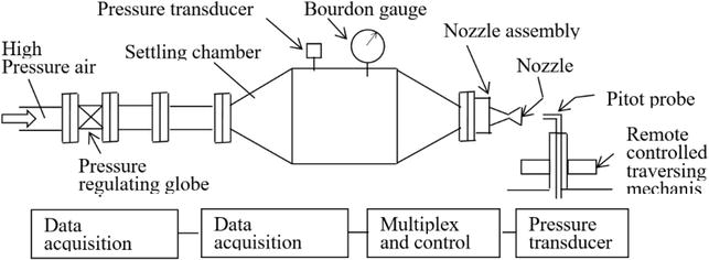
All the experimental simulations of supersonic free jet and jet deflector are conducted in an open jet facility as shown in Figure 3. High pressure dry air at 4.3 × 10⁶ Pa at ambient temperature is fed through a 15 × 10−3 m diameter pipe line to the settling chamber and nozzle assembly. A pressure regulating valve is used to control the operating pressure. The pressure in the settling chamber is continuously recorded and monitored using a Bourden pressure gauge and a pressure transducer. The experimental set up is coupled with data acquisition. The open jet facility can be operated continuously at the maximum pressure up to about 80 s.
Figure 3.
Schematic sketch of open jet facility.
The conical convergent-divergent nozzles are used for getting supersonic free jets. The nozzles are having semi-divergent angle of 15o. The dimensions of convergent-divergent nozzle and operating conditions are tabulated in Table 1. The nozzles A and B were operated at pe/pa < 1 and nozzle C is operated on pe/pa > 1. Pitot tube of 1.1 mm outer diameter is used for measuring the centre line pressure. The flow does not separate in the nozzle as per the criterion for 15o semi-conical angle of nozzle [14].
Nozzle
d*, mm
de, mm
Ae/A*
Me
Pressure ratio
A
2.18
30.0
2.005
2.2
0.36 < pe/pa < 1.90
B
9.2
15.72
2.923
2.6
0.39 < pe/pa < 1.62
C
10.66
23.0
4.657
3.1
0.47 < pe/pa < 0.88
Table 1.
Dimensions and operating condition of nozzles.
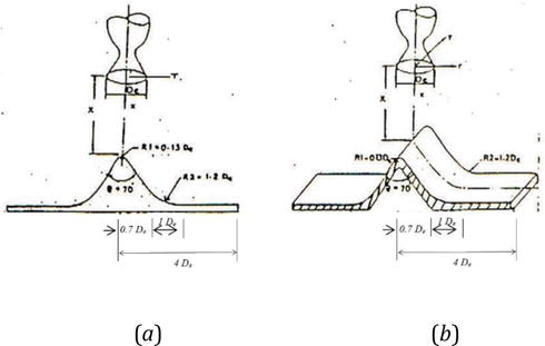
Axisymmetric and wedge deflector model consisted of 70o apex angle having tip bluntness of 0.13 De as shown in Figure 4, respectively. A curvature of radius 1.2 De is provided at a distance of 0.7 De from centre. The deflector surface becomes perpendicular to nozzle axis at 1.7 De. Both the deflector, that is, axisymmetric and wedge has the same apex angle, radius of curvature and base length. Static pressures on the deflector surface is measured employing scanivalve unit. A computer base data acquisition system is used for data analysis.
Figure 4.
Geometrical details of (a) axisymmetric and (b) wedge deflector.
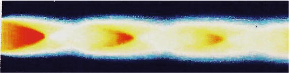
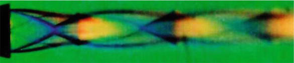
For the sake of brevity, we are displaying only density contour of Me = 2.6 and pe/pa = 0.8 in Figure 5. The characteristic features of supersonic free jets such as Mach disk, the intercepting and reflecting oblique shocks are well captured in the density contours. Figure 6 shows schlieren picture Me = 2.6 and pe/pa = 0.8 obtained from experiment [14].
Figure 5.
Density contour Me = 2.6 and pe/pa = 0.8.
Figure 6.
Schlieren picture Me = 2.6 and pe/pa = 0.8.
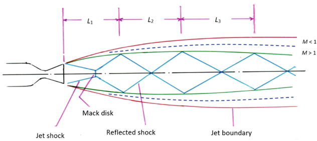
Figure 7.
Schematic sketch of a supersonic free jet.
A schematic sketch of based on the computed density contour and schlieren picture is illustrated in Figure 7. Mach disc location Lm, first, second and third shock cell length L1, L2, and L3, respectively are measured from schlieren pictures. All the discontinuities such as jet shock, triple point, slip line; reflected shock and shock cells are clearly visible as described in Figure 1. Mach disc location Lm compared with Love et al. [15], first, second and third hock cell length L1, L2, and L3, are compared with Abdel-Fattah [16].
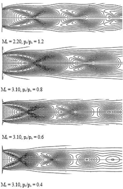
For the sake of brevity, we are presenting density contours in Figure 8 for Me = 2.2 and pe/pa = 1.2, Me = 3.1 and pe/pa = 1.2, 0.6 and 0.4. The characteristic features of supersonic free jets can be easily visualized in the density contours. The first Mach disk has a well defines triple point where the Mach disk, the intercepting and reflecting oblique shocks terminate. The slip line downstream of the Mach disk which separates the subsonic inner core of the jet from the surrounding supersonic flow is also visible.
Figure 8.
Density contour of supersonic free jets.
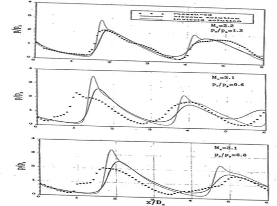
Figure 9 shows inviscid [2], present viscous and measured static pressure distribution [14] along the centre line of supersonic free jets Me = 2.2 and pe/pa = 1.2, Me = 3.1 and pe/pa = 0.6 and 0.8. The viscous results are observed to be in agreement with experimental data [14]. However, there is some discrepancy noticed at far-field which attributed to over prediction of the spreading rate of jets.
Figure 9.
Pressure distribution along the centre line of supersonic free jets.
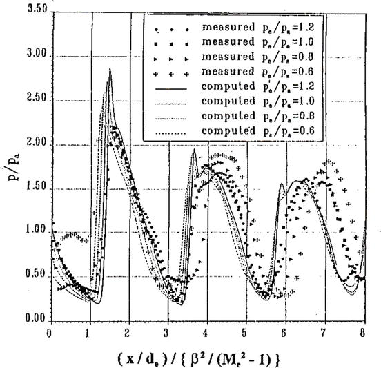
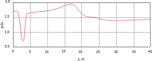
Figure 10 shows the variation of measured and computed pressure distribution along the jet axis for Me = 2.2 at pe/pa = 1.2, 1.0, 0.8 and 0.4 and compared with the measured static pressure. A non-dimensional parameter β2/Me2−1 is obtained to characterize the pressure variation along the jet axis independent of the exit to ambient pressure ratio pe/pa. The value of β2 = (Mj2–1) for pe/pa ≠ 1 supersonic jet are obtained using Tam and Tanna [20]:
Figure 10.
Pressure variation along the jet axis for Me = 2.2 at different pe/pa.
djde=MeMj1+12γ−1Mj21+12γ−1Me2γ+14γ−1E2
pepa=1+12γ−1Mj21+12γ−1Me2γγ−1E3
L1/d* varies linearly with β2 for pe/pa < 1 and shows good agreement with the result of Abdel-Fattah [16] and Mehta et al. [21]. A least square straight line fit from these data as.
L1/d∗=1.04β2–1.08forMe=2.21.03<β2<3.84
L1/d∗=1.15β2–1.95forMe=2.61.70<β2<5.81E4
L1/d∗=1.25β2–3.85forMe=3.13.08<β2<8.70
From the density contour measurement of L2 was carried out in the similar way as.
L2/d∗=0.87β2forMe=2.61.03<β2<3.84E5
The L2/d* varies linearly with β2 for all the nozzles irrespective of Me. in general, it is observed that L1 > L2 for pe/pa > 1 and L1 = L2 for pe/pa = 1 and L1 < L2 for pe/pa < 1. From the density contour is found about L3 = 0.94 L2. Table 2 shows the summary of shock cell length L1, L2 and L3 as a function of β2.
po/pa
pe/pa
β2
Mj2
L1/d*
L2/d*
L3/d*
Me = 2.2
12.88
1.2
4.36
5.36
2.15
5.5
8.8
10.69
1.0
2.84
4.84
1.75
4.7
7.7
8.55
0.8
3.23
4.23
1.4
3.0
6.5
6.47
0.6
2.50
3.50
1.0
2.9
5.0
Me = 2.6
23.95
1.2
6.38
7.38
2.6
6.65
10.95
19.95
1.0
5.76
6.76
2.2
5.8
9.5
15.55
0.8
5.03
6.03
1.76
4.95
8.1
11.97
0.6
4.16
5.16
1.35
3.9
7.1
Me = 3.1
19.12
0.8
7.70
8.7
2.2
6.2
10.1
25.59
0.6
6.62
7.62
1.75
5.0
8.3
17.09
0.4
5.70
6.24
1.2
3.6
6.18
Table 2
Summary of shock cells length.
5.2 Numerical analysis of jet deflector
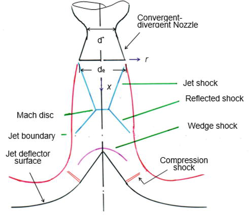
The impingement flow field in a jet deflector produced due to an over expanded supersonic jet is schematically illustrated in Figure 11. It can be observed from the diagram that the flow field consists of a jet shock, Mach disk, reflected shock, wedge shock and compression shock [22, 23]. The impingement flow field data are necessary for the design of the jet deflector.
Figure 11.
Schematic of the impingement jets over deflector.
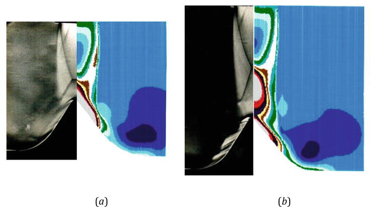
Mach density contours of the impinging jets have been shown over the axisymmetric deflector in Figure 12a and b for Me = 2.2 and Xc/De = 2.0 and Me = 2.2 and Xc/De = 3.0, respectively. It can be observed from the Mach contour that all the essential flow field features are well captured. Comparison between schlieren picture with Mach contour shows good agreement of flow field.
Figure 12.
Comparison of schlieren picture with Mach contour. (a) Me = 2.2 and Xc/De = 2.0 (b) Me = 2.2 and Xc/De = 3.0.
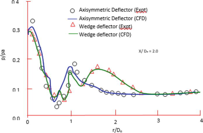
Figure 13 shows pressure distribution over the axisymmetric and the wedge deflectors for Me = 2.2, pe/pa = 1.2 and X/De = 2. The computed pressure distribution for axisymmetric case compares well with the experimental results. The comparisons of pressure variation over axisymmetric and wedge deflector placed at Xc/De = 2.0, indicate small differences in the apex region till r/De of 0.7. the maximum pressure occurs at large distance from the centre for wedge as compared to axisymmetric case.
Figure 13.
Pressure distribution over deflector for Me = 2.2, pe/pa = 1.2 and X/De = 2.
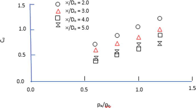
A quantity, which is of design interest is the overall impingement load, Ca = L/T. where T is thrust of the nozzle and L is integrated normal static pressure over the deflector. Load coefficient for various value of pe/pa and stand-off distance is shown in Figure 14. Ca increases with increase in jet pressure ratio at all distances X/De in the range of 2–5. However, at a fixed pe/pa the load coefficient decreased with increase in X/De. load coefficient for wedge deflector is found to be 40% higher than the axisymmetric case. The lower load coefficient for the axisymmetric case attributed to the pressure relief in the radial direction.
Figure 14.
Variation of load coefficient.
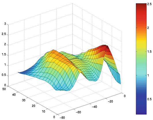
Pressure distribution over wedge deflector for Me = 2.2, pe/pa = 1.2 and X/De = 2 is shown in Figure 15. It can be observed from the pressure profile the influence of deflector surface. The pressure distribution is computed using three-dimensional inviscid flow solver.
Figure 15.
Pressure variation over wedge deflector for Me = 2.2, pe/pa = 1.2 and X/De = 2.
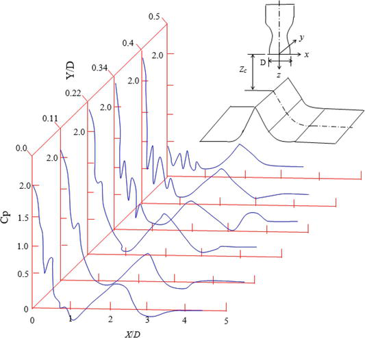
Figure 16 shows the pressure distribution over different section of the wedge deflector for for Me = 2.2, pe/pa = 1.2 and X/De = 2. There kinks are most likely to be due to the three dimensionality of the impingement flow field. However, the compression due to the curvature is still present. These surface pressure distributions were used to obtain overall impingement load coefficient. Integration has been done using the trapezoidal rule.
Figure 16.
Surface pressure distribution over wedge deflector.
During the lift-off condition of the rocket, the exhaust jet from the rocket nozzle impinges on the launch pad and is produced complex impingement flow field. The pe/pa is less than 1 during the lift-off period. In order to estimate the impingement load on the jet deflector and for prediction of jet noise during the lift-off condition, it is necessary to obtain the free jet properties.
A three-dimensional numerical simulation is carried using compressible Euler equations. The governing fluid dynamics equations are solved using finite volume method. Time integration is performed using an explicit multistage Runge-Kutta method.
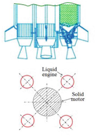
This problem is solved when the L-40 engine is operated during the lift-off time as shown in Figure 17. The boundary conditions are enforced by using the idea of image cells on the plane of symmetry. On the nozzle exit plane of L-40 engine, the following conditions are taken for the computational purposes:
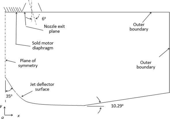
At the nozzle diaphragm of the core motor and solid wall of the jet deflector no normal flow conditions are applied. For quiescent external condition, the ambient pressure is imposed on the remaining sides of the computational domain (Figure 18).
Figure 18.
Computational domain.
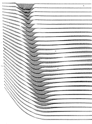
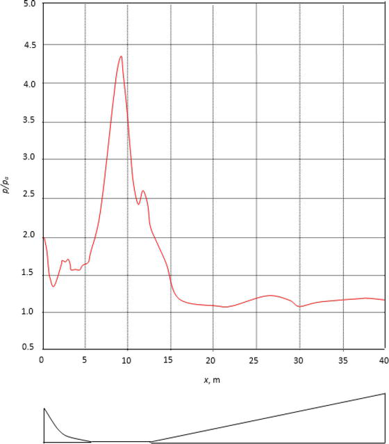
Figures 19 and 20 show the velocity field and density contour over the jet deflector. The velocity vector shows complicated flow field and also having recirculating zones. This can also be noticed in the density contour plot. Static pressure distribution along the deflector surface has been shown in Figure 21. A higher pressure is observed at a location downstream of the apex of the deflector which is impingement region of the jets. Figure 22 shows pressure on the base of the launch vehicle. It can be seen from the pressure distribution that the diaphragm is having pressure above the ambient pressure. It is important to mention that the present numerical analysis may predict higher conservative pressure distribution.
Figure 19.
Velocity field over the jet deflector at the lift-off.
Figure 20.
Density contour over the jet deflector at the lift-off.
Figure 21.
Surface pressure distribution along the jet deflector.
Figure 22.
Pressure distribution on the base of launch vehicle.
Numerical simulations are carried out to obtain supersonic free jets emanating from convergent-divergent nozzles at different exit Mach number and operating nozzle pressure ratio. Shock cells are obtained using density contours and a least square straight line is obtained from the numerical and experimental data. Effect of jet expansion ratio and distance between nozzle exit plane to deflector apex has been analyzed for various stand-off distance. Overall load coefficient has been calculated for the axisymmetric and wedge deflector. Pressure distributions on the jet deflector and on the base of rocket have been computed using Euler flow solver.
fully expanded jet Mach number corresponding to isentropic expansion of jet from P0 to pa
β2
(Mj2–1)
P0
stagnation pressure
pe
exit pressure
pa
ambient pressure
pt2
Pitot pressure along jet
Lm
Mach disc location
L1
First shock cell length
L2
Second shock cell length
L3
Third shock cell length
x
Axial distance from the nozzle exit plane
Xc
distance from nozzle exit plane to deflector apex
δ
deflection angle
γ
ratio of specific heats
ν
Prandtl–Meyer angle
References
1.Meyer T. Über zweidimensionale Bewegungsvorgänge in einem Gas, das mit Überschallgeschwindigkeit strömt. Göttingen: Georg-August Universität; 1908
2.Mehta RC, Prasad JK. Investigation of supersonic free jets emanating from convergent-divergent nozzles. International Journal of Computational Fluid Dynamics. 1998;10:81-71. DOI: 10.1080/10618569808961673
3.Basu S, Saha S, Chakraborty D. Numerical Simulation of Missile Jet Deflector. Journal of Spacecraft and Rockets. 2017;54:930-935. DOI: 10.2514/1.A33761
4.Ding J, Liu Y, He H. Numerical study on the effect of rocket plume to the jet flow deflector in liquid rocket engine test stage. Journal of Physics. 2019;1300:012052. DOI: 10.1088/1742-6596/1300/1/012052
5.Allgood D, Ahuja V. Computational plume modeling of conceptual ARES vehicle stage tests. 43rd AI-AA/ASME/SAE/ASEE Joint Propulsion Conference & Exhibit. Cincinnati, OH, USA: AIAA; 2007. p. 5708. DOI: 10.2514/6.2007-5708
6.Zhou Z, Zhao C, Lu C, Le G. Numerical studies on four-engine rocket exhaust plume impinging on flame deflectors with afterburning. Defense Technology. 2021;17:1207-1216
7.Jiang C, Han T, Gao Z, Lee C. A review of impinging jets during rocket launching. Progress in Aerospace Science. 2019;2019:109. DOI: doi.org/10.1016/j.paerosci.2019.05.007
8.Zhou Z, Zhang L, Le G. Numerical study for the flame deflector design of four-engine liquid rockets. Engineering Applications of Computational Fluid Mechanism. 2020;14:726-737. DOI: 10.1080/19942060.2020.1761453
9.Wu J, Lin T, Luke EA, Tong X, Cinnella P. Comprehensive numerical study of jet-flow impingement over flat plates. Journal of Spacecraft and Rockets. 2002;39:357-366. DOI: doi.org/10.2514/2.3834
10.Kim KH, Chang KS. Three-dimensional structure of a supersonic jet impingement on an inclined plate. Journal of Spacecraft and Rockets. 1984;31:778-782. DOI: doi.org/10.2514/3.26512
11.Nakai Y, Fujimatsu N, Fujii K. Experimental study of underexpanded supersonic jet impingement on an inclined flat plate. AIAA Journal. 2006;44:2691-2699. DOI: 10.2514/1.17514
12.McIlroy K, Fujii K. Computational analysis of supersonic underexpanded jets impinging on an inclined flat plate. AIAA Paper 2007-3859. 2007
13.Xiao L, Hao X, Lei D, Tiezhi S. Flow structure and parameter evaluation of conical convergent–divergent nozzle supersonic jet flows. Physics of Fluids. 2023;35:066109. DOI: 10.1063/5.0151556
14.Prasad JK. Experimental and Numerical Results of Free Jets and Impinging Jets. Chennai: IIT Madras; 1993
15.Love EB, Grigsby CE, Lee LF, Woodling MJ. Experimental and theoretical studies of axisymmetric free jets. Hampton, USA: NASA Langley Research Centre, TRR-6; 1959
16.Abdel-Fattah AM. Discrete tone emission from high-pressure ratio supersonic jets from convergent-divergent nozzles. AIAA Journal. 1988;26:283-291. DOI: doi.org/10.2514/3.9886
17.Rathakrishnan E. Gas Dynamics. 7th ed. Delhi, India: PHI Learning Pvt. Ltd.; 2020
18.Jones WF, Launder BE. The prediction of laminarization with a two-equation model of turbulent. International Journal of Heat and Mass Transfer. 1982;15:1-26
19.Sarkar S. The stabilizing effect of compressibility in turbulent shear flow. Journal of Fluid Mechanics. 1995;282:163-186. DOI: doi.org/10.1017/S0022112095000085
20.Tan CKW, Tanna HK: Shock associated noise of supersonic jets from convergent-divergent nozzles. Journal of Sound and Vibration 1982; 81: 337–358. https://doi.org/10.1016/0022-460X(82)90244-9
21.Mehta RC, Prasad JK. Estimation of shock cell structure of axisymmetric supersonic free jets. Indian Journal of Engineering & Materials Sciences. 1996;3:141-147
22.Lamont PJ, Hunt BL. The impingement of underexpanded axisymmetric jets on wedges. Journal of Fluid Mechanics. 1976;76:307-336. DOI: doi.org/10.1017/S0022112076000657
23.Prasad JK, Mehta RC, Sreekanth AK. Impingement of supersonic jets on an axisymmetric deflector. AIAA Journal. 1994;32:1535-1538. DOI: doi.org/10.2514/3.12225
Written By
Rakhab Mehta
Submitted: 12 June 2023Reviewed: 13 June 2023Published: 05 August 2023