 Open access peer-reviewed chapter
Abstract
CO2 flooding is one of the most promising EOR technologies. The laboratory experiments have gradually evolved from early basic experiments to the revelation of physicochemical mechanisms and multi-scale physical simulation studies. The numerical simulation method moves toward the novel numerical simulation coupling compositional simulation with geochemical reaction and the stress field. Moreover, the optimization method starts to focus on the multi-objective optimization of CO2 EOR and storage. Meanwhile, stratified gas injection processes and tools are crucial to implement balanced gas injection. The corrosion prevention technology is required to combine anti-corrosive materials and corrosion inhibitors. The injection-production adjustment is the priority to be considered in the early stage of gas injection. The chemical-assisted suppression methods, including foam agent, particles, and gel, are needed to implement in the later stage of gas injection. Gas channeling treatment with hierarchical management is crucial to tailor the different channeling channels. A full-chain optimization model based on net emission reduction and carbon footprint is suggested for the future system planning of CO2 EOR and storage. In general, the next-generation CO2 EOR technology not only aims to significantly increase the oil recovery but also achieves large-scale CO2 storage, providing strong support for carbon neutrality goals.
Keywords
- CO2 EOR and storage
- experiment
- numerical simulation
- multi-objective optimization
- chemical-assisted method
- full chain economic evaluation
1. Introduction
CO2 is a type of gas with high solubility in both oil and water. As crude oil is dissolved with a large amount of CO2, it will expand, with reduced viscosity and interfacial tension, forming a mixed-phase state with intermediate composition extracted. At the same time, the carbonic acid water formed by dissolving CO2 in water can also improve rock wettability, acidify rocks, and improve the oil-water mobility ratio. Owing to the high performance of oil displacement, the technology of CO2 flooding for enhanced oil recovery (CO2 EOR) has been widely used. The CO2 EOR process is typically operated in two ways: either water-alternating gas (WAG) or continuous CO2 injection. WAG flooding typically employs the use of a relatively large, initial slug of CO2 to mobilize residual oil. Figure 1 depicts the cross section of a typical WAG CO2 EOR operation [1]. Nevertheless, in continuous CO2 injection, the gas is injected continuously without water slugs for the distribution.
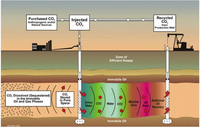
Figure 1.
Cross section of a typical WAG CO2-EOR operation. Source: Advanced Resources International.
As a predominant candidate for EOR application, CO2 has various advantages owing to its super-critical status at reservoir conditions. Significant viscosity reduction can be achieved as CO2 dissolves into crude oil. The higher the viscosity of crude oil, the greater the degree of viscosity reduction, and the higher the improvement in oil mobility. Meanwhile, the dissolution of CO2 induces volumetric expansion of crude oil and increases the formation energy. As CO2 gets in contact with fresh oil, mass transfer happens along with the dissolution, extracting a certain amount of light hydrocarbon components from the crude oil. Experimental results show that the components between C2 and C20 could be extracted completely as long as the pressure is sufficiently high, which reduces the interfacial tension significantly. Furthermore, the miscibility state could be achieved as the miscible zone is being formed. The miscible zone is closely related to the extraction and the condensation between CO2 and crude oil. Besides, the diffusion effect of CO2 in crude oil and brine is also one of the most important EOR mechanisms. The mineral dissolution is another impact as CO2-water reacts with carbonate minerals. In a word, the EOR mechanisms of CO2 flooding are remarkable [2, 3, 4].
CO2 EOR technology has been developed since the 1950s. The first patent for applying CO2 flooding in EOR was proposed in 1952. A lot of research on the CO2 EOR mechanism was performed later. In the 1970s, the first commercial CO2 EOR field application was carried out in the SACROC oilfield in the United States. In the 1980s, the industrialized application of CO2 EOR was promoted in the Permian Basin, forming a CO2 EOR-supporting technology system. Since the 1990s, attentions have been paid to the improvement on sweep efficiency of CO2 EOR. Research was conducted on well pattern matching and chemical agent for channeling suppression, resulting in the development of various technologies, such as CO2 vertical well injection with horizontal well extraction, and CO2 injection-assisted gravity drainage.
In 2010, the U.S. Department of Energy released a report outlooking the research directions of next-generation CO2 EOR technology. The two main research focuses are CO2 EOR and storage, and tight unconventional oil and gas development. The CO2 injection slug would be greatly increased to more than 0.8 ~ 1.0 HCPV. More attention will be paid to the matching of well pattern and well type, and chemical-assisted efficiency enhancement. The integrated optimization technology of CO2 EOR and storage is becoming increasingly important. In addition, the application of CO2 EOR technology has gradually shifted from conventional reservoirs to new fields such as tight unconventional reservoirs and residual oil resources. Meanwhile, the integration of CO2 EOR with hydraulic fracturing techniques is also taking place, which is becoming a new focus. By the end of 2020, the number of CO2 EOR projects has been increased to 142 in the U.S. The updated survey shows that incremental oil recovery from CO2 EOR in the U.S. was approximately 273,000 barrels per day (bpd) in 2020. Although it indicates a decline of about 9% from the 2019 survey (total of 299,000 bpd), CO2 EOR remains an attractive option for generating revenue as the 45Q tax incentive for anthropogenic CO2 is finalized [5, 6, 7, 8, 9].
As a technology chain, CO2 EOR is a systematic project, mainly including experiments, numerical simulation, reservoir engineering, injection and production technology, anti-channeling and sealing, economic evaluation, etc. These technologies will be described in detail below.
2. Experimental evaluation technology of CO2 EOR and storage
Experiments are the most direct way to study the mechanism of CO2 EOR. By introducing high-temperature and high-pressure conditions, we can realistically simulate the interaction process of CO2 with oil, water, and rock under reservoir conditions, therefore revealing the physicochemical nature of CO2 EOR.
The development of CO2 EOR experiments has gone through three main stages (Figure 2). The first stage is the basic evaluation experiment, including the PVT phase experiment, the long slim tube experiment, and the long core displacement experiment. The PVT phase experiment is to study the changes in reservoir fluid parameters before and after gas injection, which then provides basic parameters for reservoir numerical simulation study and reservoir engineering scheme. The long slim tube experiment is designed to determine the minimum miscible pressure between injected gas and crude oil, and thus to quickly evaluate the feasibility of gas flooding. The long core displacement experiment is a necessary means to simulate the effect of gas flooding under reservoir conditions, which helps to optimize the injection parameters and injection methods in the gas flooding process.
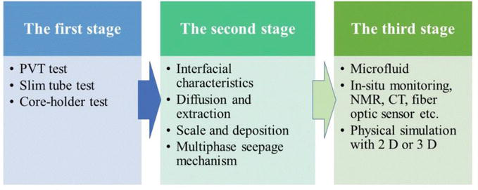
Figure 2.
The development history of experiments on CO2 EOR and storage.
The second is the mechanistic study stage, which reveals the physicochemical nature of the CO2 EOR process, such as the multiphase oil-gas-water interfacial characteristics, the diffusion and the extraction mechanisms, the solid phase deposition, and the multiphase seepage mechanism. The in-depth theoretical study of the mechanism provides a fundamental understanding of the technical process of CO2 EOR for researchers. Moreover, the CO2 storage mechanisms are new focuses. The dissolution of CO2 into brine induces the loss of the injected gas volume. The formation of carbonate water causes the mineral dissolution and sequestrates some parts of CO2 underground.
The third stage is the physical simulation stage. Multi-scale physical simulation with physical similarity is carried out to restore the conditions of CO2 flooding in the reservoir. This technology mainly presents the following characteristics: “small, precise, and large.” “Small” means the small pore-scale in the physical models. The physicochemical nature of nano-pore-scale conditions is gradually revealed, which provides theoretical support for the knowledge and understanding of the oil displacement mechanisms. “Precise” is achieved through the characteristics of automation, high resolution, in situ observation, etc. Accurate data can be obtained by characterizing the experimental process through in situ NMR or CT, new fiber optic sensors, automated robots, and other advanced means. “Large” means the physical similarity of the physical models by scaling up to reservoir conditions. At the same time, various new sensors have been integrated to enable real-time measurement of different field parameters during the displacement process and monitoring of gas flooding leading edge and saturation changes [10, 11, 12, 13].
To sum up, the experimental technologies of CO2 EOR have evolved from the initial determination of field-based parameters, through the interpretation of field problems, and restoration of production processes, to new digital experimental methods based on digital twins. In the future, CO2 EOR indoor experimental technology will develop toward more realistic and credible, more instructive, and more flexible and diverse. In addition, it gradually breaks through the original technical limitations, and changes from focusing on oil displacement to focusing on the sequestration effect, that is, focusing on the retention mechanism of CO2 itself in the reservoir. Experimental technology has also developed from formation physics to get integrated with geochemistry, petrophysics, mechanical engineering, information science, and other disciplines, forming a new multidisciplinary field.
3. Numerical simulation technology of CO2 EOR and storage
Numerical simulation is the basic means to study the engineering application of CO2 EOR. In 1953, Bruce G.H and Peaceman D.W simulated one-dimensional gas-phase unsteady radial and linear flows [14]. Later, it was extended to reservoir numerical simulation, that is, using a computer to solve the mathematical model of the reservoir, simulate the subsurface oil and water flow, provide the oil and water distribution at a certain time, and thus predict the reservoir dynamics.
3.1 Numerical simulation models
The current numerical models of CO2 EOR include five main types: CO2 EOR based on the black oil model, the transport-diffusion model, the pseudo-component model, the full-component model, and the novel component model.
The first model adopts the control equations of the black oil model and approximates the viscosity relationship with the mixing parameters, which can simulate various fingering phenomena and the effect of fingering on the areal sweep efficiency. The advantages of the model are simpler, less computational effort, higher stability, and better matching the actual miscible flooding process. The disadvantage is that it can only approximate the CO2 EOR process with poor accuracy. That is, it cannot fully reflect the transport-diffusion process and mechanisms.
In the transport-diffusion model, the fluid is divided into two components: oil and solvent. This model considers the strong diffusion effect, which makes it adaptable to the process of miscible flooding. However, the model does not adequately describe and modify the fluid properties, and cannot truly reflect the inter-phase and inter-component changes of the fluid in the CO2 flooding process. And, there is severe numerical dispersion when modeling the displacement leading edge.
The pseudo-component model, developed after the transport-diffusion model for component calculations, is similar to the pure-component model. The only difference is that the iteration of the equilibrium constant K is simplified. That is, the value of K is given a pressure-, temperature-, and component-dependent equation without participating in the iterative correction. The K value varies with the model parameters and requires a small computational effort, making the K value equation suitable for fast computation through experimental regression. The disadvantage is that the description of the components is not very accurate because the iterative solution of the fugacity equation and the gas-liquid equilibrium constants are not performed.
The full-component model can better simulate the mass transfer and component changes, including the simulation of gasification, condensation, expansion, and other processes. The disadvantage is that the processes of CO2 EOR and the multi-staged CO2 extraction of crude oil are not well considered. At the same time, correction of parameters such as fluid density and viscosity is not incorporated.
The novel component model of CO2 EOR has the advantages of both the component model and the black oil model, which can improve the calculation speed based on the simulation of mass transfer and component changes. By involving various practical conditions, it can simulate the solubility of CO2, the compressibility of rocks and fluids, the heterogeneity and anisotropy of the formation, the gravity effect of fluids, and the correction of fluid density, viscosity, solubility, and relative permeability, etc. [15, 16, 17, 18, 19, 20].
3.2 Synchronous simulation of CO2 EOR and storage
With the increasing importance of CO2 emission reduction, the effectiveness of CO2 sequestration has gradually attracted attention. The consideration of storage mechanisms in the CO2 EOR process is the latest research direction in the development of component numerical simulation technology. At present, the Eclipse and CMG numerical simulation software is commonly used to perform the phase calculation of CO2 in both oil and gas phases by flash calculation. However, for the conditions where CO2, oil, water, and gas co-exist, the dissolution of CO2 in formation water cannot be considered in the models. In addition, for the latest sequestration models or simulators, the geochemical reaction process is considered, while the effects of porosity and permeability parameters caused by geochemical reactions are not readily available. Due to the computationally intensive nature of the module considering the geochemical reaction, it is not possible to synchronize its operation with the oil displacement module, and it can hardly achieve the integration of CO2 EOR and storage. Synchronous simulation of CO2 EOR and storage requires simultaneous consideration of CO2 dissolution in both oil and water phases, chemical reactions between carbonate, water, and reservoir minerals, and other storage mechanisms. The commonly adopted approach is to address the effect of CO2-water reaction with rock minerals on reservoir porosity/permeability parameters through an equivalence treatment. As shown in Figure 3, by invoking the equations of porosity/permeability changing with carbonated water injection acquired in the laboratory, the program is figured out and used to automatically analyze the calculation results. The results are further used to calculate the effect of the reservoir mineralization reaction on the porosity and permeability of each grid during that simulation time period. Then, Eclipse is restarted to calculate the next time period. The cycle is repeated until the whole calculation is completed. In addition, the partitioning effect of CO2 in oil and water is mainly considered by the interpolation of CO2 solubility tables. That is, the equilibrium process of CO2 in oil and gas phases is still calculated through the flash equation, while the equilibrium process of CO2 in water is calculated using the gas-water solubility table interpolation. Besides, the capillary hysteresis is considered by introducing the parameter of relative permeability hysteresis effect on the basis of fitting experimental data. The above method enables the equivalent consideration of the sequestration mechanism in the CO2 EOR process, thus achieving simultaneous numerical simulation of CO2 EOR and storage processes [21].
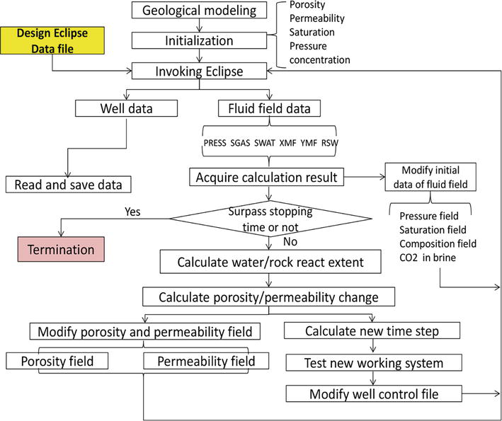
Figure 3.
Numerical simulation flow diagram for CO2 EOR and storage.
4. Optimization design method for CO2 EOR and storage
Optimization design for CO2 EOR and storage is a key step in engineering practice, which has evolved from the initial dimensionless curve method, to the streamlined simulation evaluation, the single objective optimization, and the current multi-objective optimization and system decision-making. Originally, only the oil displacement process was optimized. Later, the optimization method developed into the integrated CO2 EOR and storage optimization, which provides technical means for large-scale CO2 storage during the process of oil displacement.
4.1 Water/gas flooding characteristic curves
The early dimensionless curve method was used to predict engineering implementation according to the empirical method before the advent of computers. The production parameter characterization was carried out according to the water flooding characteristic curve, which provides a basis for decision-making in the prediction of production parameters. The so-called water flooding characteristic curve is a relationship between cumulative oil production, cumulative water production, and accumulation of fluid production during water injection. These curves have been widely used for water injection development of dynamic and recoverable reserves forecasts. Based on actual oilfield production data, water flooding characteristic curves are used to predict field production data and recovered reserves in a statistical way. Owing to the intuitive data and easy calculations, this method is commonly used by field reservoir engineers. Currently, there are 10 types of water flooding characteristic curves. The most commonly used ones are type A, type B, type C, and type D. These characteristic curves are the relationship initially proposed by former Soviet Union scientists through statistics on actual production data and laboratory data aiming to characterize water flooding performance. Later on, the curves were extended by researchers and derived into new expressions, which were named after the researchers. In 1978, Tong Xianzhang named the Maksimov water flooding characteristic curve as type A curve. The three other water flooding characteristic curves were named as type B, type C, and type D curves sequentially by Chinese researchers [22, 23, 24, 25].
However, no standard gas flooding characteristic curve has been developed for CO2 EOR. The main challenge is the complicated relative permeability characteristics of the three phases: oil, gas, and water. Due to the intense physical and chemical interaction process among CO2, oil, and brine, the physical parameters of the fluids take on the dynamic change, especially for crude oil and CO2. Moreover, the flow mechanism becomes more complex, which makes it difficult to describe the process in the theory of water flooding characteristic curve. However, the segmented log-log correlations between the cumulative gas production and the cumulative oil production have been established through theoretical derivation, forming a method to describe the characteristic curve of gas flooding in the process of CO2 immiscible displacement in low-permeability reservoirs (Figure 4). Combining with indoor experiments and field tests, the empirical formula has been verified. It shows that the cumulative gas production and cumulative oil production present a segmented double-logarithmic linear variation relationship, which clarifies the rationality of the characteristic curve of gas flooding [26]. The responding performance of gas flooding could be predicted based on the gas flooding characteristic curve described above. The gas breakthrough point could be determined exactly. The incremental oil recovery could be also calculated theoretically.
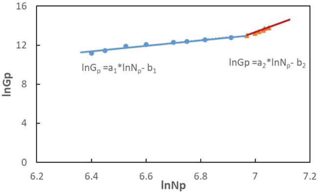
Figure 4.
Gas flooding characteristic curve for CO2 immiscible flooding.
4.2 Synchronous optimization of CO2 EOR and storage
With the development of numerical simulation, the optimization design of reservoir engineering has gradually shifted to multi-parameter from single-objective optimization. For CO2 EOR, the optimization design of various injection and production parameters by the incremental recovery factor or oil exchange ratio provides the optimal objective for reservoir engineering plan development. However, for CO2 EOR and storage, there are two objects to be optimized. Since there are differences or even contradictions in the design concepts between conventional CO2 EOR and CO2 storage technologies, it is crucial to find commonalities between the two and form an integrated optimization technique for both CO2 EOR and CO2 storage. For CO2 EOR, the gas source comes from natural gas or industrial gas. The injection method is continuous injection or WAG injection during secondary or tertiary oil recovery. The common injection volume is about 0.25 ~ 0.30 HCPV. The optimization goal is the optimal recovery factor, which requires injecting as little CO2 as possible to produce more oil. For CO2 storage, however, the gas source is limited to industrial gas. The timing of injection takes place early or after the reservoir is abandoned. The injection volume is often very large, typically in the range of 1.0 to 1.5 HCPV, which requires the injection of as much CO2 as possible to produce the most oil and water. The optimization target is a high storage ratio. In the project of integrated CO2 EOR and storage, it is necessary to use parameters that can describe both the oil recovery factor and the CO2 storage ratio and evaluate the project comprehensively. Therefore, in order to adapt to different decision scenarios and engineering objectives, a comprehensive evaluation function of the integrated oil displacement-embedded effect is introduced and used as the evaluation criterion to study the optimal injection and recovery plan under different scenarios [15, 27, 28].
where
In the process of synchronous optimization of CO2 EOR and storage, the importance of CO2 EOR and CO2 storage under different scenarios is characterized by adjusting the ratio of ω1, ω2. A reasonable selection of weights is very important for the optimization process. If the primary objective is to improve the recovery of crude oil, ω1 can be taken as 1. If the primary objective is to maximize the storage of CO2, ω2 can be set as 1. There is no unified evaluation criterion for CO2 storage in China as the legal and taxation policies for CO2 storage are unknown. As shown in Figure 5, during the full life cycle of CO2 EOR and storage projects, oil recovery is often the main focus at the beginning. Once the displacement effect reaches its limit and the gas-to-oil ratio (GOR) increases significantly, the CO2 EOR and the CO2 storage are both important. At the later production stage when there is almost no continuous crude oil production, more attention is paid to the storage amount. In the optimization study of CO2 EOR and storage, there is only one optimal objective and a set of parameters to be optimized at each stage, so the best-optimized parameter values can be determined by the extreme or inflection points of the simulation results [21].
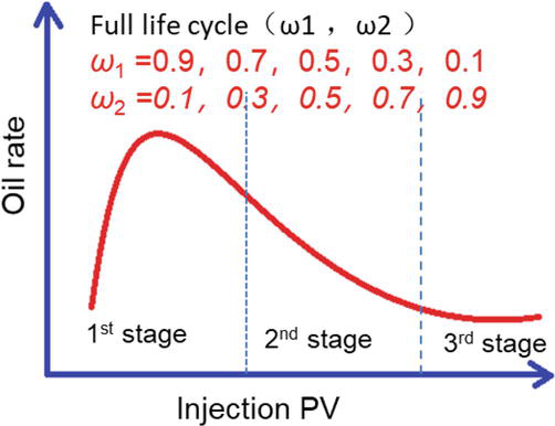
Figure 5.
Global optimization method for CO2 EOR and storage.
5. Supporting engineering technologies of CO2 EOR and storage
The injection and production engineering is the key component of CO2 EOR technology, which plays an important role in carrying forward and downward. It is the guarantee for completing the development targets proposed in the reservoir development plan, as well as the basis and starting point for the construction of surface engineering. Researchers have done a lot of work on CO2 injection, oil production, and anti-corrosion technologies, with impressive achievements, which greatly promote the development of this technology [29, 30, 31, 32, 33, 34].
5.1 CO2 injection technology
5.1.1 Blanket gas injection technology
At present, the blanket gas injection technology is more commonly used in CO2 EOR field tests. For reservoirs with a relatively uniform suction profile, the blanket gas injection works well for an effective displacement of multiple oil reservoirs. The traditional injection string adopts an integral string design, which exposes various problems: poor sealing effect of the packer, fast rise of casing pressure, short oil-casing pressure balance time, etc. In addition, the formation may be damaged by the necessary well operation, such as bleeding, and well-killing. The operation under pressure is expensive as well. To avoid these problems, the no-kill gas injection pipe column with a split-body releasing tool is proposed, which works with the functions of anchoring, backwashing, split-body releasing tool, and operation without killing the well. The corresponding string-supporting tools are also incorporated.
5.1.2 Stratified gas injection technology
For multi-layered reservoirs with large differences between layers, gas channeling and flow control problems caused by the viscosity difference between CO2 and crude oil and the strong heterogeneity are key issues in the development process of CO2 injection. Gas channeling will cause the injected CO2 to form an ineffective cycle, which greatly reduces the CO2 sweep volume and the oil recovery factor. Meanwhile, the CO2 will cause serious corrosion problems after gas channeling. Compared to blanket gas injection, stratified gas injection is more helpful in achieving uniform reservoir utilization and avoiding gas channeling caused by reservoir heterogeneity.
Commonly used stratified gas injection technologies include single-tube and concentric double-tube stratified gas injection. For the single-tube stratified injection technology, a packer is used to separate the injection layers. Each injection layer corresponds to a distributor, which can be opened and closed to achieve the alternating injection between different layers. The downhole stratified injection volume is controlled by adjusting the dispenser nozzle. In fact, the CO2 EOR single-tube stratified gas injection technology involves several problems. First, the downhole stratified gas injection tools and process design require further optimization. The size of the injection nozzle is small, which can be easily blocked due to asphaltene precipitation in the injection well. In addition, measurement of CO2 at a supercritical state is difficult, and the stratified gas injection measurement and testing are challenging due to complicated nozzle flow characteristics. Moreover, the CO2 injection pressure is high, leading to high safety risks during the test.
For the concentric dual-tube stratified gas injection technology, the upper oil layer is injected through the outer and central tubing annulus, and the lower oil layer is injected through the central tubing. Limited by the size of the casing in the old wells, the tubing may be blocked during gas injection in concentric dual-tube. Besides, well operation in dual-tube is difficult and expensive. Currently, the stratified gas injection technology is still in the R&D and testing stage, which requires further research and improvement.
5.1.3 Gas injection equipment
Considering gas injection sealing, corrosion prevention, and operational requirements, stainless steel injection wellheads and airtight tubing strings for gas injection are utilized. Different types of injection tubing strings are developed, including no-kill well injection tubing strings, mechanically anchored injection tubing strings, and self-balancing injection tubing strings. These tubing strings have a maintenance-free period of more than 27 months. For the purpose of balanced gas injection, the CO2 eccentric injection tubing string and the support compensation self-balancing injection tubing string are designed and developed to achieve CO2 stratified gas injection.
For the problems of serious corrosion and increasing GOR in the production wells with ordinary carbon steel wellheads and 3Cr or 13Cr stainless steel downhole tools, inserted oil recovery tubing strings and multi-functional oil recovery tubing strings are developed. The pumping efficiency of oil recovery pumps is improved by employing measures such as an anti-corrosion pump + high-efficiency gas anchor, spiral flow sieve tube + anti-gas pump, over-bridge pump + long tail pipe, which helps to extend the maintenance-free period of oil wells as well. In addition, the production efficiency is also improved by the combination of various other measures. A combined capillary tube pressure measuring device and corrosion tube piece are used to monitor the real-time gas flooding efficiency and corrosion state. A corrosion inhibitor is added to the annulus to protect the casing. Production control valves are added to allow operation without well-killing.
5.1.4 Gas injection station for different gas supply
In general, different injection technologies have been developed according to the characteristics of the CO2 feed source. A pressurized injection station is employed for gas injection in the case of large-scale and continuous gas supply. This injection station incorporates the booster unit that boosts, heats, and distributes to the dispenser room, and the injection unit from the dispenser room to the single well. An integrated dual-media distribution process with alternative gas and water injection is established. The liquid CO2 pump injection technology is developed with self-pressurized CO2 storage tanks. For discontinuous gas supply, a convenient and flexible skid-mounted injection method is adopted, which integrates an injection system, automatic control system, and heating system, to meet the injection needs of different geological conditions, scales, and pressures.
5.2 Oil production technology
Oil production technology in China mainly relies on conventional oil pumps. As the field test progresses, the oil production wells face the problems of elevated casing pressure, elevated GOR, and intermittent gas production, which seriously affect the pumping efficiency and production of the wells. As the CO2 EOR test is performed in fields with low permeability and low production, gas-liquid separation is difficult. Conventional lifting methods used in wells with large GORs have poor pumping liquid filling, low pumping efficiency, and an “air lock” problem. This makes the pump unable to work normally and unable to maintain the CO2 EOR effectiveness. At the same time, “liquid surface shock” may occur, which accelerates the damage to the downhole equipment, such as the pumping rod, valve stem, valve cover, pump valve, oil pipe.
5.2.1 Elevated casing pressure
For the issue of rising casing pressure, gas energy in the casing can be utilized to help the rod pump lift the fluid. Combining the rod pump and gas lift oil production techniques, a gas lift valve is installed at a certain depth of the well to help the rod pump lift the fluid. During the pumping process, when the annular casing pressure rises above the opening pressure of the gas lift valve, the gas enters the tubing through the gas lift valve to reduce the density of the fluid in the tubing and hence lift the fluid. When the annular casing pressure is lower than the opening pressure of the gas lift valve, the gas lift valve closes. By installing the gas lift valve, the CO2 gas energy of the breakthrough can be effectively used, and the casing pressure can be automatically controlled within a lower range so that the system is maintained at a dynamic equilibrium state.
5.2.2 Elevated GOR
For the issue of high GOR, we can increase the inlet pump pressure by controlling the bottom hole pressure, meanwhile installing a gas-liquid separator under the pump. When the produced fluid enters the wellbore, the gas flows upward due to gravity, and the liquid flows downward into the tubing string to achieve preliminary separation. When the liquid enters the gas-liquid separator after gravity separation, it is in fact a mixture of oil-liquid-gas-sand. The mixture enters from the lower inlet and travels down along the spiral surface. The denser sand particles travel along the outside of the spiral under the centrifugal force and enter the tail pipe of sedimentation. The gas and liquid travel down along the inside and enter the inner pipe from the bottom, and then enter the spiral gas-liquid separator, where the liquid travels upward along the outer spiral and gets discharged through the drainage sieve tube, entering the oil pump sieve tube. The gas goes up along the inner surface into the gas collection hood and gets discharged by the exhaust valve, entering the casing-tubing annulus. When the gas affects the lift due to increasing gas-liquid ratio, the use of gas anchors and anti-gas pumps can be considered to achieve a better lifting effect. The anti-gas oil pump provides a channel for the gas in the pump by setting a hollow pipe. This increases the liquid filling factor in the working cylinder, reduces the GOR in the pump, eliminates the interference of gas, prevents gas lock, and effectively improves the pumping efficiency.
5.2.3 Produced gas recovery
In addition, for the problem of gas reinjection during the CO2 EOR process, there are mainly three different produced gas recovery technologies. The first is the CO2 flooding gas recovery and separation technology applicable to large-scale, low-to-medium CO2 content distillation coupled with low-temperature fractionation. This technique generally adopts chemical absorption decarbonization technology. The second is the low-temperature fractionation decarbonization technology applicable to large-scale, high CO2 content cases. The third one is suitable for small-scale skid-mounted produced gas reinjection systems with a CO2 capture rate greater than 80% and purity greater than 95%. In addition, the following three methods can be applied for the treatment of produced gas: direct reinjection, CO2 dilution reinjection, and rectification-distillation reinjection. If the light hydrocarbon content in the produced gas is high, the rectification-distillation recovery technique can be used. After the light hydrocarbon recovery, the remaining gas can be directly reinjected. If the CO2 content in the produced gas is low, it can be reinjected by mixing with pure CO2 to increase the CO2 concentration. If the CO2 content is high, it can be reinjected directly [35, 36, 37].
5.3 Anti-corrosion technology
Although dry CO2 gas is not corrosive, serious corrosion of carbon steel can be caused when CO2 is dissolved in water. Typical features of CO2 corrosion include local pitting, moss-like, and table-top corrosion, which often cause accidents such as tubular perforation, fracture, gas leakage, and wellhead damage, thus affecting normal production. Since most of the CO2-flooded gas injection wells and oil production wells are old wells, the wellbore was designed and completed as a conventional oil well, where carbon steel combined with J55, N80, and P110, was used for the casing, which is seriously corroded. According to the site anti-corrosion requirements, an indoor high-temperature and high-pressure reactor was used to simulate the site CO2-containing environment, and the effects of the tubing, CO2 partial pressure, temperature, flow rate, solution mineralization, pH value, and other factors on corrosion were analyzed and evaluated. The results show that the corrosion rate of 13Cr material is low, basically about 0.01 mm/a, while the corrosion rate of common carbon steel material is as high as 5–7 mm/a. Therefore, anti-corrosion measures must be taken. Considering the characteristics of injection and production processes in the CO2 test area, the following measures can be taken to prevent or delay the corrosion of CO2 on the tubular: optimizing the tubing string structure, utilizing corrosion-resistant materials, and injecting corrosion inhibitors.
5.3.1 Tubing string structure optimization
For injection wells, the annulus above the packer can be filled with oil-based annulus protection fluid to eliminate stress corrosion environment and avoid corrosion of carbon steel casing and tubing. When implementing water-gas alternation in injection wells, to prevent contact between CO2 and water, gas injection wells must be filled with a corrosion inhibitor plug before water-gas alternation. For production wells, based on the characteristics of the oil production process, combined with research results of corrosion and protection technology, corrosion-resistant materials and corrosion inhibitors can be employed locally to prevent or delay the tubular corrosion. CC-grade anti-corrosion wellheads and coated or liner tubing are used for the production. Pumping rods, pumps, plungers, vanes, ball seats, and other components need to resist CO2 corrosion as well. For wells without packers, a corrosion inhibitor is added from the casing-tubing annulus. For wells with packers, a corrosion inhibitor is added in the annulus above the packer. If the downhole tools are made of corrosion-resistant materials and the tubing is coated or lined, protection of the annular casing also requires the addition of corrosion inhibitors. Corrosion test pegs or rings are installed at representative locations to regularly monitor the corrosion of the tubing in the well and to optimize the corrosion protection program.
5.3.2 Corrosion-resistant alloy
According to the current development of related technology in China, the anti-corrosion technologies can be divided into two aspects: anti-corrosion-technology-controlled and corrosion-resistant-alloy-controlled. The anti-corrosion technology includes corrosion inhibitor anti-corrosion, and coating anti-corrosion, which can be selected according to the actual situation in the region. Among all the common anti-corrosion measures, internal coating corrosion and cathodic protection corrosion are limited in use as the application conditions are relatively harsh. The measures of ordinary carbon steel with corrosion inhibitors and corrosion-resistant alloys are used more frequently. Although the initial investment for using corrosion-resistant alloy is higher than other measures, the corrosion protection performance is better. The ordinary carbon steel assisted with corrosion inhibitor costs less initially, while the later operation process is more complex, which leads to higher capital investment. Particularly for the wells with high temperature and high pressure, corrosion-resistant alloy works much better than the normal carbon steel.
5.3.3 Corrosion inhibitor
In projects where CO2 injection time is relatively short, ordinary carbon steel with corrosion inhibitor is more practical for corrosion protection. During the corrosion inhibitor injection, the formulations of the corrosion inhibitor are critical. It developed from the initial imidazoline-type CO2 corrosion inhibitor into an agent system that integrated scale inhibition, sterilization, and corrosion prevention, which can effectively inhibit SRB bacterial corrosion and scaling. When applied in the field, it is also necessary to carry out corrosion inhibitor formulation evaluation in combination with the reservoir conditions in the test area to determine the optimal corrosion inhibitor formulation. At the same time, corrosion inhibitor dosing concentration, dosing method, and dosing cycle are the main factors affecting the corrosion protection effect. At present, the research on the mechanism of CO2 corrosion is getting in-depth, and the corrosion protection measures have achieved certain progress. The key problem is how to take the simplest, most effective, and most economical anti-corrosion measures considering the complex factors affecting the site.
5.3.4 Cathodic protection
As the partial pressure of CO2 rises, the amount of CO2 dissolved in water rises and the pH of the aqueous solution decreases, which greatly increases the possibility of the cathodic depolarization process of hydrogen, thus causing the corrosion to intensify. Therefore, cathodic protection can also help in corrosion protection. However, the operation process of cathodic protection is complex, the construction program is susceptible to the site environment. This makes the implementation of cathodic protection expensive and the application is thus limited. Coating anti-corrosion treatment is another common anti-corrosion measure. As the coating is performed at ultra-high temperature, the quality of the equipment can be improved, so that it is not affected by CO2 corrosion. However, the application of coating at the wire buckle is challenging, which makes it not applicable to the cases under loading.
The integrity of the wellbore plays an important role in the implementation of CO2 EOR technology, for both oil displacement and CO2 storage processes. Anticorrosion technology is critical to wellbore integrity to ensure proper implementation of the CO2 EOR process and to establish a solid foundation for long-term safe storage of CO2.
6. Research on gas channeling suppression system and technology of CO2 EOR
So far, various methods have been applied to prevent CO2 gas channeling, including mechanical plugging, injection and production parameter adjustment, WAG injection, and chemical-assisted methods. By using mechanical plugging, injection rate control, and WAG, we can improve the CO2 distribution in the injected well section and increase the vertical sweeping of injected CO2. However, it is only effective to adjust conformance in the vicinity of the wellbore but not for formations far away from the injection well. When CO2 passes through the perforation holes, the flow is controlled only by the reservoir heterogeneity and the flow mechanisms such as channel and gravity overburden. By injecting water and CO2 alternatively, we can enhance both microscopic oil displacement efficiency and macroscopic sweep efficiency of CO2 injection. This can prevent viscous fingering and delay the early gas breakthrough.
Chemical-assisted CO2 EOR mobility control or gas channeling suppression technology is one of the main development directions of the next-generation CO2 EOR technology identified by the U.S. Department of Energy. CO2 EOR mobility control and sealing methods mainly involve the injection of organic or inorganic chemical agents to increase CO2 viscosity or reduce effective permeability, thus reducing the mobility ratio and improving the oil displacement effect. First, CO2 thickening agents are used to thicken CO2 by adding polymer compounds such as siloxane polymers, fluoropolymers, and polymethacrylates to the injected gas. It can generally increase CO2 viscosity by 20–30 times. The disadvantages are the low solubility of polymer compounds in CO2 and the high cost. In addition, an inorganic gel system is another way to control CO2 mobility. The reaction between CO2 and silicate is used to form inorganic silicate gels. The advantage of this method is its lower cost, while the disadvantage is that the time of gel formation is difficult to control.
In the technique of organic ammonia salt profile control, CO2 is used to react with organic amines to form a salt containing crystalline water to plug the formation. Commonly used amines include monoethanolamine (MEA), diethanolamine (DEA), triethanolamine (TEA), N-methyldiethanolamine (MDEA), 2-amino-2-methyl-1-propanol (AMP), etc. Among other small-molecule organic amines, ethylenediamine (H2NCH2 CH2NH2) has the lowest price. With good injectability, it can selectively seal the channels of CO2 gas channeling. Moreover, an organic gel sealing system is the main way to manage water and gas channeling. By adding cross-linking agents, the intermolecular cross-linking of polymers is established, forming a net-like structure of the gel system. Currently, several gels are used in combination, such as Cr3+ crosslinking, aluminum crosslinking, phenolic crosslinking. This type of gel system has poor applicability in reservoirs with high temperature and high salinity, low permeability, etc. The use of acrylamide copolymers with temperature-resistant and salt-resistant structural units and large molecules of multifunctional group cross-linkers to generate gels is in the research and development stage.
The most frequently studied and applied CO2 mobility control is the foam system, which has good selective plugging ability for the formation with prominent inter- and intra-layer conflicts and large differences in oil saturation. It is characterized by low strength and short validity. At present, nanoparticle-stabilized and polymer-enhanced foam are hot spots of research concern. Some indoor and field studies on CO2 foam injection methods have been carried out in different countries. For example, CO2 foam field tests have been conducted in Rock Creek Oilfield, Virginia, and North Ward Estes Oilfield, Texas in the United States. In China, CO2 foam flooding field tests have been conducted in Yumen, Karamay, Daqing, and Jidong oilfields. However, the stability of foam in the CO2 foam injection method is affected by multiple factors such as pressure, temperature, residual oil saturation, and salts in formation water. There is no in-depth research on CO2 foam flooding technology. The supporting technology of CO2 foam injection is not ready in place, and the injection mechanism is not clear. This greatly increases the risk of CO2 foam flooding.
It is difficult to have a long-lasting effect for gas channeling with the traditional plugging method. This is probably the main reason for not using traditional plugging in large-scale CO2 flooding sealing applications. The chemical sealing technology for CO2 flooding in China has just started. There are few reports of large-scale application in oilfields. As the research progresses, the future direction of CO2 mobility control and sealing method is graded management and composite synergy, that is, to achieve effective sealing of CO2 through the combination of multiple methods [38, 39, 40].
Gas channeling during the CO2 EOR process cannot be avoided. However, by chemically assisted plugging, most of the injected CO2 is retained in the subsurface, which can effectively expand the CO2 sweep efficiency and improve the CO2 EOR effect. In general, gas channeling requires hierarchical management (Figure 6). For high-permeability zones, a nano-modified stable foam system should be used for flow control, with a plugging rate of over 90%. For medium- and small-scale fractures, an organic-inorganic composite gel system can be used for chemical plugging, with a plugging rate of over 95%. For large-scale fractures, conventional methods are hardly effective. Adaptive gel particles can be used for bridging and plugging. By implementing hierarchical management through various methods, the extent of gas channeling can be effectively alleviated, and the gas displacement efficiency can be improved. At the same time, the CO2 storage ratio can be greatly increased. Therefore, CO2 channeling suppression is a technical guarantee for large-scale CO2 storage in the process of oil displacement.
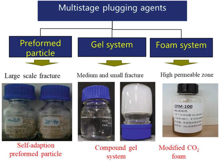
Figure 6.
CO2 chemical enhancement system.
7. Full-chain optimized economic evaluation technology for CO2 EOR and storage
7.1 Challenges for economic evaluation
As carbon capture, utilization, and storage (CCUS) technology is a cluster of many technologies, it is not only complex in terms of variety, technology classification, and cross-sectoral complexity, but also dynamic in terms of planning and development. Moreover, the economics of CCUS projects are significantly influenced by various factors such as international and domestic climate change policies and changes in international energy prices. These complex factors bring a great challenge for the large-scale deployment and application of this technology. In addition, it is difficult for the traditional deterministic economic evaluation methods to effectively plan for CCUS technologies under complex and uncertain conditions. For example, the different stages of CO2 injection technology and the diversity of different injection methods can lead to uncertainty in CO2 source requirements.
Traditional deterministic planning methods are difficult to respond and solve complex uncertainty problems effectively. With the continuous development of CCUS technology, a cross-regional storage utilization network from gas source to stored CO2 will be formed. However, in the process of planning large-scale CCUS projects carried out across regions, the gas source supply at the gas gathering stations has a dynamic nature. Under the uncertain conditions of dynamic demand for different storage utilization methods (e.g., EOR utilization, saline formation storage utilization), CO2 supply scheduling planning is required. Decision makers formulating the CO2 allocation policy for each storage area based on the experiences will largely increase the risk of CO2 oversupply or undersupply. In this complex uncertain environment, the CO2 supply allocation scheduling planning is difficult to be managed effectively using traditional deterministic planning methods. Further coupling of uncertain optimization methods is required to develop effective models for rational planning of CCUS.
7.2 Different economic models
Scholars have proposed a variety of CCUS system optimization models to explore ways to reduce costs and investment decision risks. At present, the main economic models include the economic evaluation model for each CCUS link, the economic evaluation model for CCUS based on subsidies and incentives, the CCUS planning model based on uncertain optimization methods, and the planning model for CO2 supply distribution scheduling.
7.2.1 Evaluation model for each CCUS link
The economic evaluation models for each link mainly focus on optimization analysis of CO2 reduction cost, energy efficiency, and energy demand for pre-combustion, post-combustion, and oxygen-enriched combustion capture methods in coal-fired power plants. For the transportation and pipeline, the impact of different transportation methods on the cost and the impact of compression and energy consumption in the pipeline process are discussed. In terms of storage, the economic analysis is mainly focused on the CO2 EOR and storage processes. The integrated costs of produced CO2 recovery, compression, reinjection, and oil displacement are mainly considered. A full-chain economic evaluation method for CO2 EOR and storage process is developed.
7.2.2 Evaluation model based on subsidies and incentives
The economic evaluation model of CCUS based on subsidies and incentives mainly considers incentives such as carbon taxes or fiscal subsidies to evaluate the economics of CCUS. Due to the high initial cost of CCUS technology, the funding problem cannot be solved by relying solely on corporate financing. External financing channels for CCUS technologies include market-based economic incentives and government financing incentives. As an important economic incentive for CCUS technology to reduce emissions, carbon trading has attracted much attention globally because of its flexible market mechanism. Domestic and international scholars have developed economic evaluation models for CCUS projects and analyzed the impact of carbon trading and incentive policies on CCUS investment decisions. In the past, many scholars have carried out economic evaluations for CCUS projects through external economic incentive policies, such as carbon trading prices. However, there is a lack of systematic studies considering the whole process of carbon capture, transportation, storage utilization, recycling, and reinjection. Consideration of the resource benefits and environmental benefits of large-scale GHG emission reduction resulting from the utilization of CCUS technology is missing as well. Therefore, it is difficult for the past studies to effectively evaluate CCUS technology and conduct CCUS full process planning studies with consideration of resource and environmental benefits [41, 42, 43, 44, 45].
7.2.3 CCUS planning model based on uncertain optimization methods
The CCUS planning model based on uncertainty optimization methods is designed to effectively solve the uncertainty problem in the CCUS planning and management process. Various uncertainty optimization methods have been developed, while the most widely used ones are three mathematical programming methods: interval programming, fuzzy programming, and stochastic programming. The interval programming method can effectively reflect the uncertainty information based on interval form in the engineering and technology planning process, which can provide a relatively stable solution for decision-makers. This method has been widely used in various fields such as energy planning, power, and atmosphere. The fuzzy mathematical programming method mainly introduces fuzzy sets into the mathematical programming method to deal with complex fuzzy uncertainty problems. This method is mainly applied to deal with fuzzy uncertainty problems of CCUS or to carry out the evaluation of a technical aspect of CCUS. Stochastic programming methods can effectively reflect the stochastic uncertainty of CCUS. The common stochastic programming methods include two-stage programming, multi-stage programming, chance-constrained programming, and stochastic robust programming. Few researchers have applied this method to the full process planning of CCUS. It was more frequently used to conduct planning research for a technical link of CCUS technology [46, 47].
7.2.4 Scheduling planning model for CO2 supply distribution
The scheduling planning model based on CO2 supply and allocation is mainly used to solve the issue of future network construction from gas source to storage utilization across regions. Researchers have carried out the development of CCUS transport optimization and scheduling planning models and achieved large-scale effective deployment of CCUS. For example, based on mixed-integer, multi-stage CO2 transport and storage, a network model called the CCTS model was used to optimize the deployment of CO2 capture, flow, and injection volumes. For saline aquifer storage and CO2 flooding, a CO2 pipeline network dynamic optimization allocation model is constructed and applied to optimize the whole project, mainly for selecting the most suitable CO2 storage sites. In addition, there is also a pipeline network model based on source-sink matching optimization, which involves multiple sources and sinks. Optimal supply allocation is achieved from different emission sources such as power plants, cement plants, oil refineries, oilfields, coal beds, and saline aquifer storage.
7.3 Full-chain optimization model
Researchers have conducted a series of studies on CCUS technology from different perspectives. Their studies on strategic planning and techno-economic analysis of CCUS are relatively macro or one-sided, which can hardly guide the planning and techno-economic analysis at the project level. The development and application of CCUS-related models are more focused on a certain technology and process optimization. For example, the existing CCUS system planning models focus on two aspects: source-sink matching and pipe network optimization. The existing research lacks the lowest cost system optimization of the whole process project from the perspective of the system, according to the interaction between various technical links within the system. Particularly, the whole process system optimization research combined with CO2 flooding oil utilization is missing. The current model is not a full-chain optimization model, that is, capture-compression-transport-injection-oil displacement (or gas displacement, coalbed methane, etc.)-recycle injection-long-term storage monitoring, etc. Particularly, the cost of cycle injection and monitoring are less considered. Therefore, it is difficult to reflect the lowest cost of the full-process CCUS-EOR project and the respective programming scheme based on the lowest cost. Due to the lack of support from relevant full-process system models, the past studies on the economics of CCUS based on carbon trading and government policy support can hardly provide a solid decision-making foundation. Some of the models do not evaluate the possible net regional emissions. As each link of CCUS consumes a certain amount of energy, which is equivalent to emitting a certain amount of CO2, the net reduction of the whole region should be the amount of CO2 stored minus the emissions of each link. Therefore, the future CCUS system planning model should be a full-chain optimization model based on net emission reduction and carbon footprint. In addition, the existing studies have failed to reflect the dynamic nature of CCUS project planning, uncertainty, and technical and commercial risks.
8. Conclusions
Generally, the development of CO2 EOR technology mainly focused on two directions: improving the oil displacement effect and increasing the storage ratio. For improving the oil displacement effect, lots of studies were conducted on increasing the oil displacement efficiency and expanding the sweeping effect. By injecting water or gas in advance to replenish the formation energy, the formation pressure was raised above the minimum miscible pressure, thus achieving miscible flooding, and significantly increasing the oil displacement efficiency. In addition, the sweep efficiency of gas flooding can be effectively increased by improving the well pattern, matching different well types, and using appropriate reservoir modification measures. When injection and production parameters or process control measures fail to work, chemically assisted efficiency enhancement methods need to be considered. The addition of specific chemical agents can effectively reduce the minimum miscible pressure, block the gas channel, and increase the sweep efficiency, thus improving the gas flooding effect. To obtain an overall improvement of the field oil displacement effect, abundant indoor experimental studies are conducted. Based on the experimental results, corresponding numerical simulation methods are formed, and reasonable reservoir engineering and field implementation plans are designed. Generally, it is easier and less costly to implement by adjusting the injection and production parameters. On the contrary, it is less economical by injecting chemical agents, with high dosages of chemicals and high costs, probably leading to environmental problems as well, which conflicts with the environmental protection concept of CO2 storage.
For improving the sequestration effect, the research is mainly focused on the scientific problem of how to increase the retention rate of CO2 in the formation. This issue can be addressed by learning from the idea of flood management. First, taking the idea of “plugging,” the gas channels are blocked in the production wells, allowing the gas to move to other parts of the formation, and thus achieving underground CO2 retention. In addition, taking the idea of “unblocking,” the produced gas is recovered and reinjected into the formation to achieve system-wide CO2 retention. Currently, the latter idea is more commonly used in the field. That is, CO2 is recycled by recovering from the produced gas and injecting it back into the formation. It can reduce the amount of newly purchased CO2 and lower the cost of oil recovery. Meanwhile, the CO2 retention rate is increased and the sequestration effect is improved as well.
Furthermore, the next generation of CO2 EOR technology would focus on two aspects of the integrated CO2 EOR and storage, the application of CO2 EOR in unconventional resources. The CO2 injection amount is more than 0.8–1.0 HCPV. The chemical-assisted method is more important. Additionally, the well pattern is more flexible. The storage coupling CO2 EOR is required to be considered. The application of CO2 EOR in tight oil, shale oil, and ROZ become the focus. The integrated CO2 EOR and fracturing would be crucial in the development of these resources.
CO2 EOR and storage are developing toward a direction that integrates enhanced oil recovery factor and CO2 sequestration effect. As a complex process that incorporates gas injection, oil production, CO2 storage, anti-corrosion technologies, planning, optimization, and implementation of CO2 EOR and storage are challenging. The current experimental study of CO2 EOR has been more concentrated on the physiochemical mechanisms, such as the interaction among CO2, crude oil, brine, and rock. To be more realistic and flexible, the larger-scale experiments, such as microfluidic and physical simulation, are attracting more attention. For numerical simulation, the methods integrating the flow process with geochemical reaction and the variation of the stress field are preferred. Meanwhile, both CO2 flooding and the sequestration mechanism should be equivalently considered in the simulation. The optimization design method has developed from the initial statistical method, through single objective optimization, to the current multi-objective optimization, which optimizes both oil displacement and CO2 storage. As key components of CO2 EOR and storage technology, the supporting engineering technologies are discussed in detail, including gas injection, oil production, and anti-corrosion technologies. Particularly, the anti-corrosion technology is critical to the wellbore integrity and proper implementation of the CO2 flooding process. Gas channeling is another main problem to be prevented during the implementation of CO2 EOR and storage. Here, the gas channeling suppression technologies are summarized, including mechanical plugging, injection and production parameter adjustment, WAG injection, and chemical-assisted methods. With chemically assisted plugging, most of the injected CO2 is retained in the subsurface, greatly increasing the CO2 storage ratio. Therefore, CO2 channeling suppression is a technical guarantee for large-scale CO2 storage in the process of oil displacement. Although various studies on economic evaluation models for CCUS projects have been carried out in the past, it is challenging to integrally consider the whole process system optimization due to the inherent complexity and dynamic nature of planning and development of the CCUS process. Therefore, a full-chain optimization model based on net emission reduction and carbon footprint is suggested for the future system planning of CO2 EOR and storage.
Acknowledgments
Thanks to the CCUS team of SINOPEC E&P Research Institute. Support for the National Key Research and Development program 2022YE0115800 and 2016YFB0600805-1. Support was provided by the National Science and Technology Major Project of the Ministry of Science and Technology of China 2016ZX05048003. The authors also show their deepest gratitude to Dr. Li Yang, the academician of China Engineering Academy.
Abbreviations
2-amino-2-methyl-1-propanol | |
carbon capture, utilization and storage | |
carbon dioxide | |
computerized tomography | |
diethanolamine | |
enhanced oil recovery | |
gas oil ratio | |
hydrocarbon pore volume | |
organic amines, ethylenediamine | |
N-methyldiethanolamine | |
monoethanolamine | |
nuclear magnetic resonance | |
pressure-volume-temperature | |
triethanolamine | |
water alternative gas injection |
References
- 1.
U.S. Department of Energy/National Energy Technology Laboratory, Improving Domestic Energy Security and Lowering CO2 Emissions with “Next Generation” CO2-Enhanced Oil Recovery (CO2-EOR), DOE/NETL-2011/1504, prepared by Advanced Resources International, 2011. Available from: http://netl.doe.gov/energyanalyses/refshelf/PubDetails.aspx?Action=View&Source=Main&PubId=391 - 2.
Jarrel PM et al. Practical Aspects of CO2 Flooding—Monograph Volume 22, Society of Petroleum Engineers, Richardson, Texas, 1st Printing; 2002. ISBN 1-55563-096-0 - 3.
Haynes S Jr, Alston RB. Study of the mechanisms of carbon dioxide flooding and applications to more efficient EOR projects. In: SPE/DOE Enhanced Oil Recovery Symposium. Tulsa, Oklahoma; 1990, SPE 20190-MS - 4.
Martin DF, Tabor JJ. Carbon dioxide flooding. Journal of Petroleum Technology. 1992:396-400 - 5.
Koperna G, Wallace M, Reid T, et al. A Survey of U.S. CO2 Enhanced Oil Recovery Projects; 2021 - 6.
CO2 Enhanced Oil Recovery—Executive Summary. Institute for 21st Century Energy. USA; 2012 - 7.
Rui W, Zengmin L, Chengyuan L, et al. Research status and development trends of worldwide new technologies for enhanced oil recovery. Petroleum Geology and Recovery Efficiency. 2021; 28 (5):81-86 - 8.
Remson D. Storing CO2 and Producing Domestic Crude Oil with Next Generation CO2-EOR Technology[R]. National Energy Technology Laboratory; 2010 - 9.
Wallace M. The U.S. CO2 Enhanced Oil Recovery Survey[R]. Advanced Resources International Inc.; 2021 - 10.
Ghedan S. Global laboratory experience of CO2-EOR flooding. In: Paper SPE 125581 Prepared for Presentation at the 2009 SPE/EAGE Reservoir Characterization and Simulation Conference Held in Adu Dhabi, UAE. 2009 - 11.
Yellig WF, Metcalfe RS. Determination and prediction of CO2 minimum miscibility pressure. JPT. 1980:160-168 - 12.
Mansour EM, Al-Sabagh AM, Desouky SM, et al. A laboratory investigation of carbon dioxide-enhanced oil recovery by focusing on CO2-oil physical properties. Egyptian Journal of Petroleum. 2019; 28 :21-26 - 13.
Zekri AY et al. Experimental investigations of variations in petrophysical rock properties due to carbon dioxide flooding in oil heterogeneous low permeability carbonate reservoirs. Journal of Petroleum Exploration and Production Technology. 2013 - 14.
Bruce GH, Peaceman DW, Rachford HH, et al. Calculations of unsteady-state gas flow through porous media. Journal of Petroleum Technology. 1953; 5 (03):79-92 - 15.
Lee KS, Cho J, Lee JH. Numerical modeling of CO2 EOR. In: CO2 Storage Coupled with Enhanced Oil Recovery. Cham: Springer; 2020. DOI: 10.1007/978-3-030-41901-1_3 - 16.
Abass AE, Gawish AA, Elakhal EM. Simulation study of different modes of miscible carbon dioxide flooding. Egyptian Journal of Petroleum. 2018; 27 (4):1195-1207 - 17.
Yuan D, Wu Y, Binshan J, et al. A practical compositional method for simulation of CO2 flooding in porous and fractured petroleum reservoirs. In: Presentation at the SPE Asia Pacific Oil and Gas Conference and Exhibition Held in Jakarta, Indonesia. 2011 - 18.
Yeap WJ. Study of EOR-CO2 Miscible Flooding Performance Using Compositional Reservoir Simulation with Local Grid Refinement[D]. Thesis of Texas A&M University; 2018 - 19.
Qin T. EOS Modeling and Compositional Simulation Study of Carbon Dioxide Enhanced Oil Recovery in the Pembina Cardium Field, Alberta [Master’s thesis], University of Calgary, Calgary, Canada; 2016. Available from: https://prism.ucalgary.ca . DOI: 10.11575/PRISM/25923 - 20.
Foroozesh J, Jamiolahmady M, Sohrabi M, et al. Non-equilibrium based compositional simulation of carbonated water injection EOR technique. In: 14th European Conference on the Mathematics of Oil Recovery. Catania, Sicily, Italy; 2014 - 21.
Rui W, Chengyuan L, Xuan L, et al. Experiments and simulation on integrated approach of CO2 EOR and storage in mature reservoirs. In: SPE Trinidad and Tobago Section Energy Resources Conference. 2021 - 22.
Wood D. Creating a Simplified Model Using Dimensionless Groups for CO2 EOR and Storage in Gulf Coast Reservoirs: Presented in Austin, Texas. GCCC Digital Publication Series #05-06; 2005 - 23.
Aoepov LE, Kaebov EN, Taboekov VG. Petrophysical Study of Oil Reservoir. Beijing: Petroleum Industry Press; 1992 - 24.
Chunsen Z, Bo T, Didi W. Water drive characteristic curve theory of low permeability reservoir. Advances in Petroleum Exploration and Development. 2015; 9 (1):83-85 - 25.
Hongen D, Hujun Z, Sibo S. Correct understanding and application of waterflooding characteristic curves. Petroleum Exploration and Development. 2019; 46 (4) - 26.
Chengyuan L, Rui W, Shuxia Z, et al. Study on displacement characteristic curve in CO2 immiscible flooding for low permeability reservoirs. Petroleum Geology and Recovery Efficiency. 2017; 24 (5):111-114 - 27.
Ampomah W, Balch R, Will R, et al. Co-optimization of CO2-EOR and storage processes under geological uncertainty. Energy Procedia. 2017; 114 :6928-6941 - 28.
Ettehadtavakkol A, Lake LW, Bryant SL. CO2-EOR and storage design optimization. International Journal of Greenhouse Gas Control. 2014; 25 :79-92 - 29.
Fleming EA, Brown LM, Cook RL. Overview of production engineering aspects of operating the Denver unit CO2 flood. In: SPE/DOE Symposium on Enhanced Oil Recovery. 1992, SPE-24157 - 30.
Bruckdorfer RA. Carbon dioxide corrosion in oilfield cements. In: SPE Rocky Mountain Regional Meeting. Billings, Montana; 1986, SPE-15176 - 31.
Linn LR. CO2 injection and production field facilities design evaluation and considerations. In: 62nd Annual SPE Technical Conference and Exhibition. 1987, SPE-16830 - 32.
Bears DA, Wied RF, Martin AD, Doyle RP. Paradis CO2 flood gathering, injection and production systems. Journal of Petroleum Technology. 1984:1312-1323 - 33.
Gale J, Davidson J. Transmission of CO2—Safety and Economic Considerations. Sixth International Greenhouse Gas Technology Conference; 2003 - 34.
Meyer JP. Summary of Carbon Dioxide Enhanced Oil Recovery (CO2 EOR) Injection Well Technology. Prepared for the American Petroleum Institute; 2013 - 35.
Chauhan DS, Quraishi MA, Sorour AA, et al. A review on corrosion inhibitors for high-pressure supercritical CO2 environment: Challenges and opportunities. Journal of Petroleum Science and Engineering. 2022; 215 (Part B):110695 - 36.
Haofei S, Haoxiang W, Yimin Z, et al. Corrosion challenges in supercritical CO2 transportation, storage, and utilization—A review. Renewable and Sustainable Energy Reviews. 2023; 179 :113292 - 37.
Gan C, Ziqing Y, Jianguo L, et al. A comprehensive review of metal corrosion in a supercritical CO2 environment. International Journal of Greenhouse Gas Control. 2019; 90 :102814 - 38.
Ricky EX, Mwakipunda GC, Nyakilla EE, et al. A comprehensive review on CO2 thickeners for CO2 mobility control in enhanced oil recovery: Recent advances and future outlook. Journal of Industrial and Engineering Chemistry. 2023; 126 :69-91 - 39.
Massarweh O, Abushaikha AS. A review of recent developments in CO2 mobility control in enhanced oil recovery. Petroleum. 2022; 8 (3):291-317 - 40.
Wang R, Lv CY, Lun Z, et al. Study on gas channeling characteristics and suppression methods in CO2 flooding for low permeability reservoirs. In: Presented at the SPE Asia Pacific Oil and Gas Conference and Exhibition. Jakarta, Indonesia; 2011 - 41.
Zhao X, Xiao J, Hou J, et al. Economic and scale prediction of CO2 capture, utilization and storage technologies in China. Petroleum Exploration and Development. 2023; 50 (3):751-764 - 42.
Hong WY. A techno-economic review on carbon capture, utilisation and storage systems for achieving a net-zero CO2 emissions future. Carbon Capture Science & Technology. 2022; 3 :100044 - 43.
Morgan A, Ampomah W, Grigg R, et al. Techno-economic life cycle assessment of CO2-EOR operations towards net negative emissions at farnsworth field unit. Fuel. 2023; 342 :127897 - 44.
Ren B, Frank M, Duncan IJ. Economic analysis of CCUS: Accelerated development for CO2 EOR and storage in residual oil zones under the context of 45Q tax credit. Applied Energy. 2022 - 45.
Saha S, Saini G, Mishra S, et al. A comprehensive review of techno-socio-enviro-economic parameters, storage technologies, sizing methods and control management for integrated renewable energy system. Sustainable Energy Technologies and Assessments. 2022; 54 :102849 - 46.
Zheng Y, Gao L, Li S, et al. A comprehensive evaluation model for full-chain CCUS performance based on the analytic hierarchy process method. Energy. 2022; 239 (Part D):122033 - 47.
Zhang F-Z, Xu R-N, He Y-F, et al. Analysis and optimization of energy flow in the full chain of carbon dioxide capture and oil recovery. Carbon Neutrality. 2022