Open Access is an initiative that aims to make scientific research freely available to all. To date our community has made over 100 million downloads. It’s based on principles of collaboration, unobstructed discovery, and, most importantly, scientific progression. As PhD students, we found it difficult to access the research we needed, so we decided to create a new Open Access publisher that levels the playing field for scientists across the world. How? By making research easy to access, and puts the academic needs of the researchers before the business interests of publishers.
We are a community of more than 103,000 authors and editors from 3,291 institutions spanning 160 countries, including Nobel Prize winners and some of the world’s most-cited researchers. Publishing on IntechOpen allows authors to earn citations and find new collaborators, meaning more people see your work not only from your own field of study, but from other related fields too.
This study aimed to investigate the use of carbon layers (cold cathode) as an alternative to tungsten metal (hot cathode) for electron production in miniature X-ray tubes in the field of electronic brachytherapy. The structural impact of these tubes on X-ray production was also analyzed. Using a Monte Carlo code, hemispherical-conical, hemispherical, and truncated-conical miniature X-ray tubes were simulated. Both cold and hot cathodes were utilized as electron sources to calculate the X-ray spectrum and dose in two directions. The results showed that the ratios of axial and transverse doses of spherical to cylindrical cold cathodes were respectively 5.4, 4.8, and 4.6, and 2.4, 2.2, and 1.9 in the hemispherical-conical, hemispherical, and truncated-conical miniature sources. In conclusion, the structure of the hemispherical-conical miniature X-ray tubes demonstrated better performance compared to the hemispherical and truncated-conical tubes. The different shapes of the cathode and anode in miniature X-ray tubes had a significant impact on the generation of output X-rays.
Department of Radiology Technology, Shoushtar School of Medical Sciences, Shoushtar, Iran
Masumeh Kaydani
Occupational Health Department, Shoushtar School of Medical Sciences, Shoushtar, Iran
Fariba Farhadi Birgani
Department of Radiology Technology, Shoushtar School of Medical Sciences, Shoushtar, Iran
Mansour Zabihzadeh
Department of Medical Physics, School of Medicine, Ahvaz Jundishapur University of Medical Sciences, Ahvaz, Iran
Mohammad Javad Tahmasebi
Department of Medical Physics, School of Medicine Golestan Hospital, Ahvaz Jundishapur University of Medical Sciences, Ahvaz, Iran
Nahid Chegeni
Department of Medical Physics, School of Medicine, Ahvaz Jundishapur University of Medical Sciences, Ahvaz, Iran
*Address all correspondence to: barati943@yahoo.com
1. Introduction
Electronic brachytherapy [1] is a new form of electrotherapy using X-rays to deliver a dose of radiation to target tissues at a distance of a few centimeters through the intracavitary, intraluminal, or interstitial approaches [2]. In X-ray tubes with a hot tungsten cathode create a high potential difference between the cathode and the anode. The electrons produced in the hot tungsten cathode collide with the anode, leading to generation of an X-ray. The cathode current density, energy consumption, and response time play important roles in the production of X-rays. One of the major hot cathodes is the tungsten filament [3]. The current density equation of the tungsten filament is given in the Appendix 1 [4]. The hot tungsten cathode can work even in non-ultra-high vacuum environments containing a large number of gas molecules. However, hot cathodes are exposed to chemical reactions that generate tungsten oxides, which become thinner over a long period by sublimation of oxides [5]. Therefore, X-ray production with this method faces limitations such as gradual response time, high energy consumption, and time limit.
In the mid-1950s, replacing cold cathodes with hot cathodes was suggested to overcome the disadvantages of hot cathodes [5]. Accordingly, the X-ray production using the field emission method was first reported in 1956 [6]. The necessary equations and explanations in this field are given in Appendix 2 [7]. The carbon layer can be used as a cold source to generate the flow of free electrons so that the electrons can be quickly removed from the surface. As a result, no oxidation reaction or deformation is required in the appearance of the carbon layer. Equations A1 and A2 shows that carbon and tungsten layers both have the same work function (Φ = 4.5ev). Tungsten is currently used as an electron generator in conventional X-ray tubes and miniatures, despite its limitations. Since the work functions of tungsten and the carbon layer are the same, in this study, the X-ray output of a cold carbon cathode was evaluated in comparison with the X-ray output of a hot tungsten cathode. Next, the effect of the geometry of different cathodes and anodes on this issue was discussed.
2.1 Simulation of miniature X-ray tubes and the MCNP code
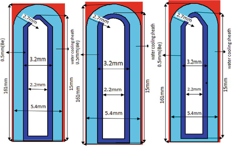
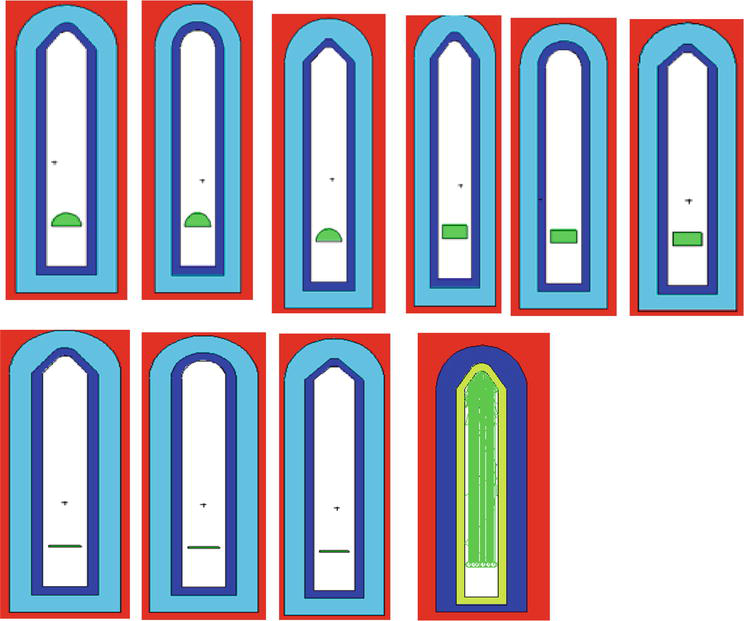
In this study, hemispherical-conical, hemispherical, and truncated-conical miniature X-ray tubes [6, 8] simulated with the Monte Carlo code MCNPX (2.6.0) were used (Figure 1). In these simulations, the densities of tungsten, beryllium, and water were 19.3, 1.84, and 0.998 g/cm3 according to the Reference [7], and the density of the carbon layer was 1.35 gr/cm3 according to the Reference [8, 9]. The F6 tally was applied to calculate random heat as an absorbed dose estimator. We simulated the transport of photons and electrons (Mode: P E) with the cut-off energy of 1 Kev 1). According to Figure 2, each miniature X-ray tube included two main parts called the electron production source (cathode) and anode (the electron collision site). Thus, the hemispherical (r = 0.8 mm radius), cylindrical (height = 0.8 mm and r = 0.8 mm), and disk-shaped (r = 0.8 mm and thickness = 0.1 mm) cathode structures were used in all stages of the work. The name of the tube indicates the anode structure. In all phases of the study, miniature tubes were placed in the spherical water phantom.
Figure 1.
A view of miniature X-ray tubes simulated for conducting the study.
Figure 2.
Simulated miniature tubes with electronic source.
2.2 Calculation of the dose using cold carbon cathode (cylindrical and spherical) for production of electrons
Axial dose (parallel to the main axis of the X-ray tube) and transverse dose (perpendicular to the main axis of the X-ray tube) were 0.5–10 cm from the active center of the electron generating source. These dosages were calculated and compared for miniature tubes (Figure 2) using the F6 tally for the energies of 40, 45, and 50 Kev. During the calculation of the axial and transverse doses using a cold carbon source (cylindrical and spherical) in all the three tubes, the average run times of programs were equal to 2670 min and 3660 min for cylindrical and spherical sources, respectively. Moreover, the average statistical error for the first 10 cells was equal to 2.5 and 3% for the cylindrical and spherical sources, respectively. Finally, for the next 10 cells, in each axis, they were equal to 4.5 and 4.7% for the cylindrical and spherical sources, respectively.
2.3 Calculation of the X-rays spectra using a cylindrical cold carbon source
The X-ray spectra of the cylindrical cold carbon cathode (r = 0.8 mm and h = 0.8 mm) were obtained for miniature X-ray tubes using the F5 ring tally at a distance of 2.5 cm from the active center of the source (the origin of the coordinates) on the longitudinal and transverse axes for 50 Kev energy (Figure 2). The average program run times for transverse and axial dose calculations were 2600 min and 2580 min, respectively. Moreover, the mean history of the target colloidal particles for the both axes was approximately 2 × 10⁹.
2.4 Calculation of the axial and transverse doses using a disc-shaped source
To compare the axial and transverse doses and the running particles using hot and cold cathodes, a disk with r = 0.8 mm and thickness = 0.1 mm was evaluated in two stages: once with tungsten density (the hot cathode) and once with carbon density (the cold cathode). Tables 1 and 2 show the results.
The cold cathode (carbon)
The hot cathode (tungsten)
Number of running particles
Run time
Number of running particles
Run time
Hemispherical-conical
2,144,007,572
3782
1,507,221,585
6000
Hemispherical
2,139,594,043
4007
1,368,439,172
6000
Truncated-conical
2,139,299,717
4022
1,359,805,034
6000
Table 1.
Comparison of the number of running particles with the tungsten and carbon cathodes during the calculation of the axial dose.
The cold cathode (carbon)
The hot cathode (tungsten)
Number of running particles
Run time
Number of running particles
Run time
Hemispherical-conical
2,138,885,625
3950
1,362,548,727
6000
Hemispherical
2,142,968,016
4022
1,448,481,725
6000
Truncated-conical
2,141,088,748
4037
1,352,237,802
6000
Table 2.
Comparison of the number of running particles with the tungsten and carbon cathodes during the calculation of the transverse dose.
3.1 Doses of hemispherical and cylindrical carbon electron sources (the cold cathode)
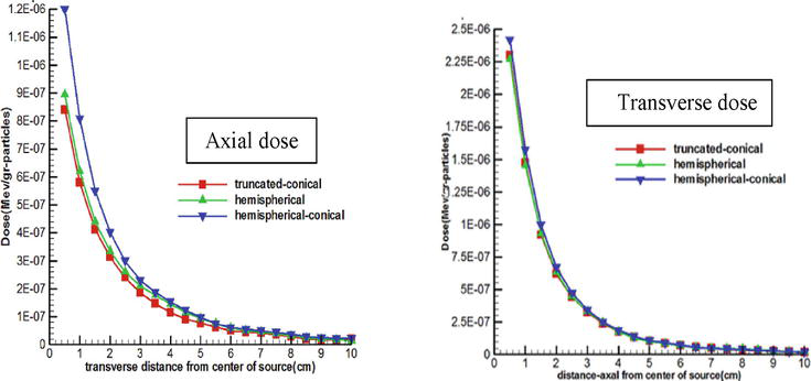
As shown in Figures 3 and 4, the axial and transverse doses were obtained for hemispherical, hemispherical-conical, and truncated-conical miniature X-ray tubes using 50 Kev energy in the range of 0.5–10 cm, and an electron source (the cold cathode) was selected.
Figure 3.
The axial and transverse doses using a hemispherical cold cathode.
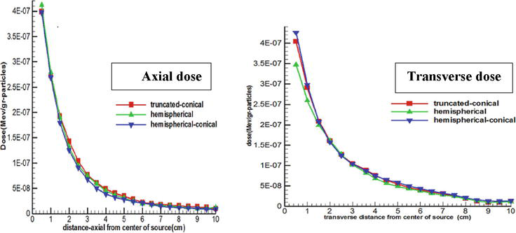
Figure 4.
The axial and transverse doses using a cylindrical cold cathode.
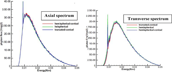
3.2 Spectra of a cylindrical carbon electron source (the cold cathode)
As shown in Figure 5, hemispherical-conical, hemispherical, and truncated-conical X-ray spectra of miniature X-ray tubes were obtained along the longitudinal and transverse axes for 50 Kev energy at a distance of 2.5 cm from the active center of the source. Characteristic X-ray energy peaks appeared in 8.7 Kev and 10.2 Kev positions.
Figure 5.
Axial and transverse spectra using a cylindrical cold cathode.
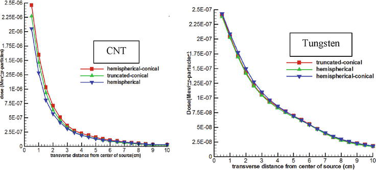
3.3 The axial and transverse doses of disc-shaped electron sources
The axial and transverse doses for hemispherical-conical, hemispherical, and truncated-conical miniature X-ray tubes using 50 Kev energy in the range of 0.5–10 cm by selecting two disk-shaped electron sources (the cold and hot cathodes) are shown in Figures 6 and 7.
Figure 6.
The axial doses using the hot and cold cathodes.
Figure 7.
The transverse doses using the hot and cold cathodes.
3.4 Running particles of a disc-shaped source
Tables 1 and 2 present the number of running particles for hemispherical-conical, hemispherical, and truncated-conical miniature X-ray tubes using disk-shaped tungsten (the hot cathode) and carbon (the cold cathode) electron sources with the same radius and thickness.
4.1 Investigation of the source of carbon electron production in the form of spherical and cylindrical cold cathodes
In this section, the doses obtained from the spherical and cylindrical cold cathodes (Figures 3 and 4, respectively) with the same radius were compared on the longitudinal and transverse axes. As can be observed, the mean ratios of the axial and transverse doses were obtained as 5.4, 4.8, and 4.6 as well as 2.4, 2.2, and 1.8 for spherical to cylindrical cathodes in hemispherical-conical, hemispherical, and truncated-conical miniature tubes, respectively. These results showed that the spherical cold cathode was more efficient in the production of transverse and axial doses than the cylindrical cold cathode with the same radial. Further, Figures 3 and 4 show that the hemispherical-conical X-ray tube compared to the two hemispherical and truncated-conical miniature tubes was more efficient in producing axial and transverse doses (with a spherical cold source) and transverse dose (with a cylindrical cold source). This indicated that different forms of cathode affected the output of the X-ray source in the simulation.
4.2 Analysis of the spectra of the cylindrical cold cathode
The graphs in Figure 5 show that when using a cylindrical cold cathode, the peak of the hemispherical-conical and hemispherical graphs is higher than the rest in the transverse and axial spectra. Moreover, the larger area under the graph in the hemispherical-conical miniature tube confirmed the efficiency along the transverse axis. This means that when using a hemispherical-conical miniature x-ray tube along the transverse axis, the cylindrical cold cathode outperforms others.
4.3 Analysis of the application results of the disk-shaped carbon and tungsten electron sources
In this section, the axial and transverse doses (according to Figure 6) and electron production (based on Tables 1 and 2) were compared in terms of three hemispherical-conical, hemispherical, and truncated-conical miniature X-ray tubes. For this purpose, a disk-shaped tungsten and a carbon layer with the same thickness and radius as an electron source were used. The number of running electrons for the transverse dose of the carbon layer was 1.5, 1.47, and 1.58. Meanwhile, for the axial dose of the carbon layer, the number was 1.42, 1.56, and 1.57 times the tungsten layer, respectively, for hemispherical-conical, hemispherical, and truncated-conical X-ray tubes. In addition, the average run time of each program using carbon and tungsten layers based on Tables 1 and 2 was 3970 and 6000 min, respectively. The mean ratio of the transverse and axial doses of the carbon source to the tungsten source was obtained to be 4.8, 4.1, and 4.4 as well as 7.4, 6.7, and 7.9 for hemispherical-conical, hemispherical, and truncated-conical tubes, respectively.
Overall, based on the results of this study, the following conclusions can be made:
The data of graphs, spectra, and tables show that the geometric structure (forms of cathode and anode and their material) affects the output of miniature X-ray tubes. In this work, this parameter had the greatest impact on the hemispherical-conical miniature X-ray tube.
The data in the tables show that the cold cathode responds in a shorter time than the hot cathode, and the number of running particles was much more with the cold cathode than with the hot cathode. In brief, the carbon cathode had a higher dose than the tungsten cathode.
According to the calculated dose, the hemispherical-conical miniature X-ray tube (similar to the tube used in the Axxent system) was in the first place, and the hemispherical miniature X-ray tube (similar to the tube used in the Intrabeam system) was in the second place.
Where Jc(Acm2) and Ac=120Acm2.k are constant values that are the same for all ionic heat emitters.
The temperature is in Kelvin, K=8.6×10⁻⁵evk is the Boltzmann’s constant, and Φ (eV) is the cathode work function. Temperature and the work function had the greatest effect on thermionic emission, and the effect of Ac was negligible. To prevent cathode evaporation, the string temperature must have the lowest value; thus, it needs to have a small work function.
Appendix 2
The field emission of electrons from a surface to the vacuum using quantum mechanical tunneling is extremely high in response to an electric field. In general, in such a material, electrons at the Fermi surface must overcome the potential barrier applied by the work function (Φ) in the presence of an external electric field and change the potential barrier before escaping to the vacuum. In this process, the two quantities are of great importance: T (e), which is the probability of passing electrons through the barrier, and N (e), which is the source of colliding electrons. T (e) depends on the width of the barrier, which, in turn, depends on the applied field and work function of the materials. On the other hand, N (e) depends on the bond structure of the materials and the distribution of the electron at a certain temperature. Assuming that the free-electron band structure of a metal is at 0 K temperature, the emission current follows the Fowler-Nordheim law.
J=AFNΦt2(y).ELocal2exp(−BFN.Φ1.5ELocal.V(y))E2
To extract large currents, either Elocal must be increased or the work function (Φ) must be reduced.
References
1.Gazda M, Lawrence R. Principles of Radiation Therapy, Cancer Management: A Multidisciplinary Approach. 2013
2.Sun Y. Design and Fabrication of Carbon Nanotube Array Based Field Emission Cathode for X-Ray Tube. 2013
3.Sugie H, Tanemura M, Filip V, Iwata K, Takahashi K, Okuyama F. Carbon nanotubes as electron source in an x-ray tube. Applied Physics Letters. 2001;78(17):2578-2580
4.Filip V, Filip L, Okuyama F. Miniature x-ray tubes: Current state and future prospects. Journal of Instrumentation. 2013;8(03):T03005
5.Barati B, Zabihzadeh M, Birgani MJT, Chegini N, Ghahfarokhi MH, Fatahiasl J. Assessment of two hemispherical and hemispherical-conical miniature sources used in electronic brachytherapy using Monte Carlo simulation. Electronic Physician. 2017;9(2):3845
6.Barati B, Zabihzadeh M, Birgani MT, Chegini N, Fatahiasl J, Mirr I. Evaluation of the effect of source geometry on the output of miniature X-ray tube for electronic brachytherapy through simulation. Journal of Biomedical Physics & Engineering. 2018;8(1):29
7.McConn RJ, Gesh CJ, Pagh RT, Rucker RA, Williams III R. Compendium of Material Composition Data for Radiation Transport Modeling. Richland, WA (United States): Pacific Northwest National Lab(PNNL); 2011
8.Collins PG, Avouris P. Nanotubes for electronics. Scientific American. 2000;283(6):62-69
9.Milne W, Teo K, Mann M, Bu I, Amaratunga G, De Jonge N, et al. Carbon nanotubes as electron sources. 2006;203(6):1058-1063
Written By
Barat Barati, Masumeh Kaydani, Fariba Farhadi Birgani, Mansour Zabihzadeh, Mohammad Javad Tahmasebi and Nahid Chegeni
Submitted: 22 April 2023Reviewed: 22 April 2023Published: 23 February 2024