Open Access is an initiative that aims to make scientific research freely available to all. To date our community has made over 100 million downloads. It’s based on principles of collaboration, unobstructed discovery, and, most importantly, scientific progression. As PhD students, we found it difficult to access the research we needed, so we decided to create a new Open Access publisher that levels the playing field for scientists across the world. How? By making research easy to access, and puts the academic needs of the researchers before the business interests of publishers.
We are a community of more than 103,000 authors and editors from 3,291 institutions spanning 160 countries, including Nobel Prize winners and some of the world’s most-cited researchers. Publishing on IntechOpen allows authors to earn citations and find new collaborators, meaning more people see your work not only from your own field of study, but from other related fields too.
The purpose of the study was to assess the state and degree of exhaustion of turbine rotor materials made of low-alloy Cr-Mo-V steels after long-term operation. The tests were carried out for selected structure states defined on the basis of images of the structure observed using a scanning electron microscope, and the degree of development of precipitation processes based on the X-ray analysis of the phase composition of electrolytically isolated carbide deposits. For materials with such defined structure states and degree of development of precipitation processes, the following were determined: mechanical properties at room and elevated temperatures, residual life and available residual life on the basis of short-term creep tests, and creep rate from creep curves for temperature and stress parameters corresponding to operational parameters. Based on the results of short-term creep tests conducted at a temperature higher than the operational temperature and with a stress corresponding to the operational life, residual and available residual life were determined and the degree of exhaustion was estimated.
Łukasiewicz Research Network — Upper Silesian Institute of Technology, Gliwice, Poland
Janusz Dobrzański
Łukasiewicz Research Network — Upper Silesian Institute of Technology, Gliwice, Poland
*Address all correspondence to: joanna.furmanek@git.lukasiewicz.gov.pl
1. Introduction
Łukasiewicz Research Network — Upper Silesian Institute of Technology (formerly Łukasiewicz Research Network — Institute for Ferrous Metallurgy) has been carrying out research for several decades, aimed at creating diagnostic rules, developing methods and methodology for assessing the service life of critical components of the pressure part of power units, i.e. those operating in the most difficult temperature and stress conditions in a time significantly exceeding the design time [1, 2, 3, 4, 5, 6, 7, 8, 9, 10]. These works cover various issues, including the development of a methodology to assess the condition of these components and forecast their further safe operation. The tools for assessing materials include a database in the field of properties and structure after use of materials applied in these components. For the proper assessment of the material condition, it is necessary to classify the condition of the structure in relation to the degree of exhaustion, which prove the condition of the assessed material and its suitability for further operation. Critical components operating above the limit temperature, i.e. in conditions where creep is the main or significant destruction process that determines changes in the material during operation, include components of the pressure part of the boiler and turbine, which include rotor shafts. It is also important to determine the type of carbides and their impact on the performance properties of rotor steels [11, 12, 13]. The paper covers the issues of assessing the suitability of the rotor material for operation after exceeding the design operating time, assessing their microstructural state and the set of functional properties corresponding to this structure. It is a response to the needs of the professional power industry in terms of conducting a reliable assessment of the condition and a reliable forecast of further safe operation in the conditions expected and defined by the owners of such facilities, especially for components whose actual service life exceeded the design time.
The material for the tests consisted of sections of the medium-pressure SP and high-pressure HP parts of the TK200 and 18 K360 steam turbine rotors of power units with a nominal power of 200 and 360 MW after long-term operation significantly exceeding the unit’s design operating time of 100,000 hours, made of low-alloy ternary Cr-Mo-V steel (21HMF).
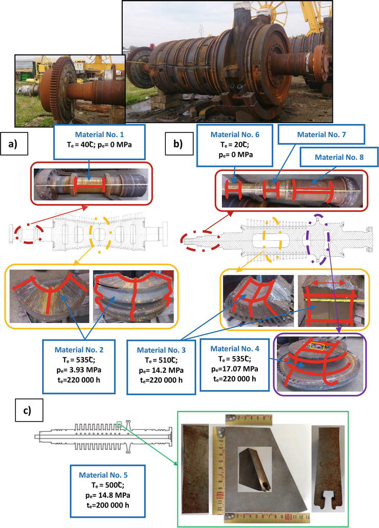
To obtain representative material for testing, it was assumed that it should be characterised by a structure from one that did not differ from that characteristic of the initial state to a structure that was quite degraded. The choice of locations for testing was determined by design parameters for individual areas, as well as preliminary structure tests. Detailed locations from which the material for destructive testing was taken and their operational parameters are shown in Figure 1 (material No. 1–5).
Figure 1.
Method and location of sampling from steam turbine rotors made of Cr-Mo-V steel (21HMF) after long-term operation, significantly beyond the unit’s design operating time.
The results of the control analysis of the chemical composition of the materials under test and the required chemical composition of the tested Cr-Mo-V (21HMF) steel intended for forged rods and turbine shaft forgings according to the PN-75/H-84024 standard are summarised in Table 1.
Steel grade
Item ID
Element content, [%]
C
Mn
Si
P max.
S max.
Cr
Ni max.
Mo
V
Cr-Mo-V (21HMF)
Material 1
0.22
0.35
0.33
0.007
<0.003
1.40
0.55
1.08
0.32
Material 2
0.22
0.37
0.34
0.011
< 0.003
1.41
0.58
0.97
0.30
Material 3
0.21
0.49
0.23
0.009
0.012
1.24
0.55
0.80
0.27
Material 4
0.20
0.48
0.23
0.007
0.010
1.22
0.55
0,80
0.27
Material 5
0.23
0.46
0.33
0.009
0.012
1.28
0.51
1.08
0.29
PN-75/H-84024 1975
0.17 ÷ 0.25
0.30 ÷ 0.50
0.30 ÷ 0.60
0.035
0.035
1.20 ÷ 1.50
0.60
1.0 ÷ 1.2
0.25 ÷ 0.35
Table 1.
Control analysis of the chemical composition of the tested materials of steam turbine rotors after long-term operation and requirements for low-alloy ternary Cr-Mo-V steel (21HMF).
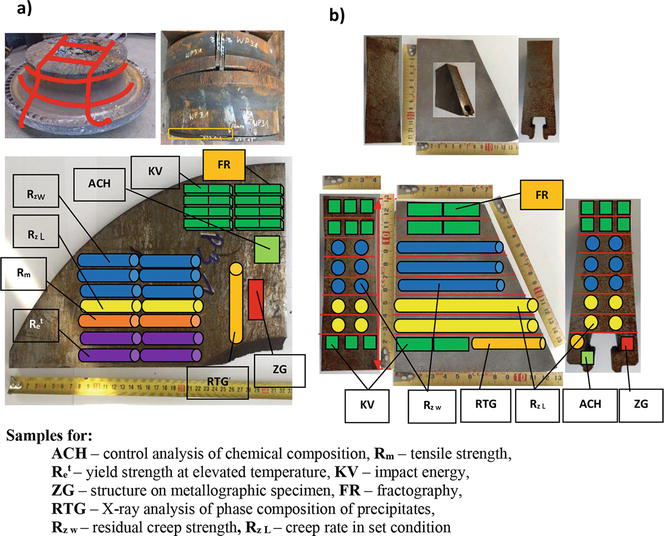
The method of collecting samples for carrying out particular types of destructive material tests is shown graphically in Figure 2 on the example of the material of the HP high-pressure part of the 18 K360 turbine rotor, No. 4 (Figure 2a), and the material of the HP high-pressure part of the TK 200 turbine rotor, No. 2b.
Figure 2.
Type and location of sampling for destructive testing of the material of steam turbine rotors after long-term operation significantly beyond the unit’s design operating time, on the example of: (a) material of the HP high-pressure part of the 18 K360 turbine rotor, No. 4, (b) material of the HP high-pressure part of the TK 200 turbine rotor, No. 5.
3. Methodology of assessing the condition of the structure depending on the degree of exhaustion
An objective assessment of the durability of a material operating in creep conditions is possible only on the basis of a set of materials science methods and research techniques, including results of microstructure examination, examination of mechanical properties and calculation methods.
The material of the components of the pressure part of the boiler, pipelines and turbine operating in creep conditions or with a significant percentage of creep is assessed using non-destructive and destructive methods. The selection of diagnostic methods for assessing the condition of the material is made each time depending on the type of component, its operating time in relation to the assumed design time and the nature of its operation. Regardless of the service life, an assessment of the material microstructure is required. Its purpose is to determine the class of microstructure based on observations using a scanning electron microscope and to estimate the degree of material exhaustion. They determine its ability to carry operating loads. In addition, they allow to determine the working time until the next inspection, which is a safe time for further operation.
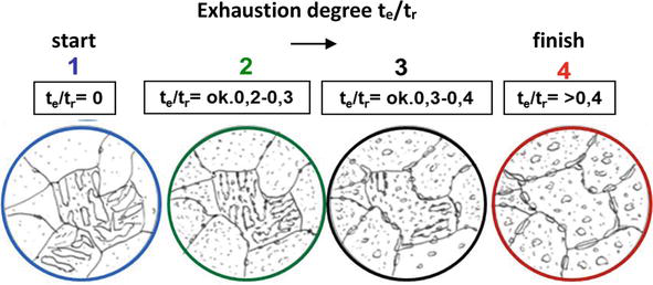
Based on the results of many years of own research, patterns of structure were developed, illustrating the successive stages of its changes defined in the prepared classifications, including for the tested steel [1, 2, 3, 4, 5, 6, 7, 8, 9, 10]. The structure change model related to the degree of exhaustion defined as the ratio of service life te to expected time to failure tr for low-alloy ternary ferritic-bainite steels is shown in Figure 3. This model is also applicable to the low-alloy Cr-Mo-V (21HMF) steel, being the subject of this study.
Figure 3.
Model for microstructural evolution in ferritic-pearlitic steels [3].
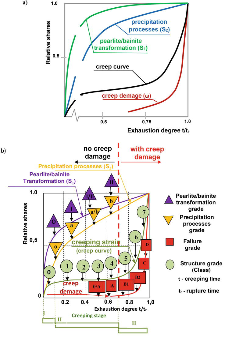
The methodology for assessing the condition of low-alloy Cr-Mo and Cr-Mo-V steels operating in creep conditions based on changes in the microstructure based on constituent processes, in relation to the degree of exhaustion, is shown graphically in Figure 4. In the case of this group of steels, the constituent processes determining changes in the structure as a result of exploitation include pearlite/bainite disintegration, development of precipitation processes and internal damage processes as a result of creep. The dynamics of their changes depending on the degree of exhaustion are shown in Figure 4a. On the other hand, Figure 4b shows the classes of constituent processes and the corresponding main class of structure related to the creep stage and the degree of exhaustion.
Figure 4.
Classification method of material condition on the basis of changes in the structure based on constituent processes in relation to the degree of exhaustion for ferritic-pearlitic steels used under creep conditions [3].
The developed classification consists of two parts. The first part of the classification includes tested steels after use without internal damage. The second part of the classification consists of changes, developed for materials with internal damage due to creep, in the structure depending on the degree of exhaustion [1, 3]. This publication is limited only to the assessment of material conditions without internal damage caused by creep.
4.1 Structure observed using scanning electron microscope
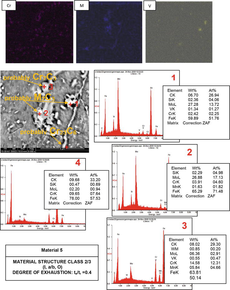
Microstructure examination was carried out on etched metallographic specimens taken from fragments of sections of material of steam turbine rotors. The structure was observed using a scanning electron microscope. They included the assessment of the state of the basic phase components, assessment of the state of development of precipitation processes and the state of development of internal damage resulting from the effects of long-term operation load. The assessment of the structural condition was performed in accordance with Łukasiewicz-GIT’s (Łukasiewicz Research Network – Upper Silesian Institute of Technology) own classification in the form of a structure class and the corresponding degree of exhaustion determined on the basis of the state of bainitic areas for the revealed ferritic-bainitic structure and the degree of development of precipitation processes and the state of internal damage. In the assessment of the degree of development of precipitation processes, tables of chemical composition from selected micro-areas, including precipitates, were also used, as well as maps of distribution and concentration of selected elements (the map of precipitates for material No. 5 is shown in Figure 5). Representative images illustrating the state of structural components are shown in Figure 6. A description of the state of the structure and the assessment result obtained are presented in Table 2.
Figure 5.
Example of assessment of the probability of occurrence of particular types of carbide precipitates on the basis of maps of occurrence and intensity of selected carbide-forming elements, chemical composition of micro-areas and morphological features in the material of a steam turbine rotor made of Cr-Mo-V (21HMF) steel after long-term operation.
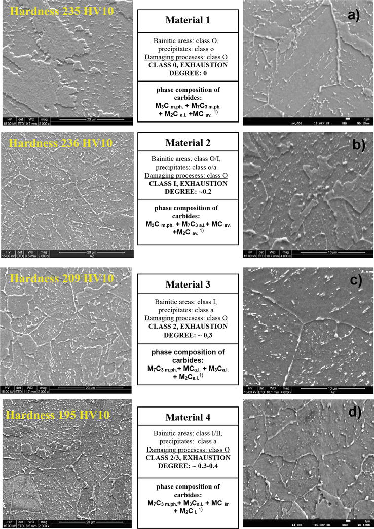
Figure 6.
Determined classes of structure, classes of development of precipitation processes and degree of exhaustion of turbine rotor materials made of Cr-Mo-V steel (21HMF) after long-term operation in relation to the initial state.
Bainitic-ferritic structure. Bainite with numerous, mostly fine, precipitates. The image of the microstructure is similar to the typical microstructure of the initial state of the rotor material from the tested steel. The initiation of internal damage processes is not disclosed. No discontinuities or microcracks were observed in the structure.
Bainitic structure with few ferrite grains. The material is characterised by bainite plates with precipitates at the borders of the plates and a small amount inside them. A significant number of fine precipitates were observed within these areas, which can be identified by their morphological features: finely dispersed as VC precipitates and small elongated Mo2C. In addition, M3C cementite in the form of larger precipitates was observed. The initiation of internal damage processes is not disclosed. No discontinuities or microcracks were observed in the structure.
Bainitic-ferritic structure. The material is characterised by a partial disappearance of the plates and numerous precipitates on the borders of the plates and inside them. Precipitates, probably of M7C3 carbide forming chains, were observed on the boundaries of bainite plates. Also, within these areas, a significant number of precipitates were observed, which, based on their morphological features, can be identified as VC and Mo2C precipitates. The partial disappearance of bainite plates is confirmed by the lower hardness. No initiation of internal damage processes was observed. No discontinuities or microcracks were observed in the structure.
Bainite with few areas of ferrite. Bainite areas with significant loss of bainite plates are characterised by an advanced precipitation process, which is evidenced by numerous precipitates within these areas. Based on their morphological features, it can be assumed that they are fine spheroidal precipitates of vanadium-rich MC carbide and elongated precipitates of molybdenum-rich M2C carbide. The numerous chain-forming precipitates occurring on the borders of these areas are probably precipitates of M23C6 carbide rich in chromium. No initiation of internal damage processes was observed. No discontinuities or microcracks were observed in the structure.
(I/II, a, O) 1) class 2/3 te/tr = ⁓0.3–0.4
195
Material 5
500 14.80
Bainitic-ferritic structure. Bainite with few areas of ferrite. Partial or significant disappearance of bainite areas with a simultaneous significantly advanced precipitation process. Numerous precipitates within bainite areas and on grain boundaries forming chains. No initiation of internal damage processes was observed. No discontinuities or microcracks were observed in the structure.
(I, a/b, O)1) class 2/3 te/tr = ⁓0.4
211
Table 2.
Results of microstructure examination on etched metallographic specimens of tested materials of steam turbine rotors made of Cr-Mo-V steel (21HMF) after operation outside the design working time of the unit, determined class of structure, corresponding degree of exhaustion and hardness.
Notes: 1) I – class of bainite disintegration degree, a – class of carbide precipitation processes development, O – class of internal damage processes development.
Material No. 1 from the SP part of the rotor, where the operating temperature is close to room temperature and is about 40°C, is characterised by bainite with quite numerous precipitates. The image of the microstructure corresponds to the typical microstructure of the initial state of the rotor material from the tested steel (Figure 6a). The results of analyses of the chemical composition of micro-areas including precipitates, as well as the X-ray analysis of precipitates collected electrolytically showed the presence of iron-rich M3C cementite as the main carbide phase, chromium-rich M7C3 carbides and small MC precipitates rich in vanadium in a large amount and a small amount of M2C carbides rich in molybdenum (Figure 7a). In addition, the image of the structure and the state of development of the precipitation processes correlate with the hardness of about 235 HV10 — a level corresponding to the initial state of the rotor material from the tested steel. The material was assigned in accordance with the methodology described in point 3 of the study to class O and the degree of exhaustion tr/te = 0.
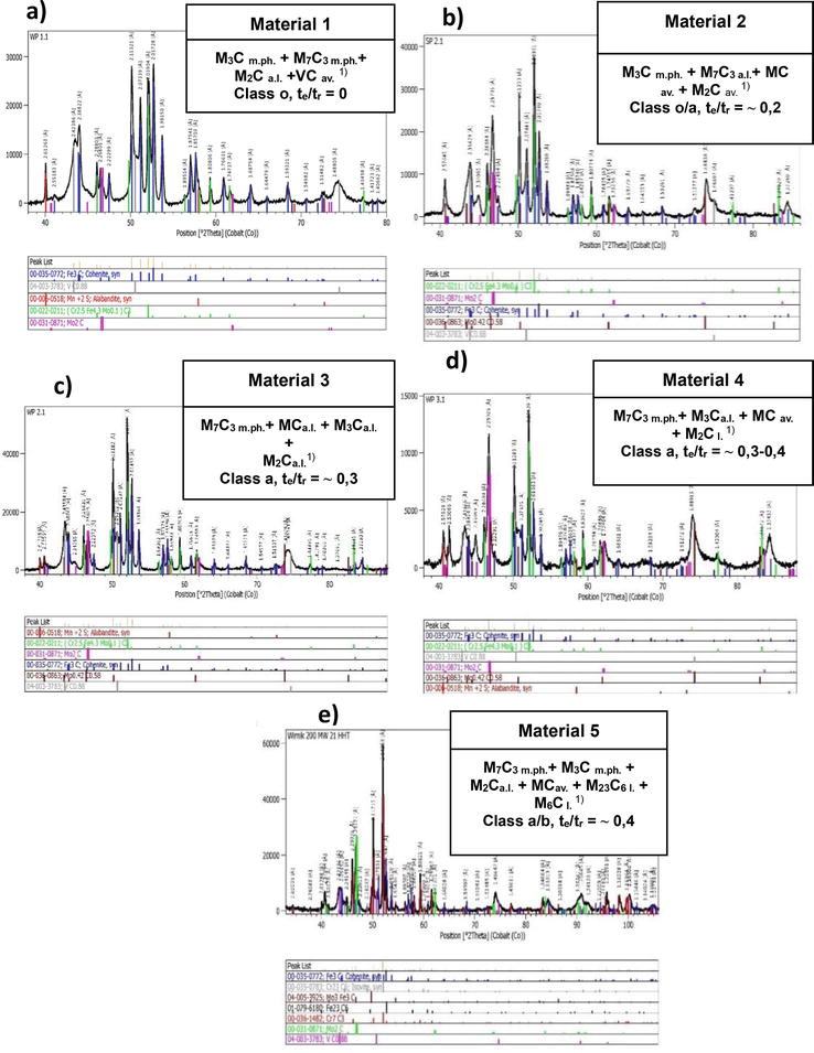
Figure 7.
X-ray diffractograms of material precipitate isolates of tested material sections from steam turbine rotors with the phase composition of precipitates and the estimated class of development of carbide precipitation processes in low-alloy Cr-Mo-V steel (21HMF) after long-term operation above the limit temperature, significantly beyond the design working time. Comments: 1) M.ph.-main phase, l.-little, a.l.-a lot, v.l.-very little, av.-at an average.
Material No. 2 from the SP part of the rotor, where the operating temperature was 535°C, is characterised by bainite with quite numerous precipitates on the boundaries of the plates and inside them (Figure 6b). Partially preserved bainite plates can be observed in the material of the studied area. Precipitates, probably of chromium-rich M7C3 carbide, forming chains, were observed on the boundaries of the bainite plates. Also, within these areas, a significant number of fine precipitates were revealed, which, based on their morphological features, can be identified as vanadium-rich MC precipitates, significant M3C cementite precipitates and small elongated molybdenum-rich M2C precipitates. The image of the structure corresponds to the level of hardness, which does not differ from that characteristic for the initial state and amounts to approx. 236 HV10. The material was assigned in accordance with the methodology described in point 3 of the study to class 1 and the degree of exhaustion tr/te = ⁓ 0.2.
Material No. 3 from the HP part of the rotor, where the operating temperature was 510°C, is characterised by bainite with numerous precipitates on the boundaries of the plates and inside them (Figure 6c). Partial disappearance of bainite plates can be observed in the material of the examined area. Precipitates, probably of chromium-rich M7C3 carbide, forming chains, were observed on the boundaries of bainite plates. Also, within these areas, a significant number of precipitates were revealed, which by their characteristics can be identified as vanadium-rich MC precipitates, numerous M3C cementite precipitates and small elongated molybdenum-rich M2C precipitates. The partial disappearance of bainite plates was also confirmed by the lower hardness. The material was assigned in accordance with the methodology described in point 3 of the study to class 2 and the degree of exhaustion tr/te = ⁓ 0.3.
Material No. 4 from the HP part of the rotor, where the operating temperature was 535°C, is characterised by bainite with numerous precipitates on the boundaries of the plates and inside them (Figure 6d). A significant disappearance of the bainite plates can be observed in the material of the examined area. Precipitates, probably of M7C3 carbide with a significant chromium content, forming chains, were observed on the boundaries of bainite plates. Also, within these areas, a significant number of precipitates were revealed, which, based on their morphological features, can be identified as coagulated M3C cementite precipitates, fine vanadium-rich MC precipitates and a few molybdenum-rich M2C precipitates. The number and size of precipitates confirm a significant degree of changes in this area as a result of long-term operation, and their type and share were confirmed by the results of the X-ray phase analysis of precipitate deposits (Table 3). The material was assigned in accordance with the methodology described in point 3 of the study to class 2/3 and the degree of exhaustion tr/te = ⁓ 0.3–0.4.
Tested material
Identified phase components and their relative content
Class of the degree of development of precipitates Exhaustion degree te/tr
1
2
3
Material 1
M3C– main phase M7C3– main phase M2C – a lot VC– average
Class: o 0
Material 2
M3C– main phase M7C3– main phase M2C – average MC – average
Class: o/a approx. 0.2
Material 3
M7C3– main phase M3C – a lot M2C – a lot MC – a lot
Class: a approx. 0.3
Material 4
M7C3– main phase M3C – a lot MC – average M2C – little
Class: a approx. 0.3–0.4
Material 5
M7C3– main phase M3C – main phase M2C – a lot MC – average M23C6 – little M6C – little
Class: a/b approx. 0.4
Table 3.
Results of X-ray phase analysis of deposits of electrolytically isolated precipitates of tested materials of steam turbine rotors made of low-alloy Cr-Mo-V (21HMF) steel after operation significantly beyond the unit’s design operating time.
Material No. 5 from the HP part of the rotor, where the operating temperature was 535°C, is characterised by bainite with few areas of ferrite. Partial or significant disappearance of the bainite plates with a simultaneous significantly advanced precipitation process can be observed in the material of the examined area. Numerous precipitates, quite evenly distributed within the bainite areas, and chain-forming precipitates were observed on grain boundaries. In addition to the types of precipitates revealed in the other tested materials, the presence of M23C6 and M6C carbides on grain boundaries was observed inside the grains, which confirms the degree of advancement of the precipitating processes in this material. The disclosed state of the structure was also confirmed by the level of hardness. The material was assigned in accordance with the methodology described in point 3 of the study to class 2/3 and the degree of exhaustion tr/te = ⁓ 0.4.
4.2 X-ray phase analysis of precipitates
The type and amount of precipitates were plotted on an electrolytically isolated deposit of precipitates from the tested materials. The obtained results in the form of X-ray diffraction patterns of precipitates electrolytically isolated for the above materials are shown in Figure 7, while Table 3 shows the phase composition and the share of precipitates based on the identification of the obtained X-ray diffraction patterns. On this basis, the class of the degree of development of the precipitation processes for the tested materials from the turbine shafts after long-term operation, and the corresponding degree of exhaustion were determined in accordance with Łukasiewicz-GIT (Łukasiewicz Research Network – Upper Silesian Institute of Technology) own classification, which is summarised in Table 3.
The class of development of carbide precipitation processes corresponds to their sequence revealed in X-ray examinations of isolated precipitates. The state of development of precipitation processes corresponds to:
- material No. 1 class o and degree of exhaustion te/tr = ⁓ 0,
- material No. 2 class o/a and degree of exhaustion te/tr = ⁓ 0.2,
- material No. 3 class a and degree of exhaustion te/tr = ⁓ 0.3,
- material No. 4 class a and degree of exhaustion te/tr = ⁓ 0.3–0.4,
- material No. 5 class a/b and degree of exhaustion te/tr = ⁓ 0.4,
which confirms the existence of a diverse structure with varying degrees of exhaustion.
The predicted sequence of precipitates as a result of the creep process of the tested low-alloy Cr-Mo-V (21HMF) steels based on previous test results is [10]:
M3C m.ph. + VC av. + M2C av. → M23C6 m.ph. + M2C + M3C + VC → M6C m.ph. + M7C3 av. + M23C6 av. + M2C + VC → M6C m.ph. +M23C6 + M2C + VC.
In assessing the degree of development of precipitation processes, the results of chemical composition tests from selected micro-areas, including precipitates, and maps of distribution and concentration of selected components were also used. A map of precipitates together with the results of the X-ray analysis of the chemical composition of micro-areas and an image of the microstructure obtained using a scanning electron microscope for material No. 5 is shown in Figure 5.
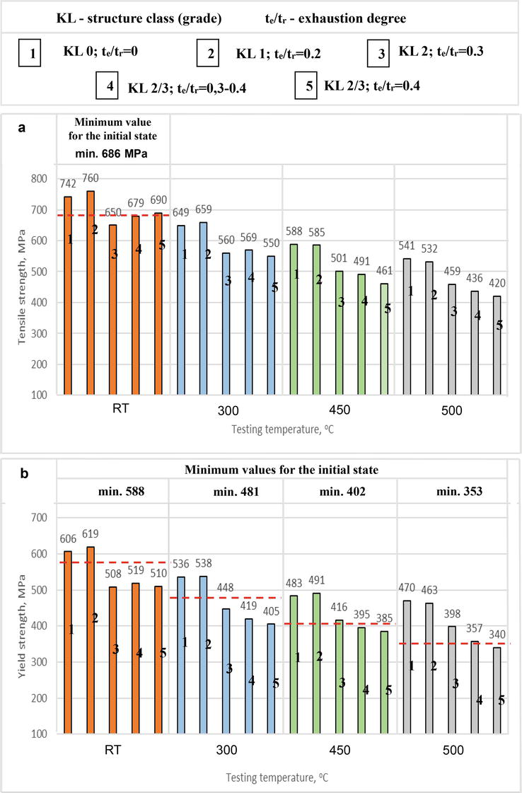
The examination of strength properties, that is, tensile strength Rm, yield strength Re at room temperature, yield strength Ret at three temperature levels, that is. 300, 450 and 500°C, and elongation A5 and reduction of area Z were carried out at room temperature RT and at elevated temperature as above. The obtained results of examining the materials of the sections of the high-pressure and medium-pressure parts of the turbine shaft are shown in Figures 8 and 9.
Figure 8.
Tensile strength (a) and yield strength (b) at room and elevated temperatures of turbine rotor materials after long-term operation of various structure classes and the corresponding degree of exhaustion in relation to the initial state.
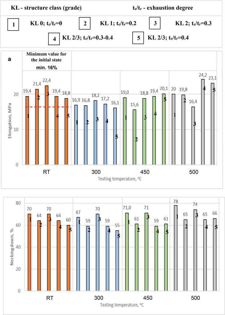
Figure 9.
Elongation (a) and reduction of area (b) in a tensile test at room and elevated temperatures of turbine rotor materials after long-term operation of various structure classes and the corresponding degree of exhaustion in relation to the initial state.
The obtained results show that with an increase in the degree of structure degradation measured by its class and an increase in the corresponding degree of exhaustion, the strength properties decrease. Tensile strength and yield strength at room temperature are higher than the minimum required values for turbine rotor shaft forgings made of the tested low-alloy Cr-Mo-V steel (21HMF) for a material with a structure characteristic of the initial state and a material with a low degree of exhaustion (te/tr = ⁓ 0.2). For the tested materials with a higher class of structure and a higher degree of exhaustion (te/tr = > 0.2 to 0.4), these properties are clearly reduced, and the actual values of yield strength at an elevated temperature are lower than the minimum required for the initial state (Figure 8). The elongation values obtained in the tensile test carried out at room temperature, regardless of the structure class and the corresponding exhaustion degree (te/tr = 0–0.4), meet the minimum requirements at room temperature for turbine shaft forgings made of the tested steel in the initial state. Elongation at elevated temperature and reduction of area at room and elevated temperature, regardless of the structure class and degree of exhaustion, are at a sufficiently high level.
To determine impact energy at room temperature, impact tests were performed on samples with a V notch. The results of these tests for the tested materials made of low-alloy Cr-Mo-V (21HMF) steel after long-term operation with different structure class and corresponding degree of exhaustion (materials No. 2–4) regarding the typical structure of the initial state (material No. 1) is presented graphically in Figure 10.
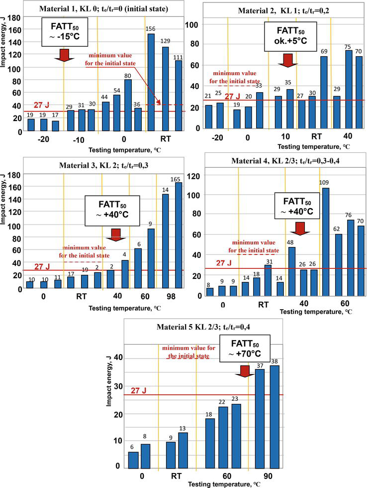
Figure 10.
Impact energy depends on the test temperature and fracture appearance transition temperature (FATT50) of steam turbine rotor materials made of Cr-Mo-V (21HMF) steel after long-term operation with different structure class and corresponding degree of exhaustion in relation to the initial state.
The results of impact tests at room temperature of material No. 1 with a structure characteristic of the initial state (te/tr = 0) and material No. 2 with minor changes in structure (te/tr = ⁓ 0.2) meet the requirements for the initial state as and the expected minimum impact energy of 27 J. With an increase in the structure class and an increase in the degree of exhaustion (materials No. 3–5), the value of impact energy decreases and the tested materials do not meet the minimum requirements for the initial state at room temperature and are below the minimum expected value of 27 J. Also, the determined fracture appearance transition temperature (FATT50) for the tested materials increases with the level of structure degradation measured by the structure class and the corresponding degree of exhaustion. Only for the material corresponding to the initial state (material No. 1) is the brittle transition temperature negative (−15°C). For the remaining materials it is positive, which is an unfavourable feature of the tested materials and increases from +5°C for material No. 2 (te/tr = ⁓ 0.2) to +70°C for material No. 5 (te/tr = ⁓0.4).
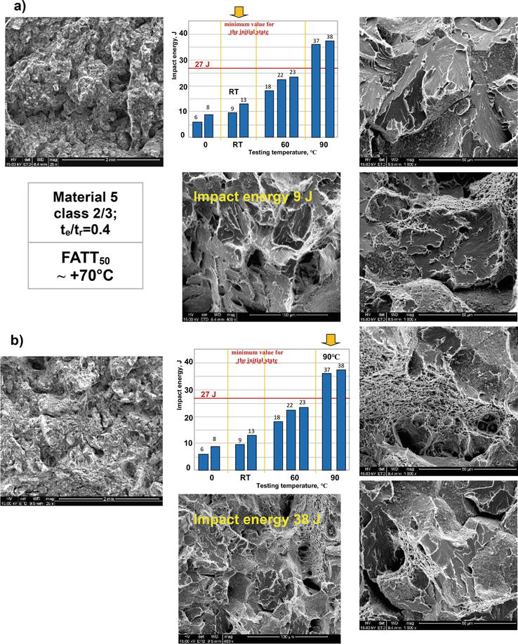
The fractography of fractures obtained on fractured impact samples for selected test temperature levels observed using a scanning electron microscope for a selected representative example, that is, material No. 5 with structure class 2/3, exhaustion degree te/tr = ⁓ 0.4) and fracture appearance transition temperature FATT50 = ⁓ +70°C, are shown in Figure 11. Figure 11a shows the images of the fracture of the impact sample fractured at room temperature (RT) with the obtained value of impact energy of 9 J. Figure 11b shows the images of the fracture of the impact sample obtained at the temperature of +90°C with the impact energy value of 38 J. At room temperature, a brittle fracture with small enclaves of a ductile fracture was obtained, while at the temperature of +90°C a mixed fracture with a predominance of a brittle fracture was obtained.
Figure 11.
Fractographic images of impact samples of the steam turbine rotor material made of Cr-Mo-V (21HMF) steel after long-term operation: a) fractured at room temperature, b) fractured at +90°C.
Short-term creep tests in accordance with the developed own procedure [1, 3] were used to determine the residual life and available residual life. Residual life ter is the time to destruction as a result of material creep after operation for the assumed parameters of further operation. On the other hand, available residual life is a part of residual life and the time up to the end of the second stage of creep teb, which is also a safe time for further operation for defined temperature and stress parameters.
The applied method of shortening the duration of the creep tests until fracture consists in accelerating the creep process by increasing the test temperature Tb significantly above the values appropriate for operation, but carried out at a constant test stress corresponding to the operational stress σb = σe = constant. Short-term creep tests were performed at constant test stress σb corresponding to operational stress σe, (σb = σbe = constant) and at a constant test temperature Tb for each test, but with different values. For each of the materials with a different degree of structure degradation, tests were carried out at several test temperature levels. They were carried out at a constant stress level σb1 = 60 MPa and σb2 = 70 MPa and at several levels of test temperature Tb in the range from 600 to 700°C.
The test results are presented in Figure 12 in the form of the dependence of the time to rupture ter on the test temperature Tb at a constant stress level corresponding to operational stress σb = σe [log tr = f(Tb) at σb = constant]. This enabled drawing a line inclined to the time axis until the destruction of ter. Residual life ter was determined by extrapolating the obtained straight line toward the lower temperature corresponding to operational temperature Te. The figures show the determined residual life ter and the residual available life teb. The available residual life was determined in accordance with the procedure in accordance with [1, 3].
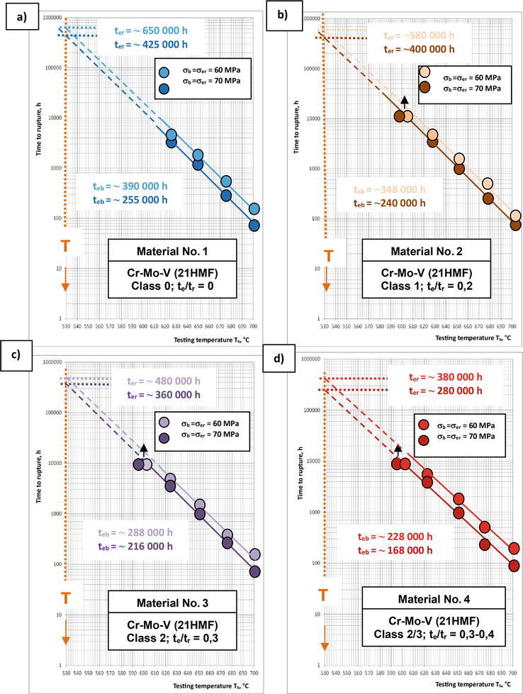
Figure 12.
Results of short-term creep tests in the form of log tr = f(Tb) at σb = constant at test temperature Tb higher than the operating temperature Te (Tb > Te) and the determined residual life ter for the operating temperature of the material of the turbine rotor components made of low-alloy steel Cr-Mo-V (21HMF) depending on the structure class and the corresponding exhaustion degree.
Residual life and residual available life decrease with the increase of the structure class and the corresponding exhaustion degree. For example, residual life ter for a material with a structure characteristic of the initial state (class 0) and at the stress level σb = σe = 60 MPa for the operating temperature Ter = 530°C is 650,0000 h, for a material after operation with a structure corresponding to class 2 and the degree of exhaustion te/tr = 0.3 is 480,000 h and the material after use with a structure corresponding to class 2/3 and the degree of exhaustion te/tr = 0.3–0.4 is 380,000 h.
Residual life for these operating parameters decreases respectively from 390,000 h for the material with the initial state structure through 288,000 h for the material with structure class 2 and te/tr = 0.3 to 228,000 h for material with structure class 2/3 and te/tr = 0.3–0.4.
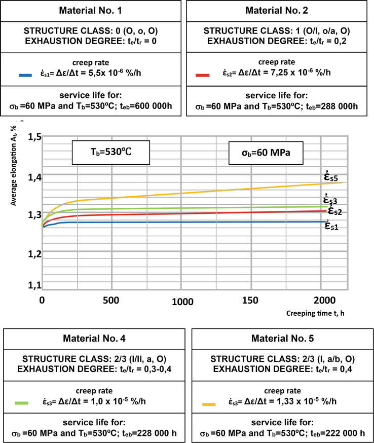
7.2 Creep rate
Creep tests with measurement of elongation during the test were carried out at a constant test temperature Tb and for test stress level σb with a constant value and duration over 2000 hours. The fragments of the creep curves obtained in these tests with a sufficiently long section of these curves in the steady state, that is. in the second creep period in the form of the dependence of the permanent deformation ε on the creep time t, allowed to determine the steady-state creep rate ἐs. Using the obtained creep curve in the form of the dependence of the value of permanent deformation Af on the creep time [(Af = f (t)] at constant test temperature Tb and test stress σb corresponding to the operational stress (Tb = Te, σb = σe), the set creep rate ἐs was determined, and from it the maximum time of safe operation teb for the assumed permissible value of permanent deformation as a result of creep. A comparison of creep curves in the form of relationship Af = f(t) w at a constant temperature Tb and constant stress σb corresponding to the operational material of turbine rotors made of Cr-Mo-V (21HMF) steel with a different, previously defined class of structure and the corresponding degree of exhaustion after operation is shown in Figure 13.
Figure 13.
Comparison of creep curves in the form of dependence Af = f(t) at a constant temperature Tb and constant stress σb corresponding to the operating material of turbine rotors made of low-alloy Cr-Mo-V (21HMF) steel with different structure class and corresponding exhaustion degree.
Determined in this way, available residual life teb at Tb = 530°C and at the stress σb = 60 MPa for the material with a structure corresponding to the initial state and class 0; (material No. 1) is 600,000 h, for material with structure class 1 (material No. 2) it is 288,000 h and for material with structure class 2/3 (material No. 4) it is 228,000 h. An increase in the structure class and the corresponding exhaustion degree for the same temperature and stress parameters results in a higher creep rate ἐs, resulting in shortening of residual available life teb.
Changes in the structure of the tested low-alloy Cr-Mo-V steel caused by long-term operation in creep conditions are the result of, on the one hand, the ‘decomposition’ of bainite, and on the other hand, the result of the development of precipitation processes related to the reduction or even disappearance of some, the formation of other precipitates, their coagulation and coalescence, often associated with other less favourable sites.
Differences in the microstructure of materials after long-term operation in relation to the microstructure of the typical initial state of the tested low-alloy ternary Cr-Mo-V steel are bainite degradation and development of the precipitation process inside its areas and development of precipitation processes on the borders and inside ferrite grains, without discontinuities and microcracks and without initiating internal creep failure processes. Their assessment was made based on the prepared classification of the state of the structure in relation to the estimated degree of exhaustion based on the above-mentioned components of its degradation processes.
The observed carbide sequences of the tested materials, based on X-ray diffraction analysis of electrolytically isolated carbide deposits, confirm the state of the microstructure estimated based on the analysis of its images observed using a scanning electron microscope.
Changes in the structure and its state defined by the class and the corresponding degree of exhaustion results in a decrease in hardness and strength properties, as well as in the impact energy to values lower than the minimum required for the initial state and shifting the fracture appearance transition temperature to a positive temperature, which reduces the ability of the tested materials to carry the required operating loads.
Creep strength measured by residual life and available residual life, which is service life and the time of further safe operation, for temperature and stress parameters of further operation based on short-term tests, decreases as the structure class and the corresponding estimated degree of exhaustion increase.
Creep strength measured by the residual available life, which is the service life and the time of further safe operation, for the temperature and stress parameters of further operation based on creep tests with the measurement of elongation during the test, decreases with the increase of the structure class and the corresponding estimated degree of exhaustion.
The significantly lower values of residual available life obtained on the basis of creep tests with measurement of elongation than those obtained on the basis of short-term tests result from the assumed limit value of permanent deformation as a result of creep, which does not correspond to the end of the second creep period as determined on the basis of short-term creep tests and is reached much before the end of the second stage of creep.
The developed characteristics of turbine rotor materials made of low-alloy ternary Cr-Mo-V steel after operation enable the assessment of the condition and estimation of the time of further safe operation using the non-destructive method of matrix and extraction replicas collected directly on the item and are used in industrial practice.
The tests carried out do not exhaust the area of necessary characteristics of the material of turbine rotors made of the tested low-alloy ternary Cr-Mo-V steel in the assessment of the condition after long-term operation. In the case of the tested materials, it is necessary to test the impact of shutdowns and start-ups on reducing the residual life on the basis of fatigue tests and cyclic creep tests and to assess the state of development of precipitation processes by revealing the places of occurrence of individual types of carbides in the microstructure based on TEM tests. These studies are in progress and their results will be presented in later publications.
References
1.Dobrzański J. Materials science interpretation of the life of steels for power plants. Open Access Library. 2011;3:1-8
2.Hernas A, Dobrzański J. Life-Time and Damage of boiler’s and turbine’s Components. Gliwice: The Silesian Technical University publishing house; 2003
3.Dobrzański J. Durability of Pressure Components of Power Units. Gliwice: The Institute for Ferrous Metalurgy publishing house; 2019
4.Dobrzański J. The procedure for determining the time of safe service beyond the design service time based on creep testing. Chapter 5. In: Creep Characteristics of Engineering Materials. London UK: Intech Open; 2019. pp. 49-68
5.Dobrzański J, Hernas A, Moskal G. Microstructural degradation in power plant steels, chapter No. 9. In: Oakey JE, editor. Power Plant Life Management and Performance Improvement. Sawston, UK: Woodhead Publishing Series in Energy: Number 23; Oxford Cambridge, Philadelphia, New Delhi: Woodhead Publishing Limited; 2011
6.Dobrzański J, Purzyńska H, Matusik M. Material tests in the assessment of condition and forecasting about further safe service of steam turbine rotors beyond the design service life. Energy. 2015;11:761-764
7.Dobrzański J, Zieliński A. Material diagnostics of components in the pressure part of steam boilers and pipelines operating under creep conditions much beyond the designed service life. Energy. 2016;4:229-233
8.Dobrzański J, Purzyńska H. Method to assess the condition of material of power units turbine rotors after a long operation in creep conditions beyond the design service life. Energy. 2019;11:745-750
9.Zieliński A. Service Life of Creep-Resistant Steels with Ferritic Matrix under Long-Term Temperature Influence (in Polish). Gliwice: Institute for Ferrous Metalurgy publishing house; 2016
10.Furmanek J, Dobrzański J. Structure and mechanical properties of 21HMF steel steam turbine rotor materials after long-term operation for a time significantly exceeding the disign time. Journal of Metallic Materials. 2021;73(2):40-55
11.Joarder A, Sarma DS, Cheruvu NS. Effect of long-term service exposure on microstructure and mechanical properties of a CrMoV steam turbine rotor steel. Metallurgical and Materials Transactions A: Physical Metallurgy and Materials Science. 1991;22:1811-1820. DOI: 10.1007/BF02646505
12.Dong J, He Y, Song G, Jung J, Shin K. Evolution of carbide morphology and composition in Cr–Mo–V steel after service exposure. Materials Technology. 2012;27(1):70-72. DOI: 10.1179/175355511X13240279340048
13.Sun Q, Li X, Li K, Cai Z, Han C, Li S, et al. Effects of long-term service on microstructure and impact toughness of theWeld metal and heat-affected zone in CrMoV steel joints. Metals. 2022;12:278. DOI: 10.3390/met12020278
Written By
Joanna Furmanek and Janusz Dobrzański
Submitted: 29 April 2023Reviewed: 17 May 2023Published: 12 December 2023