Open Access is an initiative that aims to make scientific research freely available to all. To date our community has made over 100 million downloads. It’s based on principles of collaboration, unobstructed discovery, and, most importantly, scientific progression. As PhD students, we found it difficult to access the research we needed, so we decided to create a new Open Access publisher that levels the playing field for scientists across the world. How? By making research easy to access, and puts the academic needs of the researchers before the business interests of publishers.
We are a community of more than 103,000 authors and editors from 3,291 institutions spanning 160 countries, including Nobel Prize winners and some of the world’s most-cited researchers. Publishing on IntechOpen allows authors to earn citations and find new collaborators, meaning more people see your work not only from your own field of study, but from other related fields too.
To purchase hard copies of this book, please contact the representative in India:
CBS Publishers & Distributors Pvt. Ltd.
www.cbspd.com
|
customercare@cbspd.com
An adaptive neuro-fuzzy inference system (ANFIS) is developed by combining neural-networks and fuzzy system. The ANFIS model uses the advantages possessed by the properties of neural networks and its decision making is based on fuzzy inference. The ANFIS parameters are obtained and updated by training processes. The ANFIS consists of two inputs (by Gaussian or other membership function) and an output (with constant or linear membership function). The ANFIS control is implemented by building a power system stabilizer (PSS) in power systems. The PSS function is to produce an additional stabilizing signal on the reactive mode of the generator. Training data are obtained from the systems that controlled by a conventional PSS with various conditions. The training process is carried out repeatedly until the appropriate ANFIS parameters are found. Next, the PSS based on ANFIS is applied to replace the conventional PSS on a single machine and hybrid power plants. Peak overshoot and settling time of the power systems are smaller and shorter. The ANFIS PSS makes the power system stability improve significantly in small-signal studies.
*Address all correspondence to: kadekgin@unram.ac.id
1. Introduction
Artificial intelligence (AI) includes an adaptive neuro-fuzzy inference system (ANFIS) intensively developed in recent years. So, the application of the ANFIS model penetrates some research fields. Especially in electrical engineering, some researchers implement this model on solar-cell generation to enhance performance [1], on a combination of photovoltaic and grid systems to maximize profit [2], on power management under variations of climate conditions [3], on islanding detection for low voltage micro-grid power system [4], and to reduce the harmonic in solar cell connected to distribution systems [5]. Recognizing data patterns from multiple inputs and mapping them into output precisely is the ability of the ANFIS algorithm. This ability is acquired through training sessions. During the training session, the parameters of the ANFIS are modified and updated based on training data using hybrid Aquila arithmetic [5] and artificial bee colony optimization techniques [6]. The ANFIS model is applied on control renewable energy system [7] and estimator collaborated with intelligent passivity control is used to regulate the grid-tied inverter in various operating conditions [8]. Forecasting power production in solar cell is done using the ANFIS combined with genetic algorithm [9]. The ANFIS improvement proposed to evaluate the partial discharge intensity on electrical equipment. This methods is used to search the electric insulation defects, especially for high voltage or ultra-high voltage applications [10] and to design the optimal based on the size, shape, and panel of active tower transmission system combine by biogeography-based optimization (BBO) algorithm [11]. Also, the ANFIS algorithm was applied to mitigate the frequency deviation on automatic generation control (AGC) [12] and load frequency control (LFC) [13] in multi area power systems, to minimize the error on load forecast [14], and to classify the faults type and location of a power transformer [15]. The virtual inductance tuned based on ANFIS model is used to improve small-signal stability and to control reactive power sharing in micro-grid power system [16]. The ANFIS model is used to control the fluctuation of the blade pitch in wind power plant [17]. The ANFIS is applied to control chaos and voltage collapse in power systems [18, 19], transient improvement in power systems [20] and in high voltage direct current (HVDC) transmission system [21].
2. Adaptive neuro-fuzzy inference system (ANFIS) theory
The ANFIS model bridges how to use the advantage properties of artificial neural networks (ANN) that can process data in parallel mode, recognize pattern, learn and practice in solving a problem without mathematical modeling, and build a model by using some data sets. Parameters of the ANN are adjusted and updated by training process. Furthermore, Takagi-Sugeno Tsukamoto (TSK) fuzzy inference scheme carried out to make a decision or inference. The ANFIS model consists of 5 layers, and general structure the ANFIS model shown in Figure 1. Figure 1 describes two crisp inputs (In1 and In2) and one crisp output (f). Fixed and adaptive node functions are represented by circles and squares, respectively. Membership function (MF), weight and rules locate in hidden layer. The data sets should be uniform and free from unrecognized data are used to train the ANFIS model. The MF parameters are obtained automatically through training sessions using back-propagation and least squared estimation (LSE) methods. This training process conducted until the root mean squared error (RMSE) is small enough (Exp. LSE = 10−5). The ANFIS allows only the Sugeno-type FIS. Figure 2 illustrates architecture of the ANFIS comprises antecedent and conclusions as component majority. To simplify the input–output index for networks, we use it for mapping inputs (i, j = 1,2,3) and (fij = f11, …, f33 = fk = f1, …., f9).
Figure 1.
Illustration of the ANFIS model. (a). Structure of ANFIS 2 inputs and 1 output (b). Rules matrix from input-output MF.
Figure 2.
The ANFIS model is formed after the training stage. (a) Three Gaussian MF on Input 2 (b) Surface control of input-output.
Rulek:IfxisAiandyisBj;thenfk=pkx+qky+rkE1
Rule1:IfxisA1andyisB1;thenf1=p1x+q1y+r1.
Rule2:IfxisA2andyisB1;thenf2=p2x+q2y+r2
⋮
Rule9:IfxisA3andyisB3;thenf9=p9x+q9y+r9
Ly1: Node in this layer is an adaptive node and the function is
K1,i=μAix,i=1,2,3,orK1,j=μBjy,j=1,2,3E2
Where x and y are the inputs to node i, and Ai and Bi are linguistic labels (such as low, medium, or high) concerning this node. The K1,i is the membership grade of a fuzzy set A, in this case (A1, A2, …., B3), and it is used to determine the membership grade of input A. The Gauss-type membership function for A is used in this topic and formulated as:
gxcσ=e−12x−cσ2E3
A Gauss MF is represented by two parameters c and σ. Where c and σ are the center and width of the Gauss MF, respectively.
Ly2: Node in this layer (Ly2) is a fixed node. The node and is labeled by operator (symbol) Π. The function products all of incoming signals and performs fuzzy operator AND. The output formula is as follows:
K2,k=wij=μAix×μBjy;i,j=1,2,3;k=1,2,…,9E4
Ly3: Every node in the layer Ly3 is a fixed node type and is given a label N. Ratio of the i-th rule’s firing strengths to the sum of all rule’s firing strengths are calculated in this node. Outputs of the layer Ly3 are namely normalized firing strengths, and the mathematical function written as:
Ly4: The node in this layer (Ly4) is an adaptive node and the function is expressed as follow:
K4,k=wij¯fk=wij¯pkx+qky+rk,i,j=1,2,3;k=1,2,…,9E6
Where wij¯ and (pk, qk and rk) are the normalized firing strength of Ly3 and parameters of this layer. The parameters in the layer Ly3 are referred as consequent parameters.
Ly5: Node in the layer Ly5 is a fixed node. This node is labeled by mathematical operator sigma (Σ). The overall outputs are the summation of all incoming signals computed in this node, and the function of this node is formulated as:
Multi-layer feed-forward networks are formulated by mathematical expression as follows:
Wi=μPix×μQiy;Wi=WiW1+W2;i=1,2E8
Wi=μPix×μQiy;Wi=WiW1+W2;i=1,2E9
The membership function (MF) lies between value of 0 and 1, and it is evaluated using mathematical expression as follows:
μPix=11+x−ripi−12pi−3;μPix=exp−x−ripi2biE10
Where pi, ri and bi are parameters of the membership function. Input signal that in crisp value form is transformed into fuzzy value by considering the MF. Arrangement of MF shape and fuzzy inference system (FIS) settings are carried out by trial and error method in off-line mode until a model is found that meets the requirements.
The ANFIS algorithm in this scheme is used as a power system stabilizer (PSS) in a single machine model power system. The PSS function is to generate a stability signal which is modulated in the excitation system to improve power system stability.
Suppose we have a single-machine power system that supplies the infinite bus, the diagram model is simplified and illustrated in Figure 3a. The model and parameter data are taken from [22]. The first time is to collect the data input-output for training the ANFIS model that consist of 2 inputs (rotor speed deviation (om11) and its derivative (de11)), and one output (additional stability signal, vs). The data training is collected by running the system equipped with conventional PSS in variation mode, as shown in Figure 3b. The data training is obtained in 56 data points, so this data is formed into data training format using MATLAB in matrix form with 3 × 56. Then, the training data matrix is exported to the MATLAB workspace. Next, train the ANFIS model by running MATLAB’s ‘anfisedit’ function. The training processes are done in off-line mode.
Figure 3.
Single machine for small signal stability model, (a) power system and PSS diagram block, (b), collecting data input-output for training ANFIS PSS.
Figure 4a shows that the process to import the training, testing, and checking data points from the workspace in the anfisedit tool. Also, the iteration of the training process is in 30 Epochs. Figure 4b illustrates the choice of linguistic variables: There are three linguistic variables are applied to describe each input variable (Negative, NE; Zero, ZE; and Positive, PO. Gaussian membership functions (MFs) are implemented to represent the degree of membership variable inputs. The Gaussian MF is developed by two parameters (c and σ). The c and σ parameters are defined as the center and width of the MF, respectively. First-order Takagi-Sugeno fuzzy model is chosen for simplification of its model and to gain computational efficiency. The grid partition method is applied to generate fuzzy inference system (FIS). The unknown parameters of the Gaussian MF such as width, center, and linear outputs of each rule are optimized using training data sets. All parameter’s initial values are set to zero. The optimization method used to obtain parameters is hybrid or back-propagation and least squares estimation (LSE) method(s).
Figure 4.
The ‘anfisedit’ menu to input training data and set ANFIS parameters. (a) Import the train data from workspace (b). Input-output MF parameters.
The ANFIS model formed in a few seconds during the training process. After some training stages pass, the result (ANFIS model) saves on the file with *.fis format in the MATLAB environment. The ANFIS model is ready to be embedded in the Simulink model to replace the conventional PSS in power system stability or other control system fields. This training session produces three Gaussian MFs for the Input 2 (a derivative of rotor speed deviation). This Gaussian MF illustration is depicted in Figure 2a. This training also generates an input-output mapping, where this mapping describes the relationship between the magnitude of the two input signals, and the signal magnitude generated in the control scheme. This mapping is applied to meet the output control signal, and the plant needs the control signal to improve the plant′s or system′s stability. The input-output surface control for this power system stabilizer is depicted in Figure 2b (Tables 1 and 2).
MF name
Parameter
Input 1
σ (width) × 10−4
c (center) × 10−4
Δωmf1
1.309
−4.801
Δωmf2
−1.719
Δωmf3
1.363
Input 2
dΔωmf1
1.411
−5.219
dΔωmf2
−1.895
dΔωmf3
1.429
Table 1.
Input variables: Type Gaussian; range: [−4.801 1.01] × 10−4.
MF name
Parameter
p
q
R
Vpssmf1
5.996 × 10⁻²
−6.46 × 10⁻⁴
−5.878 × 10⁻³
Vpssmf 2
−2.401 × 10⁻²
−2.582 × 10⁻²
−1.577 × 10⁻²
Vpssmf 3
3.061 × 10⁻³
3.562 × 10⁻³
1.39 × 10⁻²
Vpssmf 4
−2.202 × 10⁻²
−2.55 × 10⁻²
1.231 × 10⁻²
Vpssmf 5
8.228 × 10⁻²
7.295 × 10⁻²
−5.722 × 10⁻³
Vpssmf 6
−8.117 × 10⁻²
−2.424 × 10⁻²
−9.984 × 10⁻³
Vpssmf 7
3.911 × 10⁻³
−3.561 × 10⁻⁴
1.013
Vpssmf 8
−1.716 × 10⁻²
−2.909 × 10⁻²
1.061 × 10⁻²
Vpssmf 9
1.25 × 10⁻¹
−6.073 × 10⁻²
−1.685 × 10⁻³
Table 2.
Output variable: Type linear (orde 1); range: [−9.231 3.17] × 10−3.
4.1 ANFIS-PSS for stability improvement in a single machine
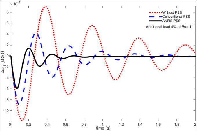
The examination of ANFIS PSS was done by adding the load disturbing on the mechanical mode of power system. Figure 5 shows the response on rotor speed deviation (Δω) of the power system for additional loading at 0.04 pu (4%). The single machine response for rotor speed deviation with additional loading (disturbance) at 0.02 and 0.04 pu (2 and 4%) is listed in Table 3. This response is used to assess the stability of the single machine. In this scenario, the machine was run without PSS, with conventional PSS, and with ANFIS-based PSS. From Table 3 and Figure 5, the system response without PSS for peak overshoot (Mp) was obtained at −5.69 × 10⁻⁴ rad/s. Moreover, the system response without PSS was un-damped and oscillated, and the settling time (tst) was more than 2 seconds (s). Meanwhile, the responses of the conventional and ANFIS PSS(s) for the peak overshoots were achieved at −3.84 × 10⁻⁴ and − 3.69 × 10⁻⁴ rad/s, respectively. The settling times were obtained at the time 1.56 and .98 s the conventional and ANFIS PSS(s), respectively. From this scenario, the ANFIS PSS is more effective in improving the stability of the single machine power system with less peak overshoot and shorter settling time for rotor speed deviation, compared to the other PSS.
Figure 5.
Improvement of rotor speed deviation using ANFIS PSS.
Additional load disturbing (%)
Without PSS
Conventional PSS
ANFIS PSS
Mp × (−10–4) (rad/s)
tst (s)
Mp × (−10–4) (rad/s)
tst (s)
Mp × (−10–4) (rad/s)
tst (s)
2
2.85
>2
1.92
1.62
1.72
.96
4
5.69
3.84
1.56
3.69
.98
Table 3.
Peak overshoot and settling time for rotor speed deviation.
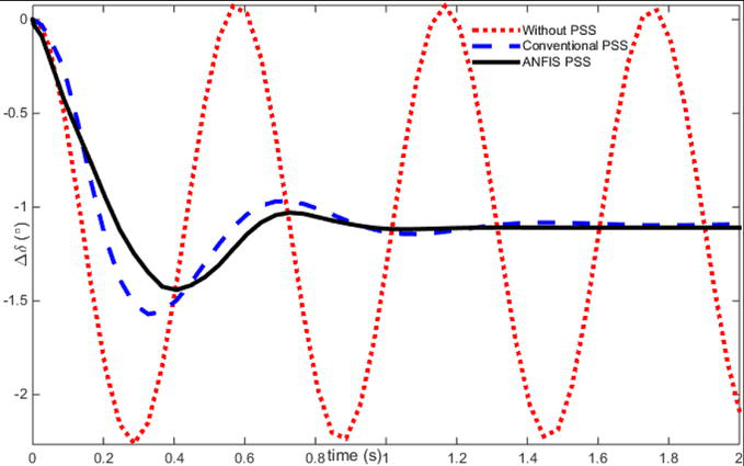
The next session is explained the response for rotor angle (Δδ) and the simulation results are shown in Figure 6 and Table 4, respectively. The peak overshoot was achieved at the values of −1.13, −.68, and − .66° for the system without the PSS, conventional PSS, and ANFIS PSS, for a disturbance at 2%. The settling time was achieved at times 1.61 and .95 s for the conventional PSS and ANFIS PSS. The rotor angle steady state was obtained at −.54 and − .57° for the system with the conventional PSS and ANFIS PSS, respectively.
Figure 6.
Enhancement of rotor angle stability for disturbance 4%.
Additional load disturbing (%)
Without PSS
Conventional PSS
ANFIS PSS
Mp × −1 (°)
tst (s)
δ × −1 (°)
Mp × −1 (°)
tst (s)
δ × −1 (°)
Mp × −1 (°)
tst (s)
δ × −1 (°)
2
1.13
>2
osc
.68
1.61
.54
.66
.95
.57
4
2.26
1.54
1.63
1.095
1.44
.96
1.1
Table 4.
Peak overshoot and settling time for rotor angle.
Figure 6 shows the rotor angle response. The peak overshoot was obtained at 2.26° for disturbance 4%, and the single machine was not equipped by the PSS. The settling time of the response was more than 2 s. It monitored that the rotor angle response is un-damped and oscillated, and this condition is unwanted in stability studies. In the single machine equipped with the conventional PSS and ANFIS PSS, the simulation results are as follows. The peak overshoot of rotor angle was obtained at the values −1.54 and − 1.44° for the conventional PSS and ANFIS PSS, respectively. The responses of the rotor angle settled rapidly, and the settling value achieved around value 1.1°.
4.2 ANFIS-PSS for stability maintain in hybrid power system
In this session, the Lombok Island Power Plant [23, 24] with a simplified model [25] is taken as an example of ANFIS power system stabilizer (PSS). The one-line diagram of the hybrid power system for small signal stability is depicted in Figure 7. The system consists of diesel power plant (DPP) and local load (L1) in Bus 1. Bus 4: Micro hydro power plant (MHPP) and load (L4). The two transformers (Tr1 and Tr4) connected from Bus 1 to Bus 5 and from Bus 4 to Bus 5, respectively. The transmission line (TL) connects the Bus 5 and Infinite bus. The PSS is installed at Generator 1 (G1) to improve stability of the whole system.
Figure 7.
The hybrid power system for small signal stability model.
The system is equipped with a conventional PSS and simulated in varied PSS parameters and load disturbing in the Generator 1 (Machine 1) to get the ANFIS model. Several data training sets were collected from this simulation. The data training sets were used to train the ANFIS PSS model. The procedure for learning the ANFIS algorithm is similar to Section 3. The result of training stage is explained as follows: The ANFIS PSS model with two inputs (omega and d_omega) and one output (Vpss) is illustrated by some diagram blocks. This model is described in Figure 8a. The inputs omega and d_omega are the rotor speed deviation of Generator 1 and its derivative, respectively. The ANFIS-based PSS output is the additional stabilizer signal. This signal is fed to the excitation system Generator 1. The membership function (MF) for d_omega input is shown in Figure 8b, where the MFs consist of 5 type-2 Gauss MFs. The 25-linguistic-rule is used to illustrate the connection of the input and output parameters in the ANFIS PSS. This rule-based is depicted in Figure 8c. Also, the input-output mapping can be implemented by input-output surface control as shown in Figure 8d.
Figure 8.
ANFIS PSS for hybrid power plant. (a) ANFIS PSS in Simulink model (b) Gauss-2 type MF for d_omega input (c). A 25-ANFIS-rule for PSS Generator 1 (d) Surface control for ANFIS PSS.
The system was disturbed by additional electrical power at 2 and 4% in Machine 1 to examine the performance of the ANFIS PSS, and the responses of respective PSS are shown Figures 9–12. The complete performances also are listed in Tables 5–8. Figure 9 shows the improvement of rotor speed deviation for the Machine 1 disturbed by 4% at the Machine 1. The response for respective PSS is compared to prove the effectiveness of the ANFIS PSS over others in this graphic.
Figure 9.
Improvement of rotor speed deviation stability using ANFIS PSS.
Figure 10.
Improvement of rotor angle stability using ANFIS PSS.
Figure 11.
Response enhancement of rotor speed stability for Machine 4 (Δω4).
Figure 12.
The ANFIS PSS to maintain rotor angle stability for Machine 4 (Δδ4).
Additional load disturbing
Without PSS
Conventional PSS
ANFIS PSS
Mp × (−10–4) (rad/s)
tst (s)
Mp × (−10–4) (rad/s)
tst (s)
Mp × (−10–4) (rad/s)
tst (s)
2
5.87
>2
4.43
1.81
3.38
1.42
4
11.76
8.85
1.98
5.91
1.47
Table 5.
Peak overshoot and settling time for machine 1 rotor speed deviation.
Additional load disturbing (%)
Without PSS
Conventional PSS
ANFIS PSS
Mp × −1 (°)
tst (s)
δ × −1 (°)
Mp × −1 (°)
tst (s)
δ × −1 (°)
Mp × −1 (°)
tst (s)
δ × −1 (°)
2
1.65
>2
.97
.92
1.63
.95
.73
1.36
.93
4
3.39
1.94
1.89
1.96
1.98
1.47
1.43
1.91
Table 6.
Peak overshoot and settling time for machine 1 rotor angle.
Additional load disturbing
Without PSS
Conventional PSS
ANFIS PSS
Mp × (−10−5) (rad/s)
tst (s)
Mp × (−10−5) (rad/s)
tst (s)
Mp × (−10−5) (rad/s)
tst (s)
2
11.12
>4
4.52
3.99
1.72
.96
4
22.35
9.04
>4
2.78
3.86
Table 7.
Peak overshoot and settling time for machine 4 rotor speed deviation.
Load disturbing (%)
Without PSS
Conventional PSS
ANFIS PSS
Mp × −1 (°)
tst (s)
δ × −1 (°)
Mp × −1 (°)
tst (s)
δ × −1 (°)
Mp × −1 (°)
tst (s)
δ × −1 (°)
2
.526
>4
.3
.31
3.52
.29
.15
3.45
.26
4
1.05
.59
.61
3.67
.59
.53
3.51
.59
Table 8.
Performance of rotor angle (Δδ4) for Machine 4.
Table 5 lists the peak overshoot for disturbing 2% was achieved at −5.87, −4.43 and − 3.38 × 10⁻⁴ rad/s, for the system without PSS, with the conventional PSS and ANFIS PSS, respectively. The settling time occurred at 1.81 and 1.42 s for the conventional PSS and ANFIS PSS. Moreover, the peak overshoot was obtained at −11.76, −8.85 and − 5.91 × 10⁻⁴ rad/s, for disturbance 4%. The system is settled at time 1.98 and 1.47 s, respectively, for the conventional PSS and ANFIS PSS.
The stability enhancement for rotor angle with the electrical load disturbing 4% is described in Figure 10. The rotor angle felt with first swing and the peak overshoot was achieved at −3.69, −1.97 and − 1.49°, for the system without PSS, with the conventional PSS and ANFIS PSS, respectively. The steady state of rotor angle was obtained at the values of −1.94, −1.94 and − 1.91°, for the system without PSS, with the conventional PSS and ANFIS PSS. The settling time was obtained at times 1.96 and 1.43 s, the conventional PSS and ANFIS PSS. This performance is depicted in Table 6.
Figure 11 shows the stability enhancement of rotor speed deviation response for the Machine 4. The peak overshoot for disturbing 4% was achieved at −22.35, −9.04 and − 2.78 × 10⁻⁵ rad/s, for the system without PSS, with the conventional PSS and ANFIS PSS, respectively. The ANFIS PSS gives better response than the other PSS(s). The peak overshoot and settling time are smaller and shorter than the others, respectively. The complete performances in this scenario are listed in Table 7. Meanwhile, the response of the rotor angle for machine 4 is shown in Figure 12. The peak overshoot for the system without PSS, with the conventional PSS and ANFIS PSS was at −22.35, −1.05, −.61 and − .53°, respectively. The steady state of rotor angle for the Machine 4 is around −.59°, for all the PSS(s) (Table 8).
The adaptive neuro fuzzy inference system (ANFIS) algorithm is developed and is used to replace the power system stabilizer (PSS) function in power system models. The ANFIS PSS function is to improve the power system stability for a small signal stability study. The ANFIS model is built using a learning method in offline mode based on training data. Some training data are obtained by simulating the power system equipped by conventional PSS with varied setting parameters and operating conditions. The ANFIS based PSS consists of two inputs (rotor speed deviation and its derivative), an output (Vpss) as additional stability signal. This signal is fed to the reactive mode of generator (machine). The ANFIS PSS is applied to improve the stability of the single machine and hybrid power system model. The ANFIS PSS simulation results are compared to the power system without PSS and conventional PSS to validate the simulation results. The ANFIS PSS gives better performance than the others. The assessment is carried out on the peak overshoot and settling time of each system. The peak overshoot of the ANFIS PSS is smaller than the peak overshoot of the other PSS. The settling time of the ANFIS PSS is shorter than the settling time of the others in all scenarios. The ANFIS as a universal estimator model and this model has been proven to maintain small-signal stability in power systems.
In this occasion the authors would like thank to “RISTEK-DIKTI” Republic of Indonesia to provide financial support through PDKN 2023 scheme to publish this book chapter. Also we would like thank to the LPPM-UNRAM to facilitate the writing of this book chapter is well done.
1.Priyadarshi N, Padmanaban S, Holm-Nielsen JB, Blaabjerg F, Bhaskar MS. An experimental estimation of hybrid ANFIS-PSO-based MPPT for PV grid integration under fluctuating sun irradiance. IEEE Systems Journal. 2020;14(1):1218-1229. DOI: 10.1109/JSYST.2019.2949083
2.Leonori S, Alessio Martino A, Mascioli FMF, Antonello Rizzi A. ANFIS microgrid energy management system synthesis by hyperplane clustering supported by neurofuzzy min–max classifier. IEEE Transactions on Emerging Topics in Computational Intelligence. 2019;3(3):193-204. DOI: 10.1109/TETCI.2018.2880815
3.Fekry HM, Eldesouky AA, Kassem AM, Abdelaziz AY. Power management strategy based on adaptive neuro fuzzy inference system for AC microgrid. IEEE Access. 2020;8:192087-192100. DOI: 10.1109/ACCESS.2020.3032705
4.Mlakić D, Member S, Baghaee HR, Nikolovski S. Transactions on smart grid a novel ANFIS-based islanding detection for inverter – Interfaced microgrids. IEEE Transactions on Smart Grid. 2018;2018:1. DOI: 10.1109/TSG.2018.2859360
5.Zahariah J et al. Hybrid aquila arithmetic optimization based ANFIS for harmonic mitigation in grid connected solar fed distributed energy systems. Electrical Power System and Research. 2024;226:109898. DOI: 10.1016/j.epsr.2023.109898
6.Padmanaban S, Priyadarshi N, Bhaskar MS, Holm-Nielsen JB, Ramachandaramurthy VK, Hossain E. A hybrid ANFIS-ABC based MPPT controller for PV system with anti-islanding grid protection. Experimental Realization. 2019;7:103377-103389. DOI: 10.1109/ACCESS.2019.2931547
7.García P, García CA, Fernández LM, Llorens F, Jurado F. ANFIS-based control of a grid-connected hybrid system integrating renewable energies, hydrogen and batteries. IEEE Transactions on Industrial Informatics. 2014;10(2):1107-1117. DOI: 10.1109/TII.2013.2290069
8.Mehrasa M, Babaie M, Zafari A, Al-Haddad K. Passivity ANFIS-based control for an intelligent compact multilevel converter. IEEE Transactions on Industrial Informatics. 2021;17(8):5141-5151. DOI: 10.1109/TII.2021.3049313
9.Semero YK, Zhang J, Zheng D. PV power forecasting using an integrated GA-PSO-ANFIS approach and Gaussian process regression based feature selection strategy. CSEE Journal of Power and Energy Systems. 2018;4(2):210-218. DOI: 10.17775/cseejpes.2016.01920
10.Wang J, Li P, Deng X, Li N, Xie X, Liu H, et al. Evaluation on partial discharge intensity of electrical equipment based on improved ANFIS and ultraviolet pulse detection technology. IEEE Access. 2019;7:126561-126570. DOI: 10.1109/ACCESS.2019.2938784
11.Hosseini N, Ghasemi MR, Dizangian B. ANFIS-based optimum design of real power transmission towers with size, shape and panel design variables using BBO algorithm. IEEE Transactions on Power Delivery. 2021;37(1):29-39. DOI: 10.1109/TPWRD.2021.3052595
12.Meseret GM, Saikia LC. Power system with the impact of HVDC links on the control system evaluation of automatic conventional neuro-fuzzy power system with impact of HVDC links on the system frequency using the conventional PID and adaptive neuro-fuzzy controller. IFAC PapersOnLine. 2022;55(1):138-143. DOI: 10.1016/j.ifacol.2022.04.023
13.Pappachen A, Peer Fathima A. Load frequency control in deregulated power system integrated with SMES-TCPS combination using ANFIS controller. International Journal of Electrical Power & Energy Systems. 2016;82:519-534. DOI: 10.1016/j.ijepes.2016.04.032
14.Ali M, Adnan M, Tariq M, Poor HV. Load forecasting through estimated parametrized based fuzzy inference system in smart grids. IEEE Transactions on Fuzzy Systems. 2020;29(1):156-165. DOI: 10.1109/TFUZZ.2020.2986982
15.Hooshmand RA, Parastegari M, Forghani Z. Adaptive neuro-fuzzy inference system approach for simultaneous diagnosis of the type and location of faults in power transformers. IEEE Electrical Insulation Magazine. 2012;28(5):32-42. DOI: 10.1109/MEI.2012.6268440
16.Pournazarian B, Sangrody R, Saeedian M, Gomis-Bellmunt O, Pouresmaeil E. Enhancing microgrid small-signal stability and reactive power sharing using ANFIS-tuned virtual inductances. IEEE Access. 2021;9:104915-104926. DOI: 10.1109/ACCESS.2021.3100248
17.Elsisi M, Tran MQ, Mahmoud K, Lehtonen M, Darwish MMF. Robust design of ANFIS-based blade pitch controller for wind energy conversion systems against wind speed fluctuations. IEEE Access. 2021;9:37894-37904. DOI: 10.1109/ACCESS.2021.3063053
18.Made Ginarsa I, Purnomo MH, Hiyama T, Soeprijanto A. Improvement of transient voltage responses using an additional PID-loop on ANFIS-based composite controller-SVC (CC-SVC) to control chaos and voltage collapse in power systems. IEEJ Transactions on Power Energy. 2011;131(10):836-848. DOI: 10.1541/ ieejpes.131.836
19.Ginarsa IM, Soeprijanto A, Purnomo MH. Controlling chaos and voltage collapse using an ANFIS-based composite controller-static var compensator in power systems. International Journal of Electrical Power & Energy Systems. 2013;46(1):79-88. DOI: 10.1016/j.ijepes.2012.10.005
20.Ginarsa IM, Nrartha IMA, Muljono AB, Sultan S, Nababan S. Strategy to reduce transient current of inverter-side on an average value model high voltage direct current using adaptive neuro-fuzzy inference system controller. International Journal of Electrical and Computer Engineering (IJECE). 2022;12(5):4790-4800. DOI: 10.11591/ijece.v12i5.pp4790-4800
21.Ginarsa IM, Muljono AB, Nrartha IMA. “Transient response improvement of direct current using supplementary control based on ANFIS for rectifier in HVDC”. International Journal of Power Electronics and Drive Systems. Dec 2020;11(4):2107–2115. DOI: 10.11591/ijpeds.v11.i4. pp2107-2115
22.Kundur P. Power System Stability and Control. New York: McGraw-Hill; 1994
23.Muljono AB, Made DI, Nrartha A. Analisis Pengaruh Unit Pembangkit Tersebar Terhadap Stabilitas Dinamis Sistem Tenaga. Anal. Pengaruh Unit Pembangkit … Agung Budi Muljono, I Made Ari N. Teknol. Elektro. 2009;8(1):1-6
24.Ginarsa IM, Nrartha IMA, Sultan S, Muljono AB, Nababan S. Perbaikan stabilitas dinamik sistem tenaga terintegrasi pembangkit listrik tenaga mikro hidro dan diesel menggunakan PSS berbasis ANFIS. Jurnal Sains Teknologi & Lingkungan. 2020;6(2):249-259. DOI: 10.29303/jstl.v6i2.197
25.Nrartha IMA, Ginarsa IM, Sultan S, Muljono AB, Warindi W. Aplikasi Fuzzy Type-2 PSS untuk Perbaikan Stabilitas Dinamik Pembangkit Listrik Tenaga Mikro Hidro dan Diesel. Jurnal Sains Teknologi & Lingkungan. 2022;7(2):185-194. DOI: 10.29303/jstl.v7i2.272
Written By
Ginarsa I. Made, Nrartha I. Made Ari, Muljono Agung Budi and Ardana I. Putu
Submitted: 08 October 2023Reviewed: 12 October 2023Published: 02 May 2024
 Open access peer-reviewed chapter