 Open access peer-reviewed chapter
Abstract
A patient’s internal anatomy can be difficult to visualize when viewed on a monitor, head-mounted display, or even when looking at an actual patient. Combining medical images (CT, MRI, US, PET) with a physical model helps recover missing anatomical context and improves situational awareness. This chapter describes an augmented reality system capable of projecting medical image information directly onto curved targets such as the human body or a mannequin. The motion of the targets and the projector are tracked using a motion capture system so that the images are adjusted in real time to match the anatomy changes in position and orientation. The augmented information can be displayed using volume rendering for realistic visualization of the internal anatomy and 3D models from segmented images. Calibration is performed on the projector and the tracking system to obtain an accurate, common coordinate system and correct visual distortions created by the fact that the projected screen (human body) is no longer a plane. The system is easily extendable to other display technology and has many potential applications, including medical education, surgical planning, and laparoscopic surgery.
Keywords
- projected augmented reality
- 3D tracking
- medical display
- image-guided surgery
- multimodal image registration
1. Introduction
It is difficult to visualize and find the structures inside the human body. Generally, imaging modalities such as CT and MR are visualized as 2D slices or 3D volumes with depth and transparency using volume rendering techniques. Unfortunately, viewing these images on a remote 2D screen in the OR without the patient as a reference leads to a loss of context, particularly during surgical procedures such as Minimally Invasive Surgery (MIS) procedures. MIS are performed through one or more small incisions, using small tubes, tiny cameras (laparoscope), and surgical instruments. Another MIS approach uses robots like the Da Vinci system [1]. The laparoscopic camera (mono or stereo) provides magnified 3D views of the surgical site and helps the surgeon operate with dexterity using laparoscopic instruments. Typically, the video from the laparoscope video is displayed on a TV screen close to the surgeon (Figure 1a). The problem with this approach is that the surgeon’s tool motion viewed in the laparoscope video is decoupled with the natural viewing direction resulting in reduced hand-eye coordination that the surgeon must compensate for with training [2]. The second way to display a laparoscopic video is to use a head-mounted display (HMD) aligned in the same direction as the laparoscope cameras (see Figure 1b). This approach improves hand-eye coordination as viewing direction is now realigned with the gaze directions. A review of HMDs in surgical procedures can be found in Refs. [3, 4]. Another possibility to bring laparoscopic video into the surgeon’s field of view is to project the video directly on the patient’s skin using a projector. In this approach, the video projector is positioned in the OR over the patient to display the laparoscopic video on the patient skin. The result is attractive and intuitive due to a direct vision of the inner cavity resembling X-ray vision (Figure 1c).
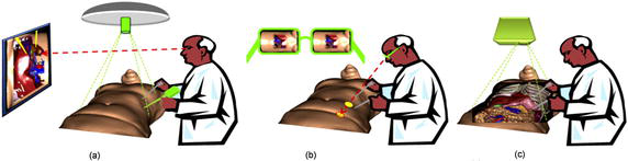
Figure 1.
Various ways to display laparoscopic video to guide MIS procedures: (a) normal screen from a video acquisition, (b) see-through display, and (c) projection display.
This chapter describes ProjectDR, a projection-based AR system that directly displays medical information and real-time sensing on a patient’s skin. In Section 1, we will review the current state of the art of Medical Augmented Reality discussing the pros and cons of very display technologies. Section 2 describes ProjectDR system configurations. Section 3 illustrates the use of ProjectDR where pre-operative models are displayed on a mannequin. We then conclude in Section 4 the pros and cons of the current system and future work.
2. Augmented reality in medicine
In the previous section, we briefly discussed three ways to display real-time laparoscopic video to improve surgeon capabilities to perform MIS procedures. In addition to real-time live data, adding pre-operative information to guide the surgeon to follow patient-specific surgical planning is possible. The combination of video and virtual augmentation is defined as Medical Augmented Reality (MAR).
Since the early experiments of Gupta
On the other hand, OST devices are based on optical see-through optical devices such as waveguides or semi-reflective mirrors that preserve the direct view of the world and simultaneously add computer-generated images into the user’s eyes. VST systems are simpler and easier to use than OST as it is much simpler to align virtual augmentation to the video stream. In OST HMD, the registration can easily be compromised as the relationship between the eye and the lens can change. In recent OST devices, eye-tracking sensing has been used to solve the problem. Because most general-purpose HMD device focal plane is usually between 2 meters to infinity, dealing with manual tasks produces perceptual difficulties such as vergence-accommodation conflict and focus rivalry [9, 10] resulting in visual fatigue and poor hand-eye coordination. Recent work by Gabbard
One solution to this problem is to develop an AR system to project virtual information directly onto the region of interest. This approach could overcome the perceptual limitations mentioned previously. Mewes
3. System configuration
The required computer hardware used for this project includes a tracking system, a projector to display the images, and a computer to run the software. The tracking used was the OptiTrack motion capture system from NaturalPoint (https://www.naturalpoint.com/). This system tracks reflective markers attached to the targets using multiple infrared cameras. The reflective markers for a target are organized into rigid bodies, where the positions of the markers are fixed relative to each other and must be visible by at least two cameras. More cameras and good positioning will result in better tracking accuracy and reduce occlusion problems. Surrounding the working area with cameras allows a full range of motion and orientation to be tracked. The required computer hardware used for this system includes a 3D tracking system for global positioning, a range sensor to digitize the skin’s curved surface, a projector to display the images, and a computer to track, process, and render images. One can see in Figure 2 ProjectDR hardware configuration.
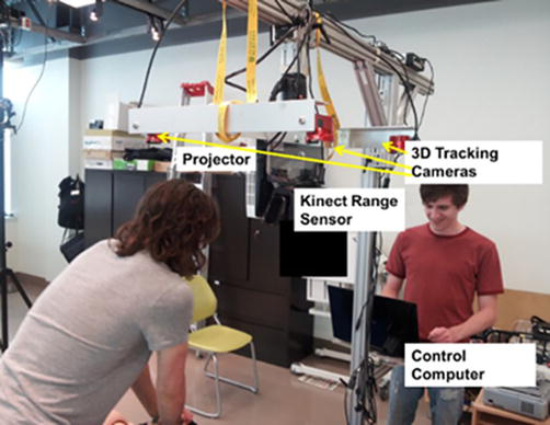
Figure 2.
ProjectDR hardware configuration.
3.1 Projector
The projector should be positioned to shine onto the desired working area. The projector can be stationary, but it is also possible to track its position with markers or to fix cameras mounted on the projector [19], allowing it to move during use. A custom mount was built so the projector could be moved by hand over a table. An Epson PowerLite 1771w projector was used to generate the image. This projector is lens-based and suffers from defocusing on very curved surfaces. This is normal, as lens-based projectors are designed to project images on planar surfaces. One can improve the defocusing effect by ensuring the projector is located directly over the region of interest by mounting it onto a gig where angles can be adjusted before the procedure. Another way to solve the problem is to use laser scanning projectors with combined RGB laser beams scanned on the skin surface using a MEMS mirror device. Because a scanning laser beam forms the image, no defocusing is present. The Nebra AnyBeam (https://www.nebra.com/) was used with success in one of our prototypes. The image quality was excellent, and no apparent defocusing was observed, even on very curved surfaces. The only issue was that many of these pico projectors suffered from a low brightness level of 150 lumens, which may not always be compatible with OR conditions.
3.2 Global tracking
Global patient tracking is performed by an OptiTrack motion capture system from NaturalPoint with a precision of 0.2 mm. Our system uses six infrared cameras to track reflective markers attached to the patient’s skin. The reflective markers are organized into rigid bodies, where the positions of the markers are fixed relative to each other and must be visible by at least two cameras. Surrounding the working area with cameras allows a full range of motion and orientation to be tracked and eventually to tack surgical tools and hand motions.
3.3 Local range sensing
Besides the global patient tracking system, a Kinect range sensor captures the shape of the skin region where the information is projected. The Kinect v2 range sensor has a field of view (FOV) of 70° × 60° and an operating range from 0.5 to 4.5 m. The ground sample distance (GSD) for the Kinect is 1.4 mm in the 0.5 m range and 12 mm at 4.5 m, which is sufficient for our application.
3.4 Registering the virtual model to patient’s markers
The augmentation model must first be registered to the patient’s markers. To do so, retroreflective markers are installed on the patient and measured using the Optitrack system. Corresponding markers must also be placed on the virtual model. Using an Iterative Closest Point algorithm [20], scaling and the rigid transformation matrix are computed to transform the virtual model in the same scale and coordinate system as the patient.
3.5 Augmented image generation
Virtual augmentations are generated by performing a real-time ray-traced of the pre-operative model. This is achieved using an NVIDIA GeForce RTX™ 30 Series GPU capable of real-time ray-traced rendering. The graphic card is powered by Ampere—NVIDIA’s 2nd gen RTX architecture with dedicated 2nd gen RT Cores. The GPU is used to ray-trace the pre-operative model from the surgeon’s viewpoint captured by a 3D tracker mounter on his head. A real-time geometric image correction is applied to the rendering to compensate for the non-planarity of the patient’s skin. A geometric warp function is applied to the rendered image so that the projected image appears geometrically correct for a given viewpoint on the patient’s skin. The algorithm is based on the one described in Ref. [21]. The algorithm used the point cloud measured by the Kinect and the projector’s intrinsic and extrinsic calibration parameters to generate this geometric warping function.
3.6 Software
The purpose of the ProjectDR software is to render different perspectives of the scene and provide control over it. ProjectDR is written in C++ with an interface in Qt and QML. The positions of the markers on the targets are streamed to ProjectDR using the NaturalPoint Motive software and NatNet SDK. The movement of the markers corresponds to the movement of any associated models in the scene and is displayed by the projector. In addition, image distortion correction is applied to the image using the information provided by the Kinect range sensor. OpenSceneGraph was used to load and render models, supporting many common model types while allowing direct control. For volume rendering, custom openGL code was written to work with OSG. This will enable ProjectDR to display volumes and polygonal models simultaneously. The software provides three main views. The “scene view” provides a zoomed-out view of all 3D models in the scene and the projector. The “model view” is for viewing and editing the position and orientation of individual models. Additional controls exist for creating a transfer function and viewing individual slices for volume rendering. The “projector view” shows what is projected onto the patient based on what a virtual camera sees in the scene from the same position and orientation as the projector. The motion tracking and projector require individual calibration, but all components must use the same coordinate system so that the virtual objects mesh with real-world targets accurately. The OptiTrack has a coordinate system that corresponds closely to the real world, can be calibrated very accurately, and is used to calibrate the other systems.
3.7 Calibration
The motion tracking and projector require individual calibration. Still, all components must use the same coordinate so that the coordinates of the virtual objects with real-world targets are accurately registered.
3.7.1 Calibrating the motion capture system
The OptiTrack system has a coordinate system, which corresponds closely to the real world and can be calibrated very accurately, so it will be used to calibrate all the other systems. The OptiTrack uses a fixed-size calibration wand that is moved around the area viewed by its six cameras to calibrate the six cameras positions, orientations, focal lengths, and lens distorsions. A right triangle with reflective markers is used to set as a reference ground plane and to set each axis’s origin and direction. The objects in ProjectDR will use the same coordinates as the OptiTrack, so the origin and offsets of the models are the same as in the OptiTrack. For example, a reflective marker placed 10 cm away from the origin will appear as a dot 10 cm away from the origin in the same direction in the virtual scene.
3.7.2 Calibrating the projector
A projector has extrinsic and intrinsic parameters to calibrate as well. The extrinsic parameters describe the position and orientation of the projector relative to the origin. This must be calculated accurately since any error will result in the models not corresponding to their physical targets. Intrinsic parameters are a mapping between the pixels of the images and what is displayed by the projector. These are the smaller distortions caused by the projector and will vary between projectors. Both sets of parameters are calculated using the OptiTrack system. A small dot displayed by the projector is effectively a vector originating at the lens and extending through the area we want to use. By projecting a series of dots on a grid and placing one of the optitrack markers in its path, we can record a series of positions in 3D space for use in a standard projector calibration algorithm (cite) to calculate the extrinsic and intrinsic parameters.
To verify the accuracy of the calibration, a virtual model of a one-by-one meter grid with 10 cm squares can be projected onto the ground plane. It was measured with a ruler and should appear on the ground with the same measurements and no visible distortions if well-calibrated. The accuracy was estimated to be 0.2 mm The projector’s location and orientation will now appear in the scene at the same location as in the real world.
3.7.3 Model registration
When a pre-operative 3D model is loaded into ProjectDR, it will be placed at the scene’s origin point. Since that is the same location as the origin for the motion tracker, its physical target can be placed at the origin and then attached to a model through ProjectDR. The target’s reflective markers are visible in the software, so the model can be moved to match the markers exactly using the model view. A model captured directly from a patient should be a close match, but scaling the models can generalize the data to work for other targets.
4. Experimental results
We used medical images from the OsiriX DICOM Image Library and a set of 3D models created from a segmented CT scan to demonstrate the system functionality. The system comprises a single computer with an Intel I7-4770 and an NVIDIA GeForce RTX™ 30 running the tracking and projection. The global motion tracking uses 12 Flex 6 cameras running at 120hz in a wide ring around the targets. An Epson PowerLite 1771w projector was chosen for its large depth-of-field and high illumination (3000 lumens). The first test was to display the vertebrae in the back (see Figure 3a) on a mannequin with three targets. This system can teach clinicians the anatomy of the spine and the anatomy surrounding it. A clinician intending to palpate the spine relies upon their touch and knowledge of physical landmarks to locate a vertebra obscured by the skin. With ProjectDR, the CT image of the patient’s spine can be displayed on the front (Figure 3b). A CT image of the thorax spine was used with a hand-crafted transfer function to show bones and some internal organs. Another application is for surgical planning. Knowing a patient’s specific anatomy is essential while planning a surgical procedure. Presenting pre-operative images of the patient gives the surgeons a greater context of the task at hand. Another application is for surgical planning. It is imperative to know a patient’s specific anatomy while planning an operation. Presenting pre-operative images of the patient gives the surgeons greater context. Many 3D models were used simultaneously for this example. The pre-operative models were segmented so it is possible to display each piece of the anatomy together or individually and move or hide them. Figure 4a shows a tumor near the heart and other important organs. Using ProjectDR, it is possible to suppress the rib cage and part of the lung, obscuring the tumor while still having a clear view of the nearby bronchus and veins (see Figure 4b).
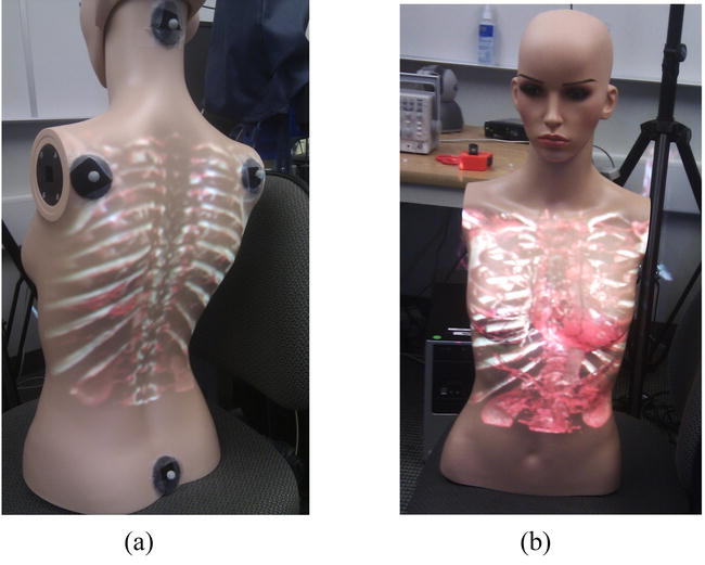
Figure 3.
Project CT data rendering on a moving test mannequin: (a) back view and (b) front view.
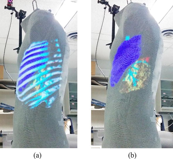
Figure 4.
Projection of 3D models of the rib cage, sections of the lungs, bronchus, and a tumor (a) Rib cage is obscuring the tumor (b) Rib cage is hidden to show location of tumor, marked in red.
5. Conclusions
This chapter describes an early prototype of the ProjectDR system that can project medical images onto a subject in real time and adapt them dynamically to changes in the patient’s position and orientation. This technology has many potential applications for surgical planning, image-guided surgeries, and medical education. One of the limitations of projection-based systems is that the perspective of the images is only correct when viewed from the point of view of the projector. For example, if a heart is projected directly onto the chest, someone looking from the side would not see the heart in the correct location as one would from the front. This could be corrected by tracking the head of the user and projecting based on their perspective. Occlusion is when an object that is not being tracked moves between the projector and the targets resulting in a shadow cast across the target or projection onto the wrong object. Occlusion is a problem for all AR systems, and research has been done with HMD that could also be applied to projection systems [22]. The color and surface texture of the targets is limiting since they will blend with the projected images. Adding a color camera to the system can correct distortions by detecting differences between the desired appearance of the images and what is visible [23]. Additionally, small projectors might not be luminous enough to project onto targets in brighter lighting conditions, but advancing projector technology could improve this [24].
Future work includes improving the system by addressing its limitations and developing new applications for the technology. The depth sensors could be used to automatically detect the initial pose and correct any errors between the models and the targets to create a more automated system. A major application would be to make models of surgical tools and track them during laparoscopic Surgery. This would show the positions of the tools inside the patient relative to anatomical structures. Collaborative environments featuring users in different locations would also be possible since virtual objects and targets could be shared between systems.
Acknowledgments
The authors would like to thank NSERC for the grand supporting this work.
References
- 1.
Longmore SK, Naik G, Gargiulo GD. Laparoscopic robotic surgery: Current perspective and future directions. Robotics. 2020; 9 :42 - 2.
Walczak DA, Pawełczak D, Piotrowski P, Trzeciak PW, Jędrzejczyk A, Pasieka Z. Video display during laparoscopy—Where should it be placed? Wideochir Inne Tech Maloinwazyjne. 2015; 10 (1):87-91 - 3.
Rahman R, Wood ME, Qian L, Price CL, Johnson AA, Osgood GM. Head-mounted display use in surgery: A systematic review. Surgical Innovation. 2020; 27 (1):88-100 - 4.
Prendergast CJ, Ryder BA, Abodeely A, Muratore CS, Crawford GP, Luks FI. Surgical performance with head-mounted displays in laparoscopic surgery. Journal of Laparoendoscopic & Advanced Surgical Techniques. Part A. 2009; 19 (Suppl 1):S237-S240 - 5.
Gupta SC, Klein SA, Barker JH, Franken RJPM, Banis JC. Introduction of new technology to clinical practice: A guide for the assessment of new VR applications. Journal of Medical Virtual Reality. 1995; 1 (1):16-20 - 6.
Pratt P, Ives M, Lawton G, Simmons J, Radev N, Spyropoulou L, et al. Through the HoloLens looking glass: Augmented reality for extremity reconstruction surgery using 3D vascular models with perforating vessels. European Journal of Radiology. Exp. 2018; 2 (1):2 - 7.
Diaz R, Yoon J, Chen R, Quinones-Hinojosa A, Wharen R, Komotar R. Real-time video-streaming to surgical loupe mounted head-up display for navigated meningioma resection. Turkish Neurosurgery. 2018; 28 (4):682-688 - 8.
Cutolo F. Letter to the editor on 'augmented reality-based navigation for computer-assisted hip resurfacing: A proof of concept study. Annals of Biomedical Engineering. 2019; 47 (11):2151-2153 - 9.
Oshima K et al. SharpView: Improved clarity of defocussed content on optical see-through head-mounted displays. In: Proc. IEEE Virtual Reality (VR) Conference. Greenville, SC, USA: IEEE; 2016. pp. 253-254 - 10.
Hua H. Enabling focus cues in head-mounted displays. Proceedings of the IEEE. 2017; 105 (5):805-824 - 11.
Gabbard JL, Mehra DG, Swan JE. Effects of AR display context switching and focal distance switching on human performance. IEEE Transactions on Visualization and Computer Graphics. 2019; 25 (6):2228-2241 - 12.
Condino S, Carbone M, Piazza R, Ferrari M, Ferrari V. Perceptual limits of optical see-through visors for augmented reality guidance of manual tasks. IEEE Transactions on Biomedical Engineering. 2020; 67 (2):411-419 - 13.
Ferrari V, Carbone M, Condino S, Cutolo F. Are augmented reality headsets in surgery a dead end? Expert Review of Medical Devices. 2019; 16 (12):999-1001 - 14.
Badiali et al. Review on augmented reality in Oral and Cranio-maxillofacial surgery: Toward surgery-specific head-up displays. IEEE Access. 2020; 8 :59015-59028 - 15.
Carbone M, Piazza R, Condino S. Commercially available head-mounted displays are unsuitable for augmented reality surgical guidance: A call for focused research for surgical applications. Surgical Innovation. 2020; 27 (3):254-255 - 16.
Mewes A, Heinrich F, Kägebein U, Hensen B, Wacker F, Hansen C. Projector-based augmented reality system for interventional visualization inside MRI scanners. International Journal of Medical Robotics and Computer Assisted Surgery. 2019; 15 (1):e1950 - 17.
Edgcumbe P, Singla R, Pratt P, Schneider C, Nguan C, Rohling R. Follow the light: Projector-based augmented reality intracorporeal system for laparoscopic surgery. Journal Medical Imaging. 2018; 5 (2):1 - 18.
Mamone V, Ferrari SC, Cutolo F. Projected augmented reality to drive osteotomy surgery: Implementation and comparison with video see-through technology. IEEE Access. 2020; 8 :169024-169035 - 19.
Ferrari V, Cutolo F. Letter to the editor: Augmented reality–guided neurosurgery. Journal of Neurosurgery. 2016; 125 (1):235-237 - 20.
Zinsser T, Schmidt J, Niemann H. A refined ICP algorithm for robust 3-D correspondence estimation. In: Proceedings 2003 International Conference on Image Processing (Cat. No.03CH37429). Barcelona, Spain: IEEE; 2003. pp. II-695 - 21.
Manevarthe B, Kalpathi R. Geometric correction for projection on non-planar surfaces using point clouds. In: ICDSC’18: Proceedings of the 12th International Conference on Distributed Smart Cameras, September 2018. ACM; 2018. pp. 1-6 - 22.
Fischer J, Bartz D, Strasser W. Occlusion handling for medical augmented reality using a volumetric phantom model. In: Proceedings of the ACM Symposium on Virtual Reality Software and Technology (VRST’04). New York, NY, USA: ACM. pp. 174-177 - 23.
Rong W. Projection-Based Spatial Augmented Reality for Interactive Visual Guidance in Surgery. [PhD Thesis]. National University of Singapore; 2013 - 24.
Maiero J, Kruijff E, Hinkenjann A, Ghinea G. Focus-plus-context techniques for picoprojection-based interaction. IEEE Transactions on Multimedia. 2017; 19 (7):1521-1530