Open Access is an initiative that aims to make scientific research freely available to all. To date our community has made over 100 million downloads. It’s based on principles of collaboration, unobstructed discovery, and, most importantly, scientific progression. As PhD students, we found it difficult to access the research we needed, so we decided to create a new Open Access publisher that levels the playing field for scientists across the world. How? By making research easy to access, and puts the academic needs of the researchers before the business interests of publishers.
We are a community of more than 103,000 authors and editors from 3,291 institutions spanning 160 countries, including Nobel Prize winners and some of the world’s most-cited researchers. Publishing on IntechOpen allows authors to earn citations and find new collaborators, meaning more people see your work not only from your own field of study, but from other related fields too.
To purchase hard copies of this book, please contact the representative in India:
CBS Publishers & Distributors Pvt. Ltd.
www.cbspd.com
|
customercare@cbspd.com
Throughout the ceramic processing cycle, it is well known that a small change in the surface energy of as-received powders can have a considerable effect on the final properties of consolidated materials. The main objective of this chapter is to describe the design and manufacture of new ceramic materials based on strontium-doped lanthanum manganites, LSM (La0.8Sr0.2MnO3) and LSM-8YTZP composites, for cathode in solid oxide fuel cells (SOFC) applications due to their excellent properties, by modifying the surface energy of the starting powder using techniques, such as Diffuse Coplanar Surface Barrier Discharge (DCSBD) and atomic layer deposition (ALD). Subsequently, in order to evaluate the activation energy and optimise the sintering behaviour of these powders, the Spark Plasma Sintering (SPS) technique will be used. SPS allows the complete densification of pieces by fast and low-energy consumption processing.
Instituto de Tecnología de Materiales (ITM), Universitat Politècnica de València, Valencia, Spain
Rut Benavente
Instituto de Tecnología de Materiales (ITM), Universitat Politècnica de València, Valencia, Spain
René M. Guillén
Instituto de Tecnología de Materiales (ITM), Universitat Politècnica de València, Valencia, Spain
María D. Salvador
Instituto de Tecnología de Materiales (ITM), Universitat Politècnica de València, Valencia, Spain
Vaclav Pouchly
Central European Institute of Technology (CEITEC), Brno, Czech Republic
Martina Ilcikova
Department of Physical Electronics, Masaryk University, Brno, Czech Republic
Richard Krumpolec
Department of Physical Electronics, Masaryk University, Brno, Czech Republic
Rodrigo Moreno
Instituto de Cerámica y Vidrio, CSIC, Madrid, Spain
*Address all correspondence to: aborrell@upv.es
1. Introduction
Strontium-doped lanthanum manganite (La0.8Sr0.2MnO3) materials have a crystal structure of the perovskite-type A-B-O3, where A and B represent the 12- and 6-coordinated metals, respectively. The La1-xSrXMnO3 (LSM) has attracted attention in recent years due to its excellent thermal, electronic and magnetic properties [1] with potential applications in magnetic sensors, readout heads for magnetic memories and as a cathode in solid oxide fuel cells (SOFC) [2].
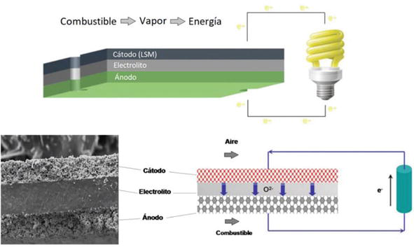
One of the most important applications of these materials is solid oxide fuel cells. The electrolyte is a ceramic oxide that is generally located in the centre of the cell (although there are exceptions such as in porous metal-supported cells) to facilitate the generation of oxygen vacancies and to transport the ionic charge between the cathode and the anode (Figure 1) [3]. The cathode and anode are electrodes where different reactions take place: oxygen is reduced to oxide ions by consuming two electrons at the cathode, and fuel is reduced by forming two electrons at the anode. The electrodes must be porous and facilitate the transport of reactants and products through the different components [4, 5].
Figure 1.
Diagram of layers forming a SOFC device.
The cathode is one of the essential components of a SOFC. The cathode materials must meet several requirements in the operating temperature of 800–1000°C: high electronic conductivity, thermal and chemical stability, catalytic activity for oxygen reduction, and a thermal expansion and coefficients of the same order as the other SOFC components [6, 7].
The use of yttria-stabilised zirconia (Y-TZP) as an electrolyte material is customarily found in the literature, being the main material used for the fabrication of solid electrochemical devices. Its use is due to the fact that this material has high conductivity and ionic stability with oxygen. It is important to emphasise that in solid oxide fuel cells with zirconia as a base material, lanthanum manganites doped with strontium are a key point for better cell efficiency. LSM materials are commonly used as cathode material due to their high electronic conductivity and fast oxygen transfer at gas–solid interfaces, combined with their thermal expansion capability and chemical compatibility with yttria-stabilised zirconia solid electrolyte [8]. The content of yttrium oxide (Y2O3) as a dopant for zirconia is a very important factor. In terms of conductivity, zirconia doped with 8–10 mol% yttria has high ionic conductivity. Moreover, in terms of structural and mechanical properties, zirconia doped with 8 mol% yttria has high flexural and impact strength [9]. Therefore, in this chapter, LSM-8YTZP composites will be investigated due to their good mechanical properties [10].
This chapter aims to study how the heating rate, the final temperature and the dwell time affect the final properties of the LSM material and the LSM-8YTZP composite densified using the Spark Plasma Sintering technology. In a second stage, a surface modification of the starting powders, both LSM and LSM-8YTZP, will be carried out using Diffuse Coplanar Surface Barrier Discharge (DCSBD) and Atomic Layer Deposition (ALD) techniques in order to identify changes in the material that may influence the sintering and, therefore, the final properties.
As raw materials, commercial La1-xSrXMnO3 (x = 0.2) powder (INFRAMAT, Advanced Materials, USA) with an average particle size of d50 = 0.25 μm, a BET-specific surface area of 2.8 m2/g and high purity commercial yttria-stabilised zirconia (YSZ) with 8 mol% Y2O3 (TZ8YS, Tosoh Corp., Japan), with an average particle size of 0.4 μm, and a BET specific surface area of 4.7 m2/g were used.
The mixture preparation was carried out after optimising the zeta potential of the LSM and 8YTZP suspensions and the rheological behaviour of the LSM-8YTZP mixture. LSM and LSM-8YTZP were prepared as concentrated suspensions in water with a solid loading of 30 vol%. The mixtures were prepared with a volume relative content of 50:50 according to a sequential addition, by first adding the deflocculant required to disperse the 8YTZP (0.5 wt.% on a dry solid basis) and then the 8YTZP powder, followed by the deflocculant required for the LSM (1.5 wt.% on a dry solid basis) before the LSM powder. The optimised slurry of the mixture was then frozen using a rotavapor (IKA, Germany) in a liquid-N2 bath and subsequently freeze-dried (Cryodos-50, Telstar, Spain) at −50°C and 0.3 mPa vacuum pressure for 24 h to sublimate the ice.
The freeze-dried powders were sintered by Spark Plasma Sintering (SPS, DR. SINTER SPS-625, FUJI, Japan), and the surface energy of this powder was also modified using low-energy techniques such as Diffuse Coplanar Surface Barrier Discharge (DCSBD) and Atomic Layer Deposition (ALD).
Spark Plasma Sintering was carried out under vacuum (5–9 Pa) using a graphite mould with a diameter of 12 mm. The temperature was measured using an optical pyrometer focused on the die wall, a constant uniaxial pressure of 15 MPa was applied above 600°C, and a dwell time of 2 min was used.
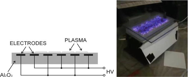
Diffuse Coplanar Surface Barrier Discharge (DCSBD) is a novel type of atmospheric-pressure plasma source developed for high-speed, large-area surface plasma treatments [11]. The plasma of DCSBD discharge is generated in a sub-millimetre thin layer above the dielectric plate. With a gradual increase of power input, the DCSBD gets visually more and more diffuse and homogeneous, though it is still composed of a high number of individual microdischarges [12, 13, 14]. Figure 2 shows a scheme of the DCSBD electrode system arrangement and a general view of the DCSBD apparatus.
Figure 2.
Cross-sectional schematics of DCSBD electrode system arrangement [15] and visual appearance of material with DCSBD apparatus.
The number of DCSBD microdischarges generated during one discharge period is very high (in the order of tens to hundreds of single microdischarges), and the generated microdischarges are distributed above a large area of approx. 20 × 8 cm2. The typical dimensions of a single microdischarge were of the order of 1 mm in length and 100 μm in diameter in the time scale of several tens of nanoseconds. The system was powered by a 14 kHz sinusoidal high voltage of up to 20 kV peak-to-peak amplitude and an input power of 400 W, supplied by a power generator. The powdered material was activated for 45 s and removed for further ceramic processing.
2.3 Atomic layer deposition (ALD)
Atomic layer deposition (ALD) is a method for depositing ultra-thin films with a wide range of applications due to its unique capabilities. This procedure can increase the efficiency of electrical devices by allowing the homogeneous deposition of conformal films with controlled thickness, even on complicated three-dimensional surfaces [16].
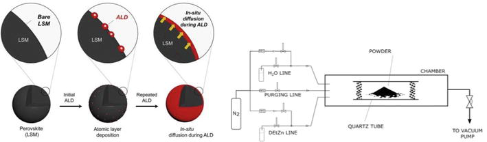
The powder was coated in a quartz tube of ID = 20 mm and length 100 mm on both sides, partially sealed by quartz wool. This tube was placed in the centre of a cylindrical deposition chamber diameter of 50 mm and a length of 450 mm. The deposition was done at a chamber pressure of 180 Pa. Pure nitrogen (99.999%) was used as a carrier and purging gas at a total flow rate of 90 sccm (standard cubic centimetres per minute). The zinc oxide coatings were deposited using Diethylzinc (DEtZn, STREM Chemicals) as a metal source and deionised water (Merck Millipore Q-water, 18.2 MΩ) as an oxygen source (Figure 3).
Figure 3.
Experimental setup of the ALD coating equipment.
Each deposition consisted of 20 ALD cycles starting with H2O pulse. One ZnO deposition cycle was defined by the following sequence: H2O pulse (10 s) → N2 purge (30 s) → DEtZn pulse (10 s) → N2 purge (30 s). Quite long pulsing and purging times were used due to the deposition of thin coatings on powders. Both DEtZn and H2O precursors were kept at room temperature. Delivery lines were heated at 60/100°C, and the temperature in the deposition chamber was 140°C. The tube with a coated powder was removed from the deposition chamber always after cooling down to 60°C.
2.4 Characterisation methods
The relative densities of specimens were determined by the Archimedes’ method following the ASTM-C-373 standard [17]. Theoretical density values of 6.57 and 6.41 g/cm3 were used for LSM and LSM-8YTZP, respectively, to estimate the relative density of the sintered specimens.
The microstructure and grain size were analysed using field emission scanning electron microscopy (FE-SEM, S4800 Hitachi, Japan). The grain size was measured using the line interception method following the ASTM E112 standard [18], with 10 interception lines being traced in each sample using Image software.
The evaluation of mechanical characteristics (hardness and Young’s modulus) was done according to the nanoindentation technique. The method used is a nanoindenter (G-200; Agilent Technologies). Tests were carried out with a Berkovich tip calibrated with silica standard and operated at a maximum depth of 2000 nm. The continuous stiffness measurement was used to determine the contact stiffness and calculate the hardness profiles and elastic modulus [19]. A matrix with 25 indentations was made for every material.
First, a Spark Plasma Sintering (SPS) study of the influence of heating rate on LSM densification was carried out. For this purpose, three heating rates were defined, i.e., 50, 100, and 200°C/min, at a final temperature of 1200°C with a dwell time of 2 min, and a constant uniaxial pressure of 15 MPa was applied above 600°C.
In Table 1, the values of average grain size and relative density corresponding to the LSM material sintered by SPS at 1200°C—2 min using different heating rates can be observed.
Material
Sintering parameters
Heating rate (°C/min)
Grain size (μm)
Relative density (%)
LSM
1200°C—2 min
50
1.75 ± 0.04
88.0 ± 0.5
100
1.77 ± 0.05
88.9 ± 0.5
200
1.85 ± 0.07
90.2 ± 0.5
Table 1.
Grain size and relative density values of LSM material sintered by SPS.
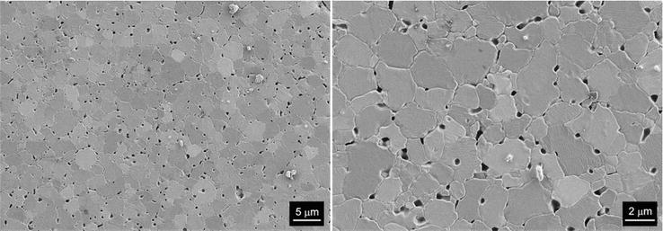
Small changes are observed with respect to relative density and grain size values. The density value above 90% is reached with a heating rate of 200°C/min. The average grain size is around 1.80 μm, approximately, as can be seen from the microstructure in Figure 4. This figure shows the FESEM microstructures, at different magnifications, of polished LSM material sintered by SPS at 1200°C with a heating rate of 200°C/min. It can be observed that large and small grains coexist. In general, all heating rates follow the same tendency, with slightly larger average grain sizes being obtained at higher heating rates, at which higher densification is achieved.
Figure 4.
Microstructure of LSM material sintered by SPS at 1200°C—2 min, heating ramp 200°C/min.
The values of hardness and Young’s modulus can be seen in Table 2. The Young’s modulus values of the material sintered at 50 and 100°C/min show similar values, but a slight increase is observed for the heating rate of 200°C/min. For hardness, an 8% increase is observed when the heating rate is increased from 50 to 200°C/min. This increase is very remarkable, as higher mechanical properties have been achieved at very high heating rates, which influences the total processing cycle of the material. Using a heating rate of 50°C/min, the complete sintering cycle reaches 16 min, and using a heating rate of 200°C/min, it only requires 8 min to complete the sintering cycle. The energy and time savings are therefore doubled.
Material
Sintering parameters
Heating rate (°C/min)
Hardness (GPa)
Young modulus (GPa)
LSM
1200°C—2 min
50
7.0 ± 0.3
108 ± 0.2
100
7.1 ± 0.3
109 ± 0.4
200
7.5 ± 0.2
120 ± 0.2
Table 2.
Hardness and young modulus values of LSM material sintered by SPS.
3.1.2 LSM powders modified by diffuse coplanar surface barrier discharge (DCSBD) and sintered by SPS
The LSM starting powders were modified by the DCSBD technique, using the parameters mentioned in Section 2.2, and then sintered by SPS at 1200°C—2 min, using the same parameters as in the previous section.
In Table 3, the values of average grain size and relative density corresponding to the LSM powders modified by DCSBD and sintered by SPS at 1200°C—2 min using different heating rates can be observed.
Material DCSBD
Sintering parameters
Heating rate (°C/min)
Grain size (μm)
Relative density (%)
LSM
1200°C—2 min
50
1.78 ± 0.04
92.7 ± 0.5
100
1.80 ± 0.03
93.1 ± 0.5
200
1.75 ± 0.05
95.1 ± 0.5
Table 3.
Grain size and relative density values of LSM powders modified by DCSBD and sintered by SPS.
By means of the DCSBD treatment, it can be identified that the density values of the material change significantly as a function of the heating rate. Density values above 95% are reached, indicating that with this treatment, the density of the final material increases significantly. These density values will have an impact on both the microstructure and the final mechanical properties. On the other hand, taking into account the grain size values in Table 1, it is observed that the materials without any treatment and with DCSBD treatment present similar values. This means that the DCSBD treatment enhances densification while maintaining the same grain sizes.
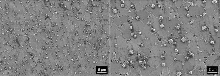
The FESEM microstructures of the DCSBD-treated sample sintered at 1200°C with a heating rate of 200°C/min, which has a value of 1.75 μm, can be seen in Figure 5 at different magnifications. Smaller particles of LSM material are observed homogeneously distributed over the entire surface. This may be due to the technique used, as the number of DCSBD microdischarges generated during a discharge period is very high (in the order of tens to hundreds of individual microdischarges), and these generated microdischarges are distributed over a large surface. This surface modification positively influences the densification of the material.
Figure 5.
Microstructure of LSM material with DCSBD treatment and SPS at 1200°C—2 min, heating ramp 200°C/min.
Figure 5 shows a small residual porosity, as the small LSM particles created are located at the grain boundary and help, on the one hand, to close the porosity and, on the other hand, have a tendency to inhibit grain growth.
The values of hardness and Young’s modulus can be seen in Table 4. The mechanical properties are also influenced by the surface treatment of the powder before sintering by SPS. Using a heating rate of 200°C/min, hardness values of 8.3 GPa are achieved. Compared to the hardness value achieved with a heating rate of 50°C/min, the improvement is 8%. These hardness values are higher than those shown in Table 2, corresponding to the non-treated LSM material. Comparing the LSM material sintered at 1200°C with a heating ramp of 200°C/min, without treatment and the one treated with DCSBD, the difference in hardness values is about 13%. The Young’s modulus values achieved using a heating ramp of 200°C/min are around 136 GPa, which represent the highest values obtained. This is in good agreement with the higher densification level.
Material DCSBD
Sintering parameters
Heating rate (°C/min)
Hardness (GPa)
Young modulus (GPa)
LSM
1200°C—2 min
50
7.7 ± 0.2
124 ± 0.2
100
7.9 ± 0.2
119 ± 0.4
200
8.3 ± 0.1
136 ± 0.3
Table 4.
Hardness and young modulus values of LSM powders modified by DCSBD and sintered by SPS.
3.1.3 LSM powders modified by atomic layer deposition (ALD) and sintered by SPS
The LSM starting powders were modified by the ALD technique, using the parameters mentioned in Section 2.3, and then sintered by SPS at 1200°C—2 min, using the same parameters as in the previous section. In Table 5, the values of average grain size and relative density corresponding to the LSM powders modified by ALD and sintered by SPS at 1200°C—2 min using different heating rates can be observed.
Material ALD
Sintering parameters
Heating rate (°C/min)
Grain size (μm)
Relative density (%)
LSM
1200°C—2 min
50
2.60 ± 0.03
87.3 ± 0.5
100
2.57 ± 0.05
88.2 ± 0.5
200
2.62 ± 0.05
90.5 ± 0.5
Table 5.
Grain size and relative density values of LSM powders modified by ALD and sintered by SPS.
The final density of the ALD surface-modified LSM sintered using different heating rates is very similar to the non-treated LSM material (Table 1). The FESEM microstructures of the ALD-treated sample sintered at 1200°C with a heating rate of 200°C/min, can be seen in Figure 6, at different magnifications.
Figure 6.
Microstructure of LSM material with ALD treatment and SPS at 1200°C—2 min, heating ramp 200°C/min.
As observed in the microphotographs, a great difference can be seen in the final grain size, which is much higher in these materials treated with the ALD technique. Porosity is observed at the grain boundaries as well as residual porosity in the interior of the grains. The average grain size in all samples is around 2.60 μm. The ZnO layer deposited by this methodology reactivates the surface of the LSM powders, leading to an exaggerated grain growth behaviour in the sintering phase. This grain growth does not help the densification of the material; therefore, the final porosity is around 10%. This will have a negative impact on the mechanical properties, as shown below.
The values of hardness and Young’s modulus can be seen in Table 6. It is observed, as with the non-treated LSM and the LSM treated with DCSBD, that as the heating ramp values are higher, the mechanical values also show an increase.
Material ALD
Sintering parameters
Heating rate (°C/min)
Hardness (GPa)
Young modulus (GPa)
LSM
1200°C—2 min
50
6.1 ± 0.2
92 ± 0.3
100
5.9 ± 0.3
109 ± 0.3
200
6.4 ± 0.1
120 ± 0.2
Table 6.
Hardness and young modulus values of LSM powders modified by ALD and sintered by SPS.
The mechanical values indicate that the LSM materials treated with the ALD technique do not lead to an improvement. Comparing the hardness values with those obtained for the non-treated LSM materials (Table 2) and those treated with DCSBD (Table 4), it can be seen that they are below 7.0 GPa.
If a comparison is carried out between the non-treated LSM materials and those treated with the different DCSBD and ALD techniques, it can be concluded that the treatment that provides the best results is the DCSBD technique. This technique provides lower residual porosity in the material and helps to inhibit grain growth, which leads to superior mechanical properties. In the following section, the influence of surface powder treatment techniques, DCSBD and ALD, on LSM-8YTZP composites will be analysed.
3.2 Study of the LSM-8YTZP powder
3.2.1 LSM-8YTZP sintered by spark plasma sintering
Spark Plasma Sintering (SPS) study of the influence of heating ramps on the LSM-8YTZP material was carried out. For this purpose, the same three heating ramps were defined, i.e., 50, 100, and 200°C/min, at a final temperature of 1200°C with a dwell time of 2 min, applying a constant uniaxial pressure of 15 MPa above 600°C. The obtained results for average grain size and relative density are shown in Table 7.
Material
Sintering parameters
Heating rate (°C/min)
Grain size (μm)
Relative density (%)
LSM-8YTZP
1200°C—2 min
50
0.30 ± 0.03
92.6 ± 0.5
100
0.36 ± 0.05
93.1 ± 0.5
200
0.40 ± 0.02
93.9 ± 0.5
Table 7.
Grain size and relative density values of LSM-8YTZP composites sintered by SPS.
It is observed that as the heating ramp is faster, higher relative density values are achieved. This indicates that rapid heating promotes the densification of these composites. As for the grain size values, all the composites sintered at different heating rates are around 0.36 μm. If these values are compared with those obtained in Table 1 for the LSM material, they are observed to be 4.5 to be lower, i.e., the 8YTZP zirconia significantly inhibits the grain growth of the LSM.
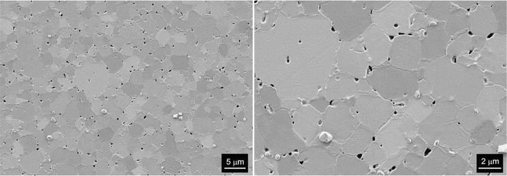
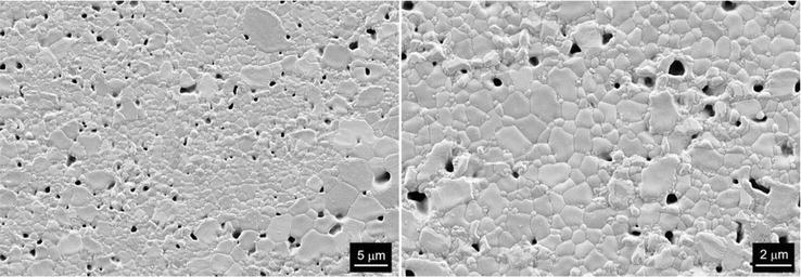
The FESEM microstructures at different magnitudes of LSM-8YTZP composites sintered at 1200°C with a heating rate of 200°C/min, as shown in Figure 7. A homogeneous microstructure is observed. The small zirconia grains are located at the grain boundary inhibiting the growth of LSM grains.
Figure 7.
Microstructure of LSM-8YTZP composite sintered by SPS at 1200°C—2 min, heating ramp 200°C/min.
The mechanical hardness and Young’s modulus values can be seen in Table 8. Hardness values above 11 GPa and Young’s modulus values around 190 GPa have been achieved using a heating ramp of 200°C/min. Moratal et al [20] achieved values around 6.0 GPa by sintering this LSM-8YTZP composite by conventional sintering at 1200°C–2 h, heating ramps of 10°C/min. In this study it was found that using the SPS technique almost twice the values of the conventional method were achieved. Another important factor to take into account is that by using SPS, whose heating rate is 200°C/min, the sintering cycle is significantly reduced. Therefore, the high added value of these composites is a very positive factor for their potential industrial applications.
Material
Sintering parameters
Heating rate (°C/min)
Hardness (GPa)
Young modulus (GPa)
LSM-8YTZP
1200°C—2 min
50
10.6 ± 0.2
179 ± 0.2
100
10.8 ± 0.2
186 ± 0.3
200
11.2 ± 0.1
190 ± 0.1
Table 8.
Hardness and young modulus values of LSM-8YTZP material sintered by SPS.
3.2.2 LSM-8YTZP powders modified by diffuse coplanar surface barrier discharge (DCSBD) and sintered by SPS
The LSM-8YTZP starting powders were modified by the DCSBD technique, using the parameters mentioned in Section 2.2, and then sintered by SPS at 1200°C–2 min, using the same parameters as described in Section 3.2.1.
Table 9 shows the values of average grain size and relative density corresponding to the LSM-8YTZP powders modified by DCSBD and sintered by SPS at 1200°C–2 min using different heating rates. As in the case of LSM powders surface-modified by the DCSBD technique, also with LSM-8YTZP powders, the density values increase to more than 95% in the composite sintered at a heating rate of 200°C/min.
Material DCSBD
Sintering parameters
Heating rate (°C/min)
Grain size (μm)
Relative density (%)
LSM-8YTZP
1200°C—2 min
50
0.92 ± 0.03
94.3 ± 0.5
100
0.94 ± 0.02
94.8 ± 0.5
200
0.89 ± 0.02
95.8 ± 0.5
Table 9.
Grain size and relative density values of LSM-8YTZP powders modified by DCSBD and sintered by SPS.
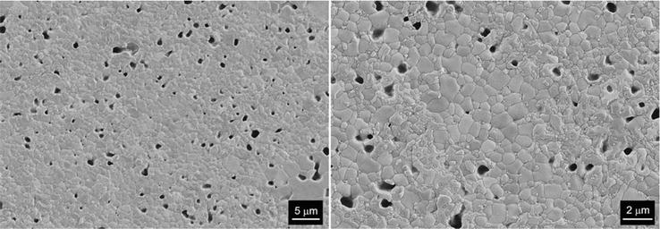
The FESEM microstructures at different magnifications of the DCSBD-treated sample sintered at 1200°C with a heating rate of 200°C/min, as shown in Figure 8.
Figure 8.
Microstructure of LSM-8YTZP composite with DCSBD treatment and SPS at 1200°C—2 min, heating ramp 200°C/min.
The grain size increases slightly in the composites with the modified powders compared to the non-modified ones, and average grain size values of around 0.90 μm are reached. A homogeneous microstructure can be observed, where besides the residual porosity, there is also grain removal due to the polishing process. Small particles of modified powder are situated at the grain boundaries, reinforcing the final material, as seen from the mechanical properties values in Table 10.
Material DCSBD
Sintering parameters
Heating rate (°C/min)
Hardness (GPa)
Young modulus (GPa)
LSM-8YTZP
1200°C—2 min
50
11.0 ± 0.3
188 ± 0.3
100
11.8 ± 0.2
196 ± 0.1
200
12.5 ± 0.2
202 ± 0.3
Table 10.
Hardness and young modulus values of LSM-8YTZP powders modified by DCSBD and sintered by SPS.
The LSM-8YTZP composite, sintered at 200°C/min, achieves hardness values of 12.5 GPa. This is very important when compared to the hardness value achieved by the DCSBD-modified LSM material sintered with the same parameters (8.3 GPa). On the one hand, it can be confirmed that the zirconia strengthens the LSM material, and the surface modification by the DCSBD technique also has a very positive effect. The dual effect of the composition and the surface modification increases by 60% both the hardness and the elastic modulus with respect to the untreated LSM material.
3.2.3 LSM-8YTZP powders modified by atomic layer deposition (ALD) and sintered by SPS
The LSM-8YTZP starting powders were modified by the ALD technique, using the parameters mentioned in Section 2.3, and then sintered by SPS at 1200°C—2 min, using the same parameters as in the previous section.
In Table 11, the values of average grain size and relative density corresponding to the LSM-8YTZP powders modified by ALD and sintered by SPS at 1200°C—2 min using different heating rates can be observed. These composites reach relative densities very close to those achieved by non-treated composites (Table 7), in the order of 93%. The grain size of the composites is similar to that achieved by the materials obtained by DCSBD treatment (Table 9).
Material ALD
Sintering parameters
Heating rate (°C/min)
Grain size (μm)
Relative density (%)
LSM-8YTZP
1200°C—2 min
50
0.90 ± 0.04
92.1 ± 0.5
100
0.92 ± 0.07
92.5 ± 0.5
200
0.91 ± 0.05
93.4 ± 0.5
Table 11.
Grain size and density values of LSM-8YTZP powders modified by ALD and sintered by SPS.
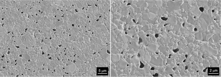
The FESEM microstructures at different magnifications of the ALD-treated sample sintered at 1200°C with a heating rate of 200°C/min, as shown in Figure 9. It can be observed that in the FESEM micrograph obtained at low magnification, there are areas where agglomerates are present, the microstructure is not homogeneous. Residual porosity locates predominantly at the grain boundaries. Zirconia particles have a grain size of 0.3–0.4 μm. These particles inhibit the grain growth of the LSM, and therefore the ALD technique does not have a strong influence on this property. The higher magnification micrograph shows some grain removal due to the polishing phase.
Figure 9.
Microstructure of LSM-8YTZP composite with ALD treatment and SPS at 1200°C—2 min, heating ramp 200°C/min.
The values of hardness and Young’s modulus can be seen in Table 12. Hardness values of over 11.0 GPa and an average Young’s modulus of around 195 GPa are achieved for all materials. These values are below those achieved when using the DCSBD technique but clearly above those of the LSM treated by ALD. The influence of the microstructure has a key role to play in the final properties.
Material ALD
Sintering parameters
Heating rate (°C/min)
Hardness (GPa)
Young modulus (GPa)
LSM-8YTZP
1200°C—2 min
50
11.2 ± 0.2
190 ± 0.3
100
11.3 ± 0.2
192 ± 0.4
200
11.8 ± 0.3
201 ± 0.2
Table 12.
Hardness and young modulus values of LSM-8YTZP powders modified by ALD and sintered by SPS.
The addition of zirconia to the LSM material improved its final properties. The LSM material, being very porous, requires higher sintering temperatures to obtain a higher densification. By adding zirconia, the open porosity value of the material is reduced, thus allowing densification at lower working temperatures. In the study carried out, it was identified that with different sintering parameters, the composite material presents different behaviours that can favour some physical properties, depending on the application for which the material is used. In the case of the composite material, when used as a fuel cell, a better interconnectivity between the particles is necessary, so the presence of zirconia is essential. On the other hand, a level of porosity is necessary for the liberation of electrons in the reaction process.
With respect to the LSM and LSM-8YTZP materials, not treated and treated with the different DCSBD and ALD techniques, it can be concluded that the materials that offer the best results are those treated with the DCSBD technique. This technique causes a lower residual porosity in the material and contributes to inhibiting grain growth, which results in superior mechanical properties. The desired improvements are less significant when using the ALD technique.
However, it is important to take into account for future work that the sintering processes in this work were carried out only by SPS, so the modification of the surface may have different results in other non-conventional sintering methods such as microwave, which could be beneficial for the final properties of the materials.
Grants PID2021-128548OB-C21 and PID2021-124521OB-100 funded by MCIN/AEI/10.13039/501100011033 and “ERDF A way of making Europe”. Grant CIGE/2021/076 funded by Generalitat Valenciana.
References
1.Zhao S, Wang Y, Zhang Y, Bai J, Zhang Y, Wang S, et al. Enhancement of the redox reactions of the La0.8Sr0.2MnO3 catalyst by surface acid etching: A simple synthesis strategy to high-performance catalysts for methane combustion. Fuel. 2023;345:128258
2.Vinchhi P, Khandla M, Chaudhary K, Pati R. Recent advances on electrolyte materials for SOFC: A review. Inorganic Chemistry Communications. 2023;152:110724
3.Kima HW, Kim HJ, Yun KS, Peck DH, Moon J, Yu JH. Electrochemical characteristics of limiting current sensors with LSM-YSZ and LSM-CGO-YSZ composite electrodes. Ceramics International. 2023;49:21521-21529
4.Li N, Sun L, Li Q, Xia T, Huo L, Zhao H. Novel and high-performance (La,Sr)MnO3 based composite cathodes for intermediate-temperature solid oxide fuel cells. Journal of the European Ceramic Society. 2023;43:5279-5287
5.Sahini MG, Lupyana SD. Perspective and control of cation interdiffusion and interface reactions in solid oxide fuel cells (SOFCs). Materials Science & Engineering B. 2023;292:116415
6.Borrell A, Salvador MD. Advanced ceramic materials sintered by microwave technology. Sintering Technology - Method and Application. Ed. Intech Open. 2018;1:3-24. DOI: 10.5772/intechopen.78831
7.Manishanma S, Dutta A. Synthesis and characterization of nickel doped LSM as possible cathode materials for LT-SOFC application. Materials Chemistry and Physics. 2023;297:127438
8.Budác D, Milos V, Carda M, Paidar M, Fuhrmann J, Bouzek K. Prediction of electrical conductivity of porous composites using a simplified Monte Carlo 3D equivalent electronic circuit network model: LSM-YSZ case study. Electrochimica Acta. 2023;457:142512
9.Gupta N, Mallik P, Lewis MH, Basu B. Improvement of toughness of Y-ZrO2: Role of dopant. Distribution. 2004;268:817-820
10.Moratal S, Guillén R, Salvador MD, Benavente R, Peñaranda-Foix FL, Moreno R, Borrell A. Comparative study of mechanical and microestructural properties of LSM ceramics obtained by E-field and H-field, AMPERE 2021 - 18th International Conference on Microwave and High Frequency Heating, Conference Paper, Code 176575
11.Čech J, Hanusová J, Sťahel P, Černák M. Diffuse coplanar surface barrier discharge in artificial air: Statistical behaviour of microdischarges. Open Chemistry. 2015;13:528-540
12.Skácelová D, Danilov V, Schäfer J, Quade A, Sťahel P, Černák M, et al. Room temperature plasma oxidation in DCSBD: A new method for preparation of silicon dioxide films at atmospheric pressure. Materials Science and Engineering B. 2013;178:651-655
13.Prysiazhnyi V, Vasina P, Panyala NR, Havel J, Cernak M. Air DCSBD plasma treatment of Al surface at atmospheric pressure. Surface and Coatings Technology. 2012;206:3011-3016
14.Pouchlý V et al. Improved microstructure of alumina ceramics prepared from DBD plasma activated powders. Journal of the European Ceramic Society. 2019;39:1297-1303
15.Černák M, Černáková L, Hudec I, Kováčik D, Zahoranová A. Diffuse Coplanar Surface Barrier Discharge and its applications for in-line processing of low-added-value materials. European Physical Journal: Applied Physics. 2009;47(2):1-6. DOI: 10.1051/epjap/2009131. hal-00497324
16.Justin Kunene T, Kwanda Tartibu L, Ukoba K, Jen T-C. Review of atomic layer deposition process, application and modeling tools. Materials Today Proceedings. 2022;62:S95-S109
17.ASTM C373–14. Standard Test Method for Water Absorption, Bulk Density, Apparent Porosity, and Apparent Specific Gravity of Fired Whiteware Products, ASTM C373–88. 88 (1999) 1–2
18.ASTM E112. Standard Test Methods for Determining Average Grain Size E112–10, ASTM E112–10. 96 (2010) 1–27
19.Oliver WC, Pharr GM. An improved technique for determining hardness and elastic modulus using load and displacement sensing indentation experiments. Journal of Materials Research. 1992;19:1564-1583
20.Moratal S, Benavente R, Salvador MD, Peñaranda-Foix FL, Moreno R, Borrell A. Microwave sintering study of strontium-doped lanthanum manganite in a single-mode microwave with electric and magnetic field at 2.45 GHz. Journal of the European Ceramic Society. 2022;42:5624-5630
Written By
Amparo Borrell, Rut Benavente, René M. Guillén, María D. Salvador, Vaclav Pouchly, Martina Ilcikova, Richard Krumpolec and Rodrigo Moreno
Submitted: 12 May 2023Reviewed: 01 June 2023Published: 28 June 2023
 Open access peer-reviewed chapter