 Open access peer-reviewed chapter
Abstract
Using semiautonomous and autonomous vehicles to perform various missions can lead to increased safety and efficiency. With all risks and limitations included, great potential exists in the integration of unmanned aerial and ground vehicles into heterogeneous robotic systems. Considering the great advances that have been made in terms of path planning, localization, control, coordinated motion, cooperative exploration, and others, such heterogeneous systems are suitable for a very wide range of tasks. In this research, the architecture that includes the ground robot as a base and the aerial robot as an extension to 3D space is examined. Such an architecture is scalable, it can be used for a wide range of missions from data collection to smart spraying. The ground robot system has been prototyped with a tracked differential drive configuration. Preliminary tests will serve as guidelines for further steps in the system development.
Keywords
- unmanned aerial vehicle
- unmanned ground vehicle
- prototype
- heterogeneous robotic system
- battery replacement mechanism
1. Introduction
The applications of mobile robots are diverse and continue to expand as technologies advance. From inspecting infrastructure to delivering goods, these robots are making a significant contribution to various industries, improving efficiency and safety while reducing costs. With the development of robotic technologies and artificial intelligence (AI), the potential for mobile robots is huge and we can expect more advanced and specialized robots in the near future. Mobile robots come in different types, including aerial [1], ground [2], and maritime robots [3], each with specific capabilities and applications. Maritime robots, including autonomous underwater vehicles (AUVs) and remotely operated vehicles (ROVs), are used for scientific research and to perform tasks such as ocean exploration, search and rescue, and underwater inspections. On the other hand, unmanned ground vehicles (UGVs) can navigate various surfaces and terrains and are suitable for applications such as delivery, inspection, and security. UGVs come in different configurations that are suitable for different types of terrain and tasks. For applications that require the robot to move over uneven and rough terrain, several configurations should be considered, with wheels [4] or tracks [5]. Aerial robots, also known as unmanned aerial vehicles (UAVs), can navigate the air and perform tasks such as aerial mapping [6], surveillance [7], and infrastructure inspection [8]. Aerial robots have been increasingly explored in recent years due to their versatility and ability to access hard-to-reach areas.
Multirotor UAVs have a number of positive features that make them a valuable tool in a variety of industries. One of the key advantages of this type of aircraft is the ability to vertically take off and land (VTOL), the possibility of stationary flight, but also their agility and maneuverability, and additionally, the ability to perform complex maneuvers. It can be said that due to the performance of the propulsion system, multirotor UAVs are very versatile and provide a unique perspective and access to areas that would otherwise be difficult or impossible to reach. They can be equipped with various sensors, cameras, and other equipment to perform a wide range of tasks. In addition, they are relatively easy to operate and require minimal training, making them available to a wide range of users. Multirotor UAVs are also cost-effective compared to traditional methods because they can perform tasks in a fraction of the time and at a fraction of the cost of manned aircraft or ground-based methods. Furthermore, electric UAVs are environmentally friendly. Their ability to perform tasks quickly and efficiently also reduces time spent on site, reducing disruption to the surrounding area. Overall, the positive properties of multirotor UAVs make them a valuable tool in a variety of cases. There is great potential for the use of aerial robots in various sectors such as inspection, agriculture, transport, and others. Numerous studies have been conducted on this topic and numerous concepts have been tested, such as in papers [9, 10, 11, 12, 13, 14, 15, 16].
Nevertheless, the high energy consumption required for multirotor motion in 3D space could result in the need for frequent battery replacement or charging, so extending the autonomy was considered. Heterogeneous robotic systems refer to the combination of different types of robots that work together to achieve a common goal. Such systems are very flexible and adaptable, which allows them to perform a wide range of tasks. In the context of ground-aerial systems, this means using aerial robots along with ground robots to perform specific tasks. Aerial-ground robotic systems offer several advantages, such as improved efficiency and increased range. For example, an aerial robot can use its ability to fly to conduct basic research such as crop monitoring, irrigation, and pest control related to the agricultural sector or to inspect turbine blades related to energy infrastructure maintenance. The combination of land and air enables the efficient execution of missions, reducing the need for human intervention and increasing safety. Overall, the use of aerial-ground robotic systems for missions involving repetitive tasks offers several advantages and is a promising approach for various industries. As technology continues to develop, we can expect more sophisticated and specialized systems that can perform increasingly complex tasks. For this purpose, heterogeneous robotic systems have been investigated in different fields and disciplines [17, 18, 19, 20, 21].
In this paper, a ground-aerial heterogeneous robotic system consisting of a UGV and a multirotor UAV is considered, where the UGV robot serves as a base station for a multirotor UAV. Such a system is scalable considering small systems that can be used for wind farm inspections or large ones that can be used in smart agriculture for, for example, smart spraying tasks. From the aspect of system development, the concept of a UGV platform that can move on uneven terrain is being considered, which consists of a landing module that enables precise take-off and landing of UAV, charging, and battery replacement. From the aspect of designing the drive module of the UGV platform, in addition to wheeled robots that can move on a wide range of terrain, from smooth surfaces to rough terrain, another configuration is a tracked robot, which is designed to move on more challenging terrains, such as rocky terrain. Tracked robots use tracks instead of wheels, which allows for better traction and stability, making them ideal for applications such as outdoor inspection and agriculture. Prototyping, assembly, and preliminary testing of the drive module of the UGV platform were carried out. In further work, the integration of the multirotor UAV and the UGV platform is planned.
2. UAV docking stations: literature review
In general, a docking station for UAVs is a multipurpose system that enables them to safely land, take off, charge, and/or replace batteries and transfers data and payload. Some docking stations, usually fixed, can even store UAVs, thus protecting them from adverse environmental conditions, such as rain or snow. The above should be autonomous in order to reduce the need for operator intervention. Therefore, docking stations for UAVs enable longer operating time for the aircraft. Docking stations can be classified according to [22]:
mobility (mobile and fixed),
battery charging method,
automatic battery replacement (swap),
storage of UAVs (yes/no),
delivery of packages or cargo for dispersal (refilling),
positioning (active and passive),
type of landing (precision, visual, etc.),
type of landing platform.
The docking station consists of multiple subsystems such as a landing platform, precision positioning mechanism, electronics, power supply, visual aid for landing, battery charging system, battery replacement system, UAV storage system, object storage system, and others. UAV docking stations must meet certain criteria to fulfill their objectives. Given that the paper considers a ground-aerial robot system, Figure 1 shows the classification of docking stations based on mobility [22].
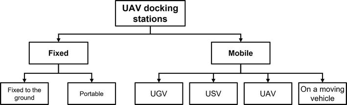
Figure 1.
UAV docking stations classification [
The landing system consists of a method of guiding the UAV that should ensure precise landing and final locking of the aerial vehicle at the intended location. Precise positioning during the landing phase is essential for a precise landing. The landing task consists of several different phases. The first phase is the access phase. Usually, systems using the global navigation satellite system (GNSS) are sufficient to access docking stations. Before touchdown, the next stage is the precise positioning of the UAV, which is crucial for a successful landing with minimal error. Touchdown is the final stage of landing. UGVs that have mounted landing systems have been presented in numerous works [23, 24, 25]. Mobile docking stations require different software solutions to precisely land the UAV on the mobile robot (UGV). The main requirement is robustness, which means the ability to land in the presence of various disturbances [26, 27, 28].
3. Ground-aerial system architecture
A heterogeneous ground-aerial system consisting of one UGV and one UAV can perform various tasks such as surveillance, reconnaissance, mapping, and inspection. The architecture of the system depends on the equipment of the system with sensors, cameras, and other devices for collecting data and performing missions. The UAV serves as the aerial component of a heterogeneous system, providing a bird’s-eye view of the area and collecting high-resolution images or video, as well as performing more complex missions. One of the features of the system is the ability to capture data from the air and send it to the UGV or base station for further processing. A UAV can also be used for planning tasks, such as identifying areas of interest or mapping the environment. The UGV serves as the ground component of the system, providing mobility and ground-level access for further data collection and mission execution. It is responsible for ground navigation using built-in sensors and cameras. UGVs can also be used to transport cargo, such as equipment or samples, to different locations. Furthermore, the paper considers a UGV that can be equipped with a battery replacement (swap) module. In general, UGVs and UAVs can be linked by wireless communication, enabling real-time data exchange and task coordination. The base station serves as the central hub of the system, providing the operator with the necessary tools and interfaces for control, mission planning, and data visualization. Figure 2 shows the reference coordinate systems of considered ground-aerial systems.
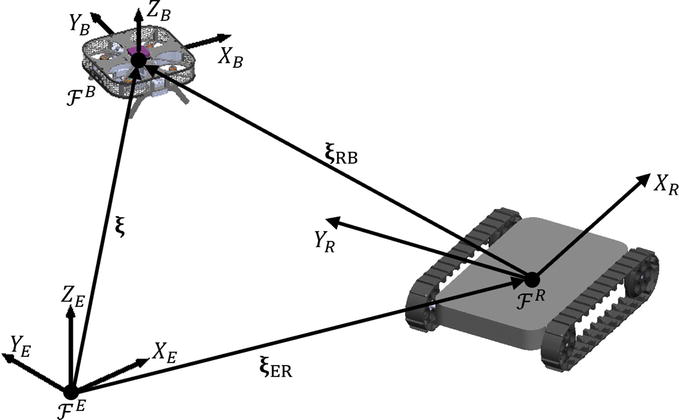
Figure 2.
Ground-aerial system reference coordinates systems.
3.1 Multirotor UAV
Given the complexity of the multirotor UAV, which is characterized as an inherently unstable, highly nonlinear, and multivariable system, it is necessary to pay special attention to the control aspect when performing simulations and experiments. These properties make multirotor UAVs challenging to control and require sophisticated algorithms and sensors to achieve stable flight. A key step in system design is the selection of control subsystem (module) components. The Cube flight controller (FC) with sensors and associated components make up the aircraft control module. For outdoor missions, the GNSS is being considered, and from the aspect of remote control, long-range R/C link with two-way communication. With the considered system, regarding the mission, we can single out two key tasks that the multirotor UAV performs during each mission. This is the take-off from the platform and the second, even more, sophisticated task, which is the precision landing of the UAV. For this purpose, the IR-LOCK sensor with associated components is considered. By choosing components based on Cube FC, it is possible to use the experimental PX4 ecosystem in combination with the MATLAB Simulink software package. This enables simple integration of simulations and experiments. Figure 3a shows a schematic quadrotor UAV mini platform that can belong to the category of so-called micro aerial vehicles (MAVs). Figure 3b shows the image transmitted in real-time from the onboard camera of the experimental quadrotor, where an example of a billboard inspection was tested.
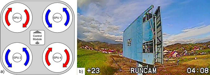
Figure 3.
Quadrotor MAV: (a) quadrotor schematic; (b) on-board camera during quadrotor testing.
3.2 UGV outdoor platform
A typical differential drive configuration consists of two electric actuators that independently move the tracks using drive elements. By changing the speed and direction of each motor, the robot can move forward, backward, turn left or right, and even rotate around its axis. This type of UGV platform is widely used in applications where better traction, easier handling, and greater stability on uneven terrain are required. Additionally, robots with a differential drive configuration are more affordable and easier to maintain compared to other drive types. During the initial phase of the development of the UGV platform, the primary goal is to ensure the scalability of the platform, while also aiming for reconfigurability. From the design aspect, the focus is on a simple integration of the basic modules of the UGV platform with the docking module, which will be equipped with a battery replacement (swap) mechanism. Figure 4 shows the topology of the UGV platform with tracks.
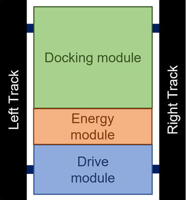
Figure 4.
UGV overall topology.
4. UGV platform prototype development and testing
Designing, prototyping, and testing of a UGV platform requires a multidisciplinary approach and a rigorous process to ensure that the final product meets the intended requirements and performs effectively. In this paper, this approach is divided into three main phases, the design phase, the prototyping phase, and the platform testing phase. In the design phase, a software package will be used for 3D modeling of the platform parts that make up the system assembly. In the prototyping phase of the parts, additive manufacturing (AM) technologies will be considered, whereby the so-called slicer tools will be used. Finally, in the third phase, a MATLAB Simulink software package will be used for simulations and experimental testing.
4.1 UGV platform design phase
Designing the UGV platform includes defining specifications and requirements, identifying necessary components and subsystems, and creating a conceptual model. Throughout the process, the design of the UGV must take into account factors such as terrain, payload, speed, and communication capabilities to ensure optimal performance. In this paper, the UGV platform is considered through four main modules, the control module, the drive module, the energy module, and the docking module. Furthermore, the design phase of the drive module of the UGV platform will be presented, and the concept of the docking module will be discussed. The UGV platform comprises a welded steel profile chassis frame onto which the UGV drive module is mounted, comprising various drive components and parts. The design of the drive module’s parts that are intended to be produced using AM technologies has been finalized. Considering the loads to which the chassis and drive elements are exposed, the design of the drive module is a challenging problem.
The drive module consists of a pair of molded tracks from the manufacturer Super Droid Robots that are driven by the drive wheels and rotate freely at the opposite end of the chassis using the auxiliary (free) wheels. The freewheel is mounted
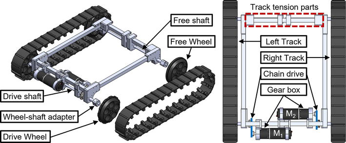
Figure 5.
UGV platform drive module assembly.
The motor’s torque is transmitted through a chain drive (transmission) to the track’s drive wheel via a sprocket with 15 teeth on the motor shaft, a roller chain (ANSI #25), and a sprocket with 25 teeth on the drive shaft. The drive shaft is connected to the chassis through bearings via frame parts, which also connect to the mount for the DC motors. In addition, in the next step, the roller for maintaining track tension and other auxiliary elements of the chassis will be integrated.
The drive module is connected to the energy and control module through a motor driver. The motor driver control circuit is linked to a control module of the UGV platform, whereas the driver’s energy circuit is connected to the LiPo battery. The battery is the central part of the energy module and considering the selected components of the UGV platform propulsion module, and the considered sizes of the multirotor UAVs, a 6-cell LiPo battery/s will be further discussed. The docking module is connected to the energy module via the electronic circuit for charging the batteries. In order to increase the simplicity, the concept of a docking module comprises a translational 3 axes mechanism. The docking mechanism is responsible for three main tasks: removing batteries from the UAV, guiding them to the charging station, and attaching them to the charger connector. To reverse the process, the mechanism retrieves the battery from the charging station, guides it to the UAV, and connects it to the UAV. The axes of the mechanism run parallel to those of the UGV platform. It is crucial to carefully consider the design of the x-axis mechanism as the battery is pulled and pushed along this axis, as shown in Figure 6, where the x-y plane of the docking mechanism is shown schematically.
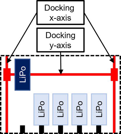
Figure 6.
Schematic representation of the concept of the mechanism for swapping batteries in the x-y plane.
4.2 UGV platform prototyping phase
The process of prototyping allows for the testing of the UGV in a simulated environment, which allows for adjustments and modifications to be made before the final product is built. In this research, two types of technologies were utilized to produce parts. The first involved using a 3-axis CNC router with a milling motor to produce parts from carbon sheet materials of various thicknesses. The second category is AM technologies, which varied depending on whether the part would be subjected to mechanical loads or not. For parts that are not mechanically loaded or are subjected to minimal loads, fused deposition modeling (FDM) technology was used, and the parts were printed using the low-cost Prusa i3 MK3 FDM printer. On the other hand, continuous fiber fabrication (CFF) technology was employed for the production of parts that would be subjected to mechanical loads. The parts were made using a Markforged Onyx Pro 3D printer applying a micro carbon fiber-filled nylon matrix material and fiberglass reinforcement material. During the prototyping phase, software tools known as slicers are used, depending on the used AM technology. The slicers read the generated stl file of one or more parts, and this step is crucial as it allows for the adjustment of the 3D print parameters, as shown in Figure 7. Once the adjustments are made, the g-code is generated, which is then executed on the 3D printing hardware. After the printing process is complete, some parts may require post-processing.
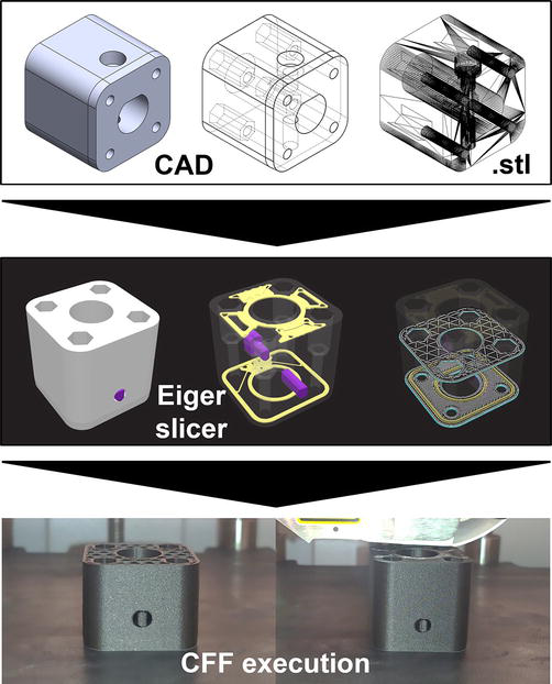
Figure 7.
Additive manufacturing main steps for prototyping parts.
4.3 UGV platform testing phase
As the UGV platform consists of modules, it is possible to conduct separate tests on each module. This expedites the development process and enables the distribution of part production. Once the frame components were manufactured, the individual modules of the platform were assembled and tested. The initial tests were conducted on the drive elements and track components of the drive module. The track was tensioned, and the rotation of the track, driven by the drive wheel, was evaluated. Next, a pair of motors and drive elements were installed, and a preliminary test of the drive configuration was performed. As the UGV platform is intended to operate in demanding terrains, Figure 8 depicts a test of the UGV platform as it crosses an obstacle.
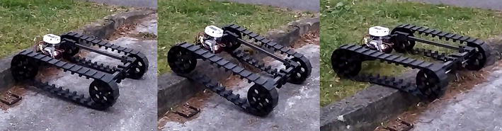
Figure 8.
Testing the UGV platform in case of crossing an obstacle.
5. Conclusion
This study aimed to explore the potential of using a UGV as a docking element in a ground-aerial robotic system. The literature review conducted on UAV docking stations gives insights into the existing technology and research in the field. The proposed ground-aerial system architecture, comprising a multirotor UAV and an outdoor UGV platform, was developed and discussed. The UGV platform prototype was developed in three phases: design, prototyping, and testing. Through this process, the UGV platform demonstrated a high level of adaptability and reliability in outdoor terrains, making it an ideal solution for a range of applications including agriculture, inspection, and search and rescue.
Acknowledgments
This research was funded by European Regional Development Fund, Operational program competitiveness and cohesion 2014–2020, as part of the call for proposals entitled “Investing in science and innovation – first call”, grant number KK.01.1.1.04.0092.
Appendices and nomenclature
three dimensional artificial intelligence autonomous underwater vehicle remotely operated vehicle unmanned ground vehicle unmanned aerial vehicle vertically take off and land flight controller global navigation satellite system remote control micro aerial vehicle additive manufacturing lithium-polymer fused deposition modeling continuous fiber fabrication
References
- 1.
Ruggiero F, Lippiello V, Ollero A. Aerial manipulation: A literature review. IEEE Robotics and Automation Letters. 2018; 3 (3):1957-1964. DOI: 10.1109/LRA.2018.2808541 - 2.
Ni J, Hu J, Xiang C. A review for design and dynamics control of unmanned ground vehicle. Proceedings of the Institution of Mechanical Engineers, Part D: Journal of Automobile Engineering. 2021; 235 (4):1084-1100. DOI: 10.1177/0954407020912097 - 3.
Matos A, Silva E, Almeida J, Martins A, Ferreira H, Ferreira B, et al. Unmanned maritime Systems for Search and Rescue [Internet]. In: Search and Rescue Robotics - from Theory to Practice. London: InTech; 2017. Available from:. DOI: 10.5772/intechopen.69492 - 4.
De Luca A, Oriolo G, Vendittelli M. Control of wheeled Mobile robots: An experimental overview. In: Nicosia S, Siciliano B, Bicchi A, Valigi P, editors. Ramsete. Lecture Notes in Control and Information Sciences. Vol. 270. Berlin, Heidelberg: Springer; 2001. DOI: 10.1007/3-540-45000-9_8 - 5.
Bruzzone L, Nodehi SE, Fanghella P. Tracked locomotion systems for ground mobile robots: A review. Machines. 2022; 10 :648. DOI: 10.3390/machines10080648 - 6.
Nex F, Remondino F. UAV for 3D mapping applications: A review. Applied Geomatics. 2014; 6 :1-15. DOI: 10.1007/s12518-013-0120-x - 7.
Motlagh NH, Bagaa M, Taleb T. UAV-based IoT platform: A crowd surveillance use case. IEEE Communications Magazine. 2017; 55 (2):128-134. DOI: 10.1109/MCOM.2017.1600587CM - 8.
Palacios AT, Cordero JM, Bello MR, Palacios ET, González JL. New applications of 3D SLAM on risk management using unmanned aerial vehicles in the construction industry. In: Dekoulis G, editor. Drones-Applications. London: IntechOpen; 2018. pp. 97-118. DOI: 10.5772/intechopen.73325 - 9.
Stanković M, Mirza MM, Karabiyik U. UAV forensics: DJI mini 2 case study. Drones. 2021; 5 :49. DOI: 10.3390/drones5020049 - 10.
Yuan C, Liu Z, Zhang Y. Aerial images-based Forest fire detection for firefighting using optical remote sensing techniques and unmanned aerial vehicles. Journal of Intelligent & Robotic Systems. 2017; 88 :635-654. DOI: 10.1007/s10846-016-0464-7 - 11.
Jung S, Jo Y, Kim YJ. Flight time estimation for continuous surveillance missions using a multirotor UAV. Energies. 2019; 12 :867. DOI: 10.3390/en12050867 - 12.
Kotarski D, Piljek P, Pranjić M, Grlj CG, Kasać J. A modular multirotor unmanned aerial vehicle design approach for development of an engineering education platform. Sensors. 2021; 21 :2737. DOI: 10.3390/s21082737 - 13.
Li M, Shamshiri RR, Schirrmann M, Weltzien C, Shafian S, Laursen MS. UAV oblique imagery with an adaptive micro-terrain model for estimation of leaf area index and height of maize canopy from 3D point clouds. Remote Sensing. 2022; 14 (3):585. DOI: 10.3390/rs14030585 - 14.
DJI Agras T40. Available from: https://www.dji.com/hr/t40?site=ag&from=nav [Accessed: 2023-02-22] - 15.
Agronator Homepage. Available from: https://agronator.de/ [Accessed: 2023-02-22] - 16.
Kotarski D, Piljek P, Kasać J. Design considerations for autonomous cargo transportation multirotor UAVs. In: Găiceanu M, editor. Self-Driving Vehicles and Enabling Technologies. London: IntechOpen; 2021. DOI: 10.5772/intechopen.95060 - 17.
Hood S, Benson K, Hamod P, Madison D, O’Kane JM, Rekleitis I. Bird’s eye view: Cooperative exploration by UGV and UAV. In: 2017 International Conference on Unmanned Aircraft Systems (ICUAS). Miami, FL, USA; 2017. pp. 247-255. DOI: 10.1109/ICUAS.2017.7991513 - 18.
Cantieri A, Ferraz M, Szekir G, Antônio Teixeira M, Lima J, Schneider Oliveira A, et al. Cooperative UAV–UGV autonomous power pylon inspection: An investigation of cooperative outdoor vehicle positioning architecture. Sensors. 2020; 20 (21):6384:1-6384:22. DOI: 10.3390/s20216384 - 19.
Asadi K, Suresh AK, Ender A, Gotad S, Maniyar S, Anand S, et al. An integrated UGV-UAV system for construction site data collection. Automation in Construction. 2020; 112 :103068:1-103068:23. DOI: 10.1016/j.autcon.2019.103068 - 20.
Vu Q , Raković M, Delic V, Ronzhin A. Trends in Development of UAV-UGV Cooperation Approaches in Precision Agriculture. In: Ronzhin A, Rigoll G, Meshcheryakov R, editors. Interactive Collaborative Robotics. ICR 2018. Vol. 11097. Lecture Notes in Computer Science. Cham: Springer; 2018. DOI: 10.1007/978-3-319-99582-3_22 - 21.
Arbanas B, Ivanovic A, Car M, Orsag M, Petrovic T, Bogdan S. Decentralized planning and control for UAV–UGV cooperative teams. Autonomous Robots. 2018; 42 :1601-1618. DOI: 10.1007/s10514-018-9712-y - 22.
Grlj CG, Krznar N, Pranjić M. A decade of UAV docking stations: A brief overview of Mobile and fixed landing platforms. Drones. 2022; 6 :17. DOI: 10.3390/drones6010017 - 23.
Narváez E, Ravankar AA, Ravankar A, Emaru T, Kobayashi Y. Autonomous VTOL-UAV docking system for heterogeneous multirobot team. IEEE Transactions on Instrumentation and Measurement. 2021; 70 :1-18 - 24.
Niu G, Yang Q , Gao Y, Pun MO. Vision-based autonomous landing for unmanned aerial and Mobile ground vehicles cooperative systems. IEEE Robotics and Automation Letters. 2021; 7 (3):6234-6241. DOI: 10.1109/LRA.2021.3101882 - 25.
Wu N, Chacon C, Hakl Z, Petty K, Smith D. Design and implementation of an unmanned aerial and ground vehicle recharging system. In: Proceedings of the 2019 IEEE National Aerospace and Electronics Conference (NAECON), Dayton, OH, USA. 15-19 July 2019. pp. 163-168 - 26.
Paris A, Lopez BT, How JP. Dynamic landing of an autonomous quadrotor on a moving platform in turbulent wind conditions. In: Proceedings of the 2020 IEEE International Conference on Robotics and Automation (ICRA), Paris, France. 31 May–31 August 2020. pp. 9577-9583 - 27.
Polvara R, Sharma S, Wan J, Manning A, Sutton R. Vision-based autonomous landing of a quadrotor on the perturbed deck of an unmanned surface vehicle. Drones. 2018; 2 :15 - 28.
Feng Y, Zhang C, Baek S, Rawashdeh S, Mohammadi A. Autonomous landing of a UAV on a moving platform using model predictive control. Drones. 2018; 2 :34