Open Access is an initiative that aims to make scientific research freely available to all. To date our community has made over 100 million downloads. It’s based on principles of collaboration, unobstructed discovery, and, most importantly, scientific progression. As PhD students, we found it difficult to access the research we needed, so we decided to create a new Open Access publisher that levels the playing field for scientists across the world. How? By making research easy to access, and puts the academic needs of the researchers before the business interests of publishers.
We are a community of more than 103,000 authors and editors from 3,291 institutions spanning 160 countries, including Nobel Prize winners and some of the world’s most-cited researchers. Publishing on IntechOpen allows authors to earn citations and find new collaborators, meaning more people see your work not only from your own field of study, but from other related fields too.
To purchase hard copies of this book, please contact the representative in India:
CBS Publishers & Distributors Pvt. Ltd.
www.cbspd.com
|
customercare@cbspd.com
Confined transverse reinforcements play important roles in improving the strength and ductility of reinforced concrete columns so that this fact is mentioned in most design codes. Chloride corrosion of such reinforcements has seriously become a growing challenge for the durability of structures leading to reductions in the capacity of reinforced concrete structures and their lifetime. Because the transverse reinforcements have small concrete covers and close to free surfaces, the corrosion in these rebars occurs earlier and more severe than longitudinal reinforcements. Reductions in confinement, deformation capacity, and ductility of reinforced concrete structures are the major consequences of corrosion. Therefore, the main objective of this article is to investigate different reinforced concrete columns under diverse corrosion levels.
Civil Engineering Department, Applied Science Center of Khorasan Razavi Municipalities, Mashhad, Iran
*Address all correspondence to: goharrokhi.ali@gmail.com
1. Introduction
Columns are one of the main critical elements of a civil structure that play vital roles in bearing capacity of various structures. For this reason, the regulations and design codes contain strict rules such important elements. According to studies, the failure of reinforced concrete columns and damage to columns caused by earthquake loads can be classified as follows [1]:
Failure caused by reciprocating bending moment and low shear due to high axial pressure, which usually occurs in slender columns according to following equation:
α=MVh=L2h>3.5E1
Failure caused by reciprocating shear and low bending moment under high axial pressure, which usually occurs in short columns according to following equation:
α=MVh=L2h<3.5E2
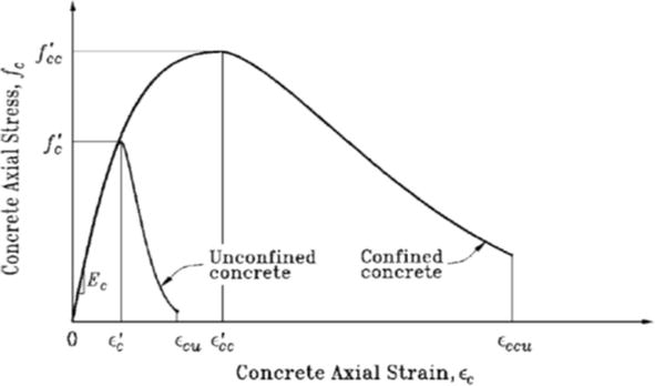
In Eqs. (1) and (2), M, V, h, and L refer to the bending moment, shear load, depth, and height of the column, respectively. Accordingly, the axial force is an important parameter in relation to the failure of concrete columns. One of the effective approaches to improving the axial strength as well as the ductility of reinforced concrete columns is their confinement using transverse reinforcements. The confinement limits the concrete lateral expansion and crack growth. Increases in the concrete strength and strain in the paste behavior areas are two main influences of the concrete confinement. This phenomenon leads to a decrease in the slope of the second part of the concrete strain–stress curve (its descending part) and an increase in the strain of the final stage. In this way, the area under the concrete stress–strain, which is equivalent to energy absorption, increases, in which case the ductility of the section of interest increases as well. For better understanding, Figure 1 shows the effect of confinement on the stress–strain curve.
Figure 1.
The effect of confinement on the stress–strain curve [2].
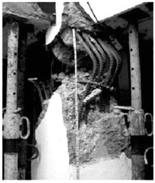
Building codes have set requirements for satisfying the behavior of columns during an earthquake through the amount and condition of the transverse reinforcement distribution. The failure of a column specimen due to large distances of transverse reinforcements is shown in Figure 2. Column failure in the previous earthquakes indicates that most of the reinforced concrete buildings were severely vulnerable to earthquakes stemming from the lack of confinement, large distances of transverse reinforcements, and other inappropriate details.
Figure 2.
The severe failure in the column due to large distances of transverse reinforcements [3].
To ensure adequate ductility of reinforced concrete columns that are subjected to seismic load, ACI 318–14 building code has set the following criteria as the minimum amount of transverse reinforcements [4]. On this basis, Eqs. (3) and (4) present the minimum ratios of transverse reinforcements needed for spirals and stirrups:
ρs≥max0.45AgACh−1fcfyt0.12fcfytE3
Ashsbc≥max0.3AgACh−1fcfyt0.09fcfytE4
where Ag, Ach, and Ash are the cross sections of the concrete specimen, confined concrete core, and the transverse reinforcements, respectively. Moreover, fc and fyt represent the compressive strength of concrete and the yield stress of the transverse reinforcement, respectively. Finally, s and bc denote the distance of the transverse reinforcements and the width of the confined concrete core, respectively. It is worth remaking that the fundamental principles of Eqs. (3) and (4) are based on the fact that the concrete column can preserve its strength after separating the concrete cover.
Corrosion of the transverse reinforcements is one of the important factors that not only reduces the bearing capacity but also may change the state of failure owing to the reduction of ductility. Therefore, the behavior of reinforced concrete columns affected by corrosion may be different from the original design. In this case, a full investigation of the effects of the corrosion of transverse reinforcements on the bearing capacity of reinforced concrete columns is of paramount importance. Despite some rules in building codes for decreasing the impact of corrosion on structures including reinforced concrete columns, there is not any formulation to estimate the axial strength of the corroded elements. This formulation allows civil engineers to evaluate the performance of structures and determine the axial capacity of columns under any condition and any degree of corrosion.
On the other hand, a better understanding of the effect of corrosion on the column performance helps owners and operators of reinforced concrete structures to reinforce damaged columns with a more open vision and careful strategic planning. In this chapter, one attempts to investigate the amount of reduction in bearing capacity of the axial structural elements due to the corrosion of transverse reinforcements.
A review of experimental studies on the reinforced concrete elements indicates that the corrosion of transverse reinforcements affects the behavior of those elements [5, 6, 7, 8, 9]. Shayanfar et al. [10] investigated the reduction of the compressive strength of reinforced concrete specimens under different degrees of corrosion. They subjected cubic specimens with different ratios of water-to-cement (w/c) under accelerated corrosion and then measured their compressive strength. Moreover, they proposed a formulation for the reduced compressive strength caused by corrosion. Ghanoni Bagha et al. [11] examined the reduction of compressive strength due to corrosion in their self-compacting concrete specimens using mineral admixtures. They concluded that the compressive strength of the concrete decreases by about 20% when the crack width increases by about 1 mm representing 7–12% corrosion in the reinforcements. Ahmadi et al. [12] evaluated the influence of the corrosion of transverse reinforcements on reducing the compressive strength of concrete confined by spirals. They corroded standard cylindrical specimens reinforced by spirals under the accelerated corrosion technique. The test variables included the corrosion percentage, spiral diameter, spiral pitch, and confined core diameter (concrete cover). Their experimental results demonstrated that the corrosion up to 2.5% affects reducing the confined strength. Moreover, it was observed that small spirals are less sensitive to correction. Goharrokhi et al. [13] investigated the reduction of the concrete compressive strength confined by corroded stirrups. In their experimental study, cubic reinforced concrete specimens with different diameters and spacing distances were subjected to various corrosion degrees. They showed that the reduction of the compressive strength depends on both the corrosion percentage and the stirrup diameter, for which they derived a formulation.
3. Effect of the transverse reinforcement corrosion on the axial strength of reinforced concrete elements
Ahmadi et al. [12] and Goharrokhi et al. [13] proposed Eq. (5) to calculate the compressive strength of the reinforced concrete elements using corroded transverse reinforcements:
fcc−corr=1−λfccE5
where fcc is the compressive strength of the unreinforced reinforced concrete element and fcc-corr denotes the compressive strength of the reinforced concrete element with corroded transverse reinforcements. Moreover, λ is the parameter for reducing the compressive strength due to corrosion of transverse reinforcements. Figure 3 shows the fracture mechanism of the reinforced specimens with corroded spirals.
Figure 3.
The fracture mechanism of the corroded reinforced cylindrical specimens [12].
Ahmadi et al. [12] constructed cylindrical reinforced concrete specimens using spirals of the size (diameter) of 4 and 6 mm to investigate the changes in the compressive strength against different degrees of corrosion as can be seen in Figure 4. They expressed logarithmical formulations between the reduced compressive strength and corrosion percentage of transverse reinforcements (Cw) as follows:
Figure 4.
Changes in the compressive strength against the corrosion degrees of under different spiral diameters [12].
λ=13.3ln1+CwE6
λ=11.5ln1+0.15CwE7
Additionally, Goharrokhi et al. [13] evaluated the changes in the concrete compressive strength against different corrosion degrees for rectangular cube specimens with 4 and 6 mm diameters as can be observed in Figures 5 and 6. They proposed the following equations for the specimens of the diameters of 4 and 6 mm, respectively:
Figure 5.
The fracture mechanism of the corroded reinforced rectangular specimens [13].
Figure 6.
Changes in the compressive strength against various corrosion degrees for different stirrup diameters [13].
4. Investigation of the concrete columns with corroded transverse reinforcement
In this section, reinforced concrete columns are investigated to evaluate the reduction of the axial strength caused by the corrosion of the transverse reinforcements. For this aim, columns with circular and rectangular cross sections were selected and the problem of interest was evaluated by using the proposed formulations by Ahmadi et al. [12] and Goharrokhi et al. [13]. The circular columns, which were reinforced and evaluated by fiber reinforced polymer (FRP), include the height of 1.5 m and the diameter of 300 mm [14, 15]. In this regard, the spirals with the diameters of 4 and 6 mm placed at the intervals of 50 and 25 mm with the concrete cover were used to reinforce these columns as shown in Figure 7(a). The rectangular columns evaluated by Regine and Sebastian [16] consist of the cross section of 140×140 mm and the height of 2 m. In these elements, four longitudinal reinforcements of the diameter of 8 mm were connected by the stirrups of the diameters of 4 and 6 mm with the intervals of 50 and 25 mm as can be observed in Figure 7(b). The columns are named C-a-b and S-a-b, where C and S represent the circular and rectangular columns, while a and b refer to the diameter and distance of the transverse reinforcements, respectively. The characteristics of the columns as well as their strength values in the non-reinforced states are given in Table 1, in which fc0 and fc denote the strength variables of the cylindrical specimen and the non-reinforced column, respectively.
Figure 7.
The details of the axial elements: (a) the circular columns [14, 15] and (b) the rectangular columns [16].
Axial member
Dimensions (mm)
fc0 (MPa)
fc (MPa)
Circular column
300x1500
42.9
34.9
Rectangular column
140x140x2000
32.4
27.2
Table 1.
Characteristics and strength of non-reinforced axial elements.
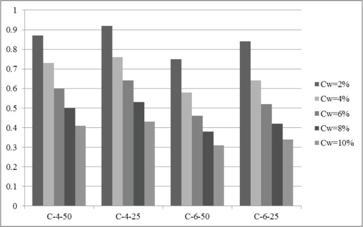
The results of the strength of the columns in the corroded and non-corroded conditions are listed in Table 2. On the other hand, the formulations proposed by Richart et al. [17] and Palter and Legeron [2] are applied to compute the increase in the strength obtained from the confinement of the circular sections with spirals and the rectangular sections, respectively. The main reason for utilizing their formulations originates from their approval by the ACI code. Accordingly, Figures 8 and 9 illustrate the changes in the compressive strength caused by the corrosion of the transverse reinforcements regarding the circular and rectangular columns, respectively.
Axial member
Name
fcc/fc
fcc(Cw)/fc
Cw = 2%
Cw = 4%
Cw = 6%
Cw = 8%
Cw = 10%
Circular column
C-4-50
1.06
0.87
0.73
0.60
0.50
0.41
C-4-25
1.11
0.92
0.76
0.64
0.53
0.43
C-6-50
1.13
0.75
0.58
0.46
0.38
0.31
C-6-25
1.26
0.84
0.64
0.52
0.42
0.34
Rectangular column
S-4-50
1.2
1.14
1.12
1.11
1.09
1.08
S-4-25
1.47
1.39
1.38
1.36
1.34
1.32
S-6-50
1.47
1.35
1.2
1.06
0.92
0.77
S-6-25
1.92
1.76
1.57
1.39
1.2
1.01
Table 2.
Strength of the columns in the corroded and conditions.
Figure 8.
Reduction in the compressive strength of the circular columns caused by the corrosion of the transverse reinforcements.
Figure 9.
Reduction in the compressive strength of the rectangular columns caused by the corrosion of the transverse reinforcements.
Based on the results obtained from the circular columns with spirals, the reduction of the compressive strength attributable by corrosion is initially large but it then decreases. In general, it can be concluded that the strength of spirals decreases because of corrosion, but this reduction is less at higher corrosion degrees. The results of the rectangular columns constructed by the stirrups demonstrated that the compressive strength initially decreases in the stirrups with a smaller diameter. However, the specimen with larger diameter becomes more sensitive to corrosion when the degree of corrosion increases. Therefore, it is recommended to use stirrups with small diameters in environments exposed to severe weather conditions. This is because such stirrups are less sensitive to high degrees of corrosion.
Generally, the corrosion of the transverse reinforcements in the circular columns reinforced by the spirals leads to a greater effect on the reduction of the strength. Furthermore, one can conclude that the reduction in the strength of the circular columns reinforced by the spirals is larger than the corresponding rate in the rectangular columns confined by the stirrups. These cases indicate that the spirals are more sensitive to corrosion than the stirrups. Thus, it is recommended that the regulations assign more requirements and restrictions to consider the effect of the corrosion on the spirals.
2.Paultre P, Légeron F. Confinement reinforcement design for reinforced concrete columns. Journal of Structural Engineering, ASCE. 2008;134(5):738-749
3.Yoshimura K, Croston T, Kagami H, Ishiyama Y. Damage to building structures caused by the 1999 Quindío Earthquake in Colombia. 1999
4.ACI 318 Committee. Building Code Requirements for Structural Concrete (ACI 318–14) and Commentary. American Concrete Institute. 2014
5.Castel A, François R, Arliguie G. Mechanical behaviour of corroded reinforced concrete beams—Part 1: Experimental study of corroded beams. Materials and Structures. 2000;33(9):539-544
6.Zhang X, Li B. Seismic performance of exterior reinforced concrete beam-column joint with corroded reinforcement. Engineering Structures. 2021;228:111556
7.Ou Y-C, Chen H-H. Cyclic behavior of reinforced concrete beams with corroded transverse steel reinforcement. Journal of Structural Engineering. 2014;140:04014050
8.Wang XH, Liang FY. Performance of RC columns with partial length corrosion. Nuclear Engineering and Design. 2008;238(12):3194-3202
9.Xia J, Jin Wl, Li Ly. Shear performance of reinforced concrete beams with corroded stirrups in chloride environment. Corrosion Science. 2011;53(5):1794-1805
10.Shayanfar MA, Barkhordari MA, Ghanooni-Bagha M. Effect of longitudinal rebar corrosion on the compressive strength reduction of concrete in reinforced concrete structure. Advances in Structural Engineering. 2016
11.Ghanooni-Bagha M, Shayanfar MA, Shirzadi-Javid AA, Ziaadiny H. Corrosion-induced reduction in compressive strength of self-compacting concretes containing mineral admixtures. Construction and Building Materials. 2016;113(15):221-228
12.Ahmadi J, Shayanfar MA, Ghanooni-Bagha M, et al. An experimental investigation into the effect of transverse reinforcement corrosion on compressive strength reduction in spirally confined concrete. Iranian Journal of Science and Technology - Transactions of Civil Engineering. 2020;44:265-275
13.Goharrokhi A, Ahmadi J, Shayanfar MA, et al. Effect of transverse reinforcement corrosion on compressive strength reduction of stirrup-confined concrete: An experimental study. Sādhanā. 2020;45:49
14.Afifi MZ, Mohamed HM, Benmokrane B. Strength and axial behavior of circular concrete columns reinforced with CFRP bars and spirals. Journal of Composites for Construction. 2014;18(2):04013035
15.Afifi MZ, Mohamed HM, Chaallal O, Benmokrane B. Confinement model for concrete columns internally confined with carbon FRP spirals and hoops. Journal of Structural Engineering. 2015;141(9):04014219
16.Regine O, Sebastian O. Textile reinforced concrete for strengthening of RC columns: A contribution to resource conservation through the preservation of structures. Construction and Building Materials. 2017;132:150-160
17.Richart FE, Brandtzaeg A, Brown RL. The Failure of Plain and Spirally Reinforced Concrete in Compression. Urbana: Engineering Experiment Station, University of Illinois; 1929 (190)
Written By
Ali Goharrokhi
Submitted: 03 October 2022Reviewed: 08 October 2022Published: 26 July 2023
 Open access peer-reviewed chapter