Open Access is an initiative that aims to make scientific research freely available to all. To date our community has made over 100 million downloads. It’s based on principles of collaboration, unobstructed discovery, and, most importantly, scientific progression. As PhD students, we found it difficult to access the research we needed, so we decided to create a new Open Access publisher that levels the playing field for scientists across the world. How? By making research easy to access, and puts the academic needs of the researchers before the business interests of publishers.
We are a community of more than 103,000 authors and editors from 3,291 institutions spanning 160 countries, including Nobel Prize winners and some of the world’s most-cited researchers. Publishing on IntechOpen allows authors to earn citations and find new collaborators, meaning more people see your work not only from your own field of study, but from other related fields too.
To purchase hard copies of this book, please contact the representative in India:
CBS Publishers & Distributors Pvt. Ltd.
www.cbspd.com
|
customercare@cbspd.com
The chapter focuses on the use of steam as the gasification agent in the thermochemical conversion of biomass to produce hydrogen-rich syngas and eventually 99.999% hydrogen after gas separations. Clean Energy Enterprises (CEE) is developing the Ways2H technology, to convert organic wastes into a syngas, from which hydrogen fuel and end-of-process solid co-products such as carbonates can be extracted while capturing carbon dioxide (CO2) emissions. Waste-to-hydrogen technologies do not generate a usable energy product directly, but indirectly, by generating a hydrogen product that can be used as clean, renewable fuel in traditional power generating plants, in hydrogen-fueled transportation equipment, and for other non-fuel purposes. The Ways2H plant design generates hydrogen in a completely closed-loop thermal gasification and separation process, with minimal air emissions as compared with waste incineration technologies as well as other known gasification processes.
*Address all correspondence to: jlkindler@gmail.com and hardikydesai@gmail.com
1. Introduction
1.1 Historical background
The earliest known investigation into gasification was carried out by Thomas Shirley, who in 1659 experimented with the “carbureted hydrogen” (now called methane).
The pyrolysis of biomass to produce charcoal was perhaps the first large-scale application of the gasification-related process. When wood, owing to its overuse, became scares toward the beginning of the eighteenth century, coke was produced from coal through pyrolysis, but the use of by-product gas from pyrolysis received little attention. Early developments were inspired primarily by the need of town gas for street lighting. The silent features of town gas from coal were demonstrated to British Royal Society in 1773, but the scientists of the time saw no use for it. In 1798, William Murdoch used coal-gas to light the main building of the Soho Foundry, and in 1802, he presented a public display of gas lighting, astonishing the local population. Friedrich Winzer of Germany patented coal-gas lighting in 1804 [1].
1.2 Biomass and its products
Biomass is formed from living species such as plants and animals—that is, anything that is now alive or was a short time ago. It is formed as soon as a seed sprouts or an organism is born. Unlike fossil fuel, biomass does not take millions of years to develop. Plants use sunlight through photosynthesis to metabolize atmospheric carbon dioxide and grow. Animals grow by taking in food from biomass. Fossil fuels do not reproduce, whereas biomass does, and, for that reason, is considered renewable. This is one of its major attractions as a source of energy or chemicals.
Every year, a vast amount of biomass grows through photosynthesis by absorbing CO2 from the atmosphere. When it burns, it releases carbon dioxide that the plants had absorbed from the atmosphere only recently (a few years to a few hours). Thus, any burning of biomass does not add to the Earth’s carbon dioxide inventory. For this reason, biomass is considered a “carbonneutral” fuel.
Of the vast amount of biomass, only 5% (13.5 billion metric tons) can be potentially mobilized to produce energy. This quantity is still large enough to provide about 26% of the world’s energy consumption, which is equivalent to 6 billion tons of oil.
Biomass covers a wide spectrum—from tiny grass to massive trees, from small insects to large animal wastes, and the products derived from these. The principal types of harvested biomass are cellulosic (noncereal) and starch and sugar (cereal).
All parts of a harvested crop like corn plant are biomass, but its fruit (corn) is a starch, while the rest of it is ligno-cellulose. The crop (corn) can produce ethanol through fermentation, but the ligno-cellulosic part of the corn plant requires a more involved process through gasification or hydrolysis [1].
1.3 Biomass gasification
Biomass gasification involves pyrolysis and partial oxidation in a well-controlled oxidizing environment. It leads to products, such as H2, CO, CO2, H2O, and hydrocarbon species. The heat required for biomass drying, heating, and pyrolysis is provided by the partial oxidation of biomass. Gasification is deemed as the most promising technology for producing renewable and carbonfree energy, as it provides tremendous flexibility with regard to feedstock and the fuels produced. In general, the gasification process converts low-value biomass to a gaseous mixture containing syngas (mixture of H2 and CO) and varying amounts of CH4, and CO2. It can also produce hydrocarbons, particularly in the lower temperature range. The oxidizing agents can be pure O2, air, steam, CO2, or their mixtures. The syngas composition can be varied by using air and steam as the gasification agent. Moreover, the presence of CO2 can be used to increase H2 and CO contents, as it transforms char, tar, and CH4 into H2 and/or CO in the presence of a catalyst such as Ni/Al. Numerous studies have been reported in the recent years, dealing with the type of reactors used for gasification, thermo-chemical processes involved, and various gaseous and liquid fuels produced during gasification. The syngas can be used to generate heat and power, for example, in an IGCC facility, produce H2, and synthesize other chemicals and liquid fuels such as F-T fuels. There are various routes for the utilization of syngas, including the production of F-T and other transportation fuels. The global reactions associated with syngas formation from biomass (CHn) include the following:
2CHn+O2⇒nH2+2COE1
CO+H2O⇒H2+CO2E2
CH4+H2O⇒3H2+COE3
Reaction (1) corresponds to syngas formation in the presence of O2, while reaction (2) is the well-known water-gas-shift-reaction and reaction (3) is associated with the steam reforming of methane. Reactions (2) and (3) are used to control the H2/CO ratio. The production of F-T fuels from syngas involves a series of reactions in the presence of a catalyst. The global reactions for this process can be written as follows:
nCO+2n+1H2⇒CnH2n+2+nH2OParaffinsE4
nCO+2nH2⇒CnH2n+nH2OOlefinsE5
The first step during F-T formation is the conversion of syngas into –CH2– alkyl radicals and H2O. The –CH2– alkyl radicals then combine in a catalyst reaction to produce synthetic paraffin and olefin hydrocarbon (HC) fuels of various chain lengths. The amount and type of fuels formed are determined by parameters such as temperature, pressure, H2/CO ratio, and the type of catalyst. In general, F-T fuels can be produced from a variety of solid, liquid, and gaseous sources, and further processed to yield clean transportation fuels with desired specifications.
Regardless of feedstock or process, F-T fuels have a number of desirable properties. For example, F-T diesel fuels can be produced with a high cetane number, with ultra-low sulfur and aromatic content, with the consequence of improved engine performance, significantly lower particulate mass (PM) emissions and favorable NOx/PM trade-off. However, these fuels generally have poor lubricity and lower volumetric energy density. These shortcomings can be alleviated by blending these fuels with petro-fuels. Thus, the biomass gasification can be used to produce syngas and subsequently clean drop-in transportation fuels. The effects of F-T fuel properties on engine performance and emissions have been reported by a number of investigations [2].
1.4 Gasification medium and types of gasification agents
A gasifying medium assists to break down the heavier solid hydrocarbons in order to convert them into low-molecular-weight gases such as CO and H2. There are a few well-known gasifying agents used in the process of biomass gasification, namely air, steam, oxygen, and carbon dioxide.
The influence of using different agents on energy efficiency has been studied extensively in the literature [3, 4]. For instance, Sharma et al. [3] conducted an experimental study on biomass gasification process in a downdraft reactor followed by saturated steam when the steady-state conditions achieved. They indicated that adding steam to air in the reduction zone increased the hydrogen flow rate. Ismail and El-Salam [4] studied air gasification of biomass in an updraft reactor and indicated that equivalence ratio, which is a function of both air and biomass, influenced the composition of synthesis gas. They concluded that the equivalence ratio has an indirect relation with the concentration of CO and H2 while interacting directly with the CO2 content of the gas [3, 4].
1.5 Types of gasifiers
There are several types of biorefinery reactors that impact the thermochemical conversion, for example, updraft, downdraft, cross-draft, fluidized bed, and entrained flow gasifier which fall into the three main categories: (1) moving (fixed) bed, and (2) fluidized bed and (3) entrained flow gasifier. Moving bed and fluidized bed gasifiers are discussed here.
1.6 Moving bed gasifiers
Updraft gasifiers are the most straightforward configuration in moving bed reactors. In a conventional updraft gasifier, fuel is fed from the top, while the syngas leaves from the top. The gasifying agent (air, oxygen, steam, or their mixture) is pre-heated and fed into the gasifier through a grid at its bottom.
In a downdraft gasifier, biomass is fed from the top, while the entered gasification agent meets with the pyrolysis product, releasing heat. After that, both gas and solid (char and ash) products move down in the downdraft gasifier. Here, a part of the pyrolysis gas may burn above the gasification zone; this phenomenon, called as flaming pyrolysis, supplies the thermal energy required for the endothermic reactions through the combustion of pyrolysis gas. Drawbacks of a downdraft gasifier are namely grate blocking, channeling, and bridging which hinder scaling-up the gasification process. The moisture content of feedstock in a downdraft gasifier should not exceed 30% to avoid inferior products and low efficiency. A downdraft gasifier is beneficial for producing low-tar syngas and has a simple operation configuration. The syngas of a downdraft gasifier has less tar as well as lower LHV compared to an updraft [5].
1.6.1 Fluidized bed gasifier
Unlike other types of biorefinery reactors mentioned earlier, fluidized-bed gasifier contains non-fuel granular solids (bed solids) that act as a heat carrier and a mixer. The two types of fluidized bed are circulating fluidized bed and bubbling fluidized bed, differing in fluidization techniques. In a bubbling fluidized bed, the fuel fed from either the top or the side is mixed quickly throughout the fluidized bed. The gasifying medium serves as the fluidizing gas and is sent through the bottom of the reactor, leading to a quicker mixture of fuel particles with the bed materials and thus much faster heating of the fuel. More rapid drying and pyrolysis processes occur in the bubbling fluidized bed gasifiers compared to the circulating type. A deficiency of this system is that partially gasified particles can exit the process as a result of mixing with gasified solids. The combustion reaction occurs in the fluidized phase resulting in a lower efficiency [5].
1.7 Typical gasifier design
Gasification is a relatively old technology that has been in use throughout the industrialized world for approximately 200 years. During the nineteenth century, “town gas” was produced from coal and peat and used as an industrial fuel and municipal gas supply for street and home lighting. The first manufactured gas plant in North America was opened in Baltimore, Maryland, in 1816. Since the 1920s, gasification has been used for the synthetic production of chemicals (methanol, ammonia, etc.). Being petroleum-poor but coal-rich, Germany used gasification coupled with the Fischer-Tropsch process during World War II to produce liquid fuels. Fischer-Tropsch production accounted for an estimated 9% of German war production of fuels and 25% of the automobile fuel supply. Similarly, in South Africa, another country with large coal reserves but little oil, SASOL started commercial production of diesel and gasoline in 1952 using coal gasification and the Fischer-Tropsch process.
Gasification can be thought of as a partial combustion process where steam reacts with the carbon in a solid carbonaceous fuel or feedstock via the general reaction:
C+H2O−>CO+H2E6
This reaction occurs at high temperatures (800–1000°C, 1472–1832°F). It is an endothermic process, meaning that heat is consumed by the reaction and a source of heat is required to support it. In a traditional gasifier, this heat is generated by providing just enough air or pure oxygen to achieve the desired gasification temperature in order to sustain the gasification reactions. That is the partial oxidation process. This combustion burns fuel/feedstock via the following general combustion reactions:
C+1/2O2−>COE7
CO+1/2O2−>CO2E8
H2+1/2O2−>H2OE9
There is an inherent trade-off between the desired gasification temperature and the amount of feedstock that is consumed to generate the heat required. Partial oxidation “consumes” feedstock and as such reduces the potential for free hydrogen production [5].
Interestingly, at high temperatures another well-known chemical reaction, named the water-gas shift (WGS) reaction, occurs:
CO+H2O<−>CO2+H2E10
This is a reversible reaction that will eventually reach an equilibrium condition where the rate of reaction to the right equals the rate of reaction to the left. The equilibrium composition of CO, H2O, CO2, and H2 is a function of the amount of carbon, oxygen, and hydrogen available and system temperature. According to the reaction stoichiometry shown in Eq. (5), if CO2 could be selectively removed, then the reaction would shift to the right, producing more H2. Minimizing the production of CO2 via combustion helps to maximize the production of hydrogen, which leads back to the inherent trade-off between a desirable gasification temperature and the amount of feedstock that is “sacrificed” to maintain this temperature.
A gaseous mixture of CO, H2O, CO2, and H2 is commonly referred to as synthesis gas (syngas). A variety of follow-on technologies are used to convert syngas to methane, methanol, acetic acid, gasoline, diesel, waxes, etc. Syngas can also be burned cleanly in a burner or fuel cell and purified hydrogen can be produced using a pressure swing absorption (PSA) process to selectively remove hydrogen from the syngas.
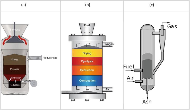
The most common gasifier types are shown in Figure 1. Note that these gasifier types involve a single reaction vessel where all reaction zones occur in the single vessel.
A typical downdraft gasifier is presented in Figure 1(a). The reactor volume consists of a bed of solids starting with fresh feedstock fed at the top converted to residual char at the bottom. The feedstock moves down the reactor under the influence of gravity. Table 1 lists the reaction zones that occur in a downdraft gasifier and the range of temperatures for each zone.
Reactor Zone
Temp. Range
Heat of Reaction
Drying
> 150 °C
Endothermic
Pyrolysis
150–700°C
Endothermic
Combustion
700–1500°C
Exothermic
Reduction
800–1000°C
Endothermic
Table 1.
Reaction zones in a downdraft gasifier.
As feedstock particles are dried, pyrolyzed, partially combusted, and gasified (reduced), the particles decrease in size and the bed density increases. A small amount of air is introduced with the feedstock at the top of the gasifier, but the majority of air is introduced in the combustion zone. Heat released by combustion facilitates pyrolysis and drying by radiant heat transfer. The char leaving the combustion zone is heated to gasification temperatures. The syngas moves concurrently with the solid bed and is drawn off after the reduction zone.
Ash and char fall through the bed grate and are collected from the vessel bottom.
In Table 1, the heat of reaction is listed for each zone. Drying, pyrolysis, and reduction reactions are mostly endothermic (heat is absorbed), while the combustion zone is exothermic (heat is released). It is interesting to note that drying temperatures exceed the normal boiling point of water (100°C @ atmospheric pressure).
Forcing water out of the feedstock fibers is a diffusion process that requires more energy than simply the heat of vaporization of water.
An updraft gasifier, Figure 1(b), is similar to a downdraft gasifier except that all air is introduced at the bottom of the gasifier and the produced syngas leaves at the top of the reactor. Notice, due to where the air is introduced, the relative locations of the combustion and reduction zones flip. At the bottom of the gasifier, the residual gasification char is burning to heat up the rising gas as well as provide radiant heat for the higher reaction zones.
A fluidized bed gasifier, Figure 1(c), uses a non-combustible bed material such as sand to transfer heat and facilitate mixing in a bubbling or fully fluidized regime. Feedstock enters the reactor, coming in contact with hot sand. The air and evolving syngas are at a high enough velocity to cause the sand and feedstock to rise. As the feedstock rises up the reactor, it undergoes the various stages of gasification. A gas-solid cyclone is used to separate the produced syngas from the fluidizing medium. In a bubbling bed, velocities are maintained so that the majority of the sand will stay in the bottom half of the reactor. In a fully fluidized bed, the gas velocity is high enough to carry almost all of the sand overhead where it is recovered by the cyclone and returned to the bottom of the reactor.
Indirect heating presents the advantages of causing little or no consumption of feedstock, making most of the fuel (feedstock) available for the gasification reactions. However, the management of the sand in the reactors can become problematic as it raises issues with energy consumption to maintain the flow, as well as maintenance concerns resulting from abrasion due to contact between sand and the reactor wall.
1.8 Gasifier reaction chemistry
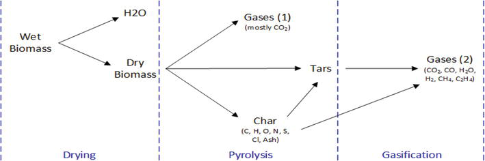
A general reaction network for feedstock gasification is presented in Figure 2.
Figure 2.
Generalized reaction network for feedstock gasification.
Wet feedstock is dried by hot rising gases and/or radiant heat from the combustion zone. Usually, feedstock is dried externally to 10–20 wt% moisture before being used as a feed to a gasifier. At this level of dryness, the water that remains is bound in the fibers and interstitial spaces of the feedstock. Energy is required to increase the diffusion rate of water from the tightly wrapped fibers. This explains why drying occurs at temperatures above the normal boiling point for water.
As the temperature of the feedstock approaches 150 to 180°C, the feedstock begins to breakdown into smaller molecular compounds, including gases, tars, and char. The tars are aromatic and phenolic compounds in their vapor form. For wood and agricultural residues, the glucose and pentose rings in cellulose and hemicellulose, and the phenol groups in lignin yield these tars. The final char mostly consists of carbon and represents the fixed carbon that is analyzed to characterize it as a solid fuel (proximate analysis).
Pyrolysis involves a complicated set of thermal cracking reactions that are difficult to characterize beyond the empirical treatment of the reaction network shown in Figure 2. The overall gasification (reduction) reactions, presented in Table 2, are more easily characterized. These reactions consist of three groups: (1) reactions involving steam, (2) reactions involving hydrogen, and (3) reactions involving carbon dioxide.
Reactions
Reaction Stoichiometry
∆Hreaction (MJ/kmol)
Reaction Name
R-1
C(s) + H2O(g) → CO(g) + H2(g)
+131
Steam Gasification
R-2
CO(g) + H2O(g) ↔ CO2(g) + H2(g)
−41
Water-Gas Shift
R-3
CH4(g) + H2O(g) → CO(g) + 3H2(g)
+206
Steam Methane Reforming
R-4
CnHm(g) + H2O(g) → nCO(g) + (n + m/2) H2(g)
< 0
Steam Tar Reforming
R-5
C(s) + 2H2(g) → CH4(g)
−75
Hydrogasification
R-6
CO(g) + 3H2(g) → CH4(g) + H2O(g)
−227
Methanation
R-7
C(s) + CO2(g) → 2CO(g)
+172
Boudouard
R-8
CnHm(g) + nCO2(g) → 2nCO(g) + (m/2) H2(g)
> 0
Dry Tar Reforming
Table 2.
Gasification reactions.
Notice, that the gasification reactions are actually a mix of endothermic (∆Hrxn > 0) and exothermic (∆Hrxn < 0) reactions. However, on balance, the reduction zone is net endothermic.
Table 3 lists the overall combustion (oxidation) reactions where CnHm(g) represents tar species. All oxidation reactions occurring in the combustion zone are exothermic. The combustion heat is transferred by heating up the local gas and solids as well as by radiant heat transfer to the other sections of the gasifier.
Reactions
Reaction Stoichiometry
∆Hreaction (MJ/kmol)
Reaction Name
C-1
C(s) + 1/2O2(g) → CO(g)
−111
Carbon Partial Oxidation
C-2
CO(g) + 1/2O2(g) ↔ CO2(g)
−283
CO Oxidation
C-3
H2(g) + 1/2O2(g) → H2O(g)
−242
H2 Oxidation
C-4
CnHm(g) + n/2O2(g) → nCO(g) + m/2H2(g)
< 0
Tar Oxidation
Table 3.
Combustion reactions.
1.9 Waste to hydrogen: general process
A process targeting carbonaceous matter conversion into hydrogen will require a combination of specific features that include (but not limited to):
Little or no partial oxidation of the feedstock
Constant, high reaction temperatures to maximize hydrogen production and avoid tar persistence.
Controlled presence of water vapor
All waste to hydrogen projects must begin with feedstock preparation, which includes sorting, sizing, storage, and feeding. Feeding can be the most difficult as the feedstock must be isolated from the hot process and fed to the process in a controlled flow, particularly when it contains a substantial number of plastics, which can melt and cause mechanical issues in the feeding system.
The feedstock is fed into one of several types of pyrolyzers or gasifiers: fluidized bed or fixed bed type. These are typically heated to 600–650°C either directly through combustion or indirectly via intermediate thermal media, such as sand or ceramic balls. Combustion obviously burns part of the feedstock, which includes the product. Indirect heating has the partial heat losses associated with heating an intermediate media, which then heats the feedstock and the heat losses, as well as that increases CAPEX, of significant additional equipment. The syngas exits from the pyrolyzer and the thermal media and char exit the bottom and are separated. The thermal media is then conveyed up to the preheater where is it cross exchanged with the flue gas from the process heater, which burns the char and the off-gas from the hydrogen separator. With partial oxidation solutions, the challenge lies in producing as little combustion byproducts as possible, particularly when processing complex waste mixes such as municipal solid waste.
The syngas from the pyrolyzer is then typically reformed to 1000–1100°C by the combustion of part of the syngas with the addition of oxygen. Reforming to 1100°C does crack some of the light hydrocarbons, tars, and fine char while reforming reactions occur.
The reformed gas is then treated to cool the gas via a quench tank, waste heat boiler, and scrubber. The reformed gas is then treated by an amine system or specialty scrubbers to remove the gases such as: ammonia, hydrogen cyanide, hydrogen sulfide, hydrochloric acid, carbonyl sulfide. Once those contaminants are removed, the reformed gas is processed through a Pressure Swing Absorber (PSA) to separate the carbon monoxide and carbon dioxide from the hydrogen, the final product. The hydrogen recovery from the PSA is about 72%. The remaining 28% of the hydrogen and the reject or off-gas from the PSA can then be reused either internally in the system, or for additional third-party processing, such as a gas engine.
As discussed above, Ways2H recognized the disadvantages of the past processes and competitive technologies in detail, as well as some innovative commercial technologies that could be applied to waste to hydrogen conversion. In applying these technologies to the design of the Ways2H process, the object was to simplify the process, eliminate certain equipment, decrease operating expense, and increase hydrogen yield.
Some solutions use heat carriers as the pathway for feedstock indirect heating. While this solution seems to bear several advantages, implementing a heat carriers circuit within the process is also source of complexity; therefore, cost increases. Eliminating the use of thermal media, such as the heat carriers above as well as fluidized bed removes the need for the following:
A thermal media preheater that cross-exchanges the media with flue gas from the process heater,
A process heater or combustor itself which is a source of emission of NOx and wasted energy,
A mechanical conveyor which transports the media,
A char separator and conveyor necessary to separate the char from the media after pyrolysis,
Expensive and complex valves systems,
In summary, a great deal of capital and operating cost.
Another process type recently evaluated was plasma gasification. In this process, the heat required for feedstock gasification is provided via generation of a plasma, typically reaching temperatures in the range of 4000°C. In addition to significantly high CapEx, these solutions require a high maintenance, particularly with the reactors’ internal walls, subject to relatively high temperatures compared with conventional Vapolysis or pyrolysis, as well as the electrodes that generate the arc for plasma generation. Made of graphite, these electrodes are essentially expensive consumables.
Then of course, there are several processes on the market using more conventional solutions like partial oxidation of raw feedstock as the heat source. There are well-known cases where these processes, which are very effective for predictable, stable feedstock streams such as wood or coal, have been plagued by mechanical incidents, mostly caused by tar occurrence, due to too low temperatures in the gasification/pyrolysis reactors.
The challenge then is to provide enough heat to ensure full gasification without combusting the hydrogen-generating components of the feedstock with a mechanically simple configuration. In order to accomplish full gasification without the complexity and cost of an intermediate media, an alternate source of energy is required for the thermal cracking reactions—vapolysis—to occur. The solution is based on the choice of a high-temperature heat source for the reformer, and then to utilize the hot syngas from that reformer as the heat source for vapolysis. A device producing a reforming temperature approximately at 1400°C was identified.
However, the challenge was to utilize the heat from the reformed gas, avoid the use of solid thermal media, and yet to keep the reformed gas separate from the gas in the vapolysis process. Two technologies were evaluated: an indirectly heated rotary kiln or an indirectly heated screw conveyor. Rotary kilns are typically used to heat solids to the point where a chemical reaction or physical change takes place, in this case: drying, devolatilization, and vapolysis, which makes the kiln’s temperature control critical. A rotary kiln is comprised of a rotating cylinder (called the drum) and jacket, which surrounds the drum (sometimes called the furnace), sized specifically to meet the temperature and retention time requirements of the material to be processed. The kiln is set at a slight angle, in order to allow gravity to assist in moving the feedstock through the rotating cylinder. Mechanical rotation movement also assists in breaking the eventual feedstock clusters that may arise. The problem arises in the mechanical lip seals and bridging between the furnace and rotating drum. These seals are mechanically difficult to build and maintain. In addition, the leakage of these seals or their failure led to highly flammable gases leaking to the atmosphere [6].
2.2 Main features of the process
Screw Vapolyser is a modified version of an indirect heated screw conveyor. It has several advantages:
Initially, feedstock is shredded and pre-processes by several mechanical operations to suit the quality of feedstock with Screw Vapolyser processing. The feedstock is shredded up to inches of size to have smooth gasification by increasing the reaction rate.
The feedstock is thoroughly mixed by the mechanical action of the screw itself, promoting the vapolysis process.
Steam is added in Screw Vapolyser as gasification agent.
The rotating screw also increases the heat transfer to the feedstock as well increases the reaction efficiencies between steam and feedstock, which helps to have efficient gasification.
The feedstock is gasified in the lower portion of the screw and the syngas is separated from the solids in an upper zone.
A suction blower pulls the syngas from the Vapolyser into gas mixer and reformer for those gaseous reactions that generate more hydrogen. The unconverted portion of feedstock, which is mainly inorganic in nature, comes out as bottom ash at the end of the screw.
Reformer is refractory lined reactor with 1400°C operating temperature. Such a high temperature is achieved using part of the hydrogen produced as fuel through oxy-fuel burner (OFB).
The 1400°C reformed gas from the reformer provides the gasification energy for Vapolysis at very little CapEx or OpEx.
The 1400°C reformed syngas flows through an enclosure, which surrounds the screw conveyors tube. There are no seals except on screw shaft, which uses a conventional rotary seal.
The temperature differential between the reformed gas and the feedstock/Vapogas is much greater than any intermediate media solution.
The reformed gas, after having released its certain portion of heat to the Screw Vapolyser, is cooled down, cleaned, dried and undergoes a final conversion phase, Water Gas Shift Reaction, where carbon monoxide is removed to produce more hydrogen. Prior to entering the Water Gas Shift Reactor (WGSR), gas must be heated up to 250 to 300°C, as per particular operating temperature requirement, for better conversion and reaction rates in WGSR.
Separation phases yield:-
Hydrogen product, of which a fraction is diverted to feed the burner in the HT reformer
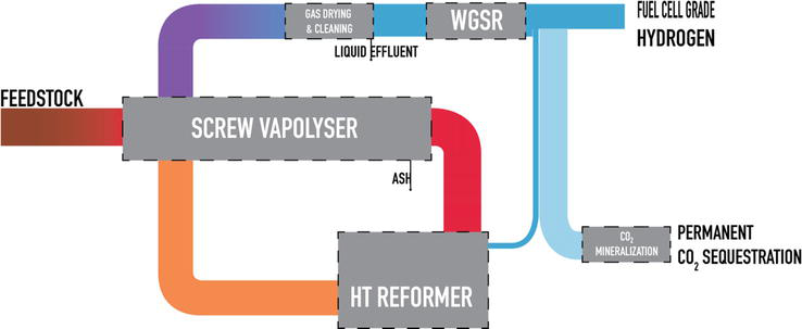
Carbon dioxide, which is sent to an integrated mineralization component. The output from this component is mineralized carbon, permanently sequestered and available for example as a construction material or for concrete/cement manufacturing processes (Figure 3) [6].
Figure 3.
Overall Ways2H process schematic.
Feeding the Vapolyser, the organic feedstock is first preheated with excess process steam to remove excess moisture in the feedstock if any. The feedstock then enters the Vapolyser through a rotary gas lock, which not only meters the feedstock into Vapolyser but seals the gases being generated in the Vapolyser, preventing them from flowing back into the feedstock line. As the feedstock passes through the Vapolyser, it is exposed to a controlled temperature, which gradually increases the feedstock from its initial—ambient—temperature to final temperature of 850°C, which is much higher than gasifiers using intermediate media.
The vapolysis temperature of 850°C is achieved by transferring the reformed gas heat at 1400°C, directly, through the jacket enclosure of the Vapolyser. This would cause the vapolysis process to occur while raising the feedstock temperature to 850°C. At this point, with exception of a minimal remaining solid carbon fraction (char) and mineral fraction (ash), the feedstock is totally converted to syngas, essentially its elemental gases, such as hydrogen, carbon monoxide, carbon dioxide, methane, and small amounts of contaminants such as hydrochloric acid, hydrogen cyanide, ammonia, COS, and hydrogen sulfide. The syngas then flows to the reformer with any remaining entrained tars after passing through the “Gas mixer/Static Mixer” where more steam is added stoichiometrically required by the reforming process. The only waste product is a minimal amount of ash that may result from solid char decomposition. This ash will be removed from the bottom of the Screw Vapolyser.
The syngas and char enter the reformer where they are exposed to an Oxy-Fuel Burner (OFB), which exposes the Vapogas and any leftover tar from the Vapolyser to temperatures of 1400°C. Additional steam provision is there in the reformer if required. In the OFB, oxygen, in stoichiometric proportion, is mixed with fuel, which is 99.999% pure hydrogen from the Hydrogen Storage/Hydrogen Separator product stream.
Combustion of this fuel yields a flame of over 2000°C and temperatures in excess of 1400°C in the reformer. At this temperature, essentially all of the methane and tars are cracked to hydrogen and carbon monoxide, increasing the hydrogen content over a conventional reformer by about 10 to 15%. In addition, contaminant gases such as ammonia and hydrogen cyanide are converted to nitrogen and water, eliminating NOx emissions.
The OFB hot gas (combustion products) accelerates to sonic velocity through a specifically designed nozzle, forming a turbulent jet. This turbulent jet has an enormous entrainment appetite that enhances mixing between the Vapogas containing tar/methane and the reactive hot steam. The combination of high temperature and rapid mixing makes the jet extremely reactive. Therefore, the OFB process can provide better syngas (defined as CO and H2) yields than if conventional oxygen injection solutions were used in a typical reformer.
In addition to the existing mixing effect directly caused by the OFB nozzle, Ways2H has developed and integrated a proprietary static mixing component, which through an innovative use of aerodynamics principles further increases the gas flow reactivity and provides an improved mixing of the injected steam with the Vapogas flow before entering the reformer.
The combined reformed gas and OFB combustion gases exit the reformer and enter the various sections of the vapolysis jackets through temperature control valves. Each valve controls the flow of 1400°C reformed gas to each jacket section according to the desired temperature for each stage of the vapolysis. There is a control on the flow entering the vapolysis heating jackets, which allows extra hot reformed gas to bypass the heating jacket and is directed to the Waste Heat Recovery Boiler (WHRB).
After exiting the vapolysis jackets, the reformed gas then enters heat recovery, cleaning, and separation phase. The reformed gas from the jacket of the Vapolyser is at approximately 1000°C and enters waste heat recovery boiler, which generates process steam for preheating the feed and injection into the Vapolyser, Gas Mixer/Static Mixer, and reformer. The reformed gas then enters a quench tank, which cools the reformed gas. The reformed gas then enters a dual scrubber further cools the gas and completes the removal of contaminants. After scrubbing down acidic gases, a fine particulate filter (<0.5 micron) helps removing all particles still present and gases will be free of acids and particles at this stage. A compressor increases the reformed gas pressure and electric heater increases the temperature required to feed the Water-Gas Shift Reactor (WGSR).
Water-Gas Shift Reactor (WGSR) is used to convert carbon monoxide (CO) into carbon dioxide (CO2) and hydrogen (H2) with the help of added steam. This step is very useful to enhance the hydrogen production.
The gas then enters a carbon dioxide separator and removes almost all carbon dioxide, which is then fed to the Carbon Capture & Mineralization (CCM) system. This system mineralizes the carbon dioxide with Ca+, Mg+, CaO, Ca(OH)2, MgO, Mg(OH)2 from various natural as well as a by-product sources from other industrial processes to form calcium, sodium, or magnesium carbonate. The advantages of the CCM technology over traditional Carbon Capture Storage (CCS) technology are the conversion of CO2 to a stable, storable, and usable carbonate compound. Eventually, all the carbon entering the process in the feedstock as well from the burners/gas engine will find its way to CO2 and ultimately mineralize as carbonate, making the whole process a full carbon sink.
At this stage, the gas is free of carbon dioxide (CO2) and has majorly hydrogen (H2), carbon monoxide (CO), nitrogen (N2), and traces of Hydrogen Sulfides (H2S)/other sulfur compounds. This gas mixture is all set to be processed through Hydrogen Separator, which requires further sulfur removal and concentration below 50 PPB. To achieve the limit on sulfur presence, sulfur removal system is used to remove sulfurs prior to be treated by Hydrogen Separator.
The OFB nozzle uses 99.99% Hydrogen (H2) to generate 1400°C reformed gas, which in turn provides the energy for feedstock gasification in the Screw Vapolyser and the auxiliary burner (if required) use the off-gases or waste gases from the process to provide heat to Screw Vapolyser if hot-reformed gas heat supply is not sufficient to bring up and maintain the temperature of Screw Vapolyser up to 850°C.
There is an exhaust from the Hydrogen separator system, which is still having mainly carbon monoxide (CO), Hydrogen (H2), and Nitrogen (N2). This exhaust stream can be used either by Aux-Burner for Screw Vapolyser if required, and if not, this stream can be used by Gas Engine/SOFC to generate electricity for captive use and as discussed above, the exhaust of electricity generation system, having carbon monoxide (CO2), again diverted to CCM system for mineralization [6].
2.3 The Ways2H process equipment
In order to achieve the above process, Ways2H utilizes a series of commercially proven processes or components that are operated within their design limits.
The first stage of Vapolysis takes place in a Vapolyser, which is a heated shaftless screw conveyor.
The typical Vapolyser with a feedstock inlet, a Vapogas outlet to the Reformer, a bottom outlet for the inorganic ash fraction of the feedstock, a heating jacket surrounding the conveyor, and an external motor.
The hot gas from the Vapolyser then enters the Reformer where it is heated to 1400°C by a direct flame. The 1400°C gas from the Reformer then passes through the Vapolyser jacket, indirectly heating the feedstock to 850°C, achieving the vapolysis of the feedstock to its elemental gases of mainly hydrogen, carbon dioxide, carbon monoxide, and methane. The 850°C Vapogas temperature is controlled by the flow of gas from the reformer to the jacket. The Ways2H 850°C Vapogas is much hotter than the 600°C pyrolysis gas typical in the industry, achieving more complete gasification of tars and char industry typically calls this mixture of gases, syngas (Figure 4).
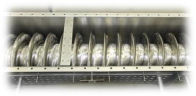
Figure 4.
Internal view of Screw Vapolyser.
The conveyor screw’s, shown here, main function is to move the organic feedstock along the conveyor tube to provide uniform mixing, cluster breaking, and better heat transfer from the conveyor tube to feedstock. In these applications, the materials of construction are designed to withstand temperatures of over 1000°C with alloys such as: Nitronic 60 or Inconel 625 type. The conveyors like this are used by many similar applications, including in the pyrolysis and calcination industries.
Before further processing, the high-temperature Vapogas is sent through a Particulate Filter in order to remove the particles above 1 micron size. The particulate filter is a metallic mesh-type filter provided by several suppliers. The second phase of Vapolysis takes place in a Gas Reactor where the Vapogas and additional steam are injected via static mixers. The Gas Reactor is sized to allow sufficient residence time for certain gas reactions to occur.
The third and final stage of Vapolysis occurs in the Reformer.
Reformer is a process used in almost all petroleum industries. Gas reformers in one or other way process the raw gas to achieve highest concentration of targeted product. Steam reformers are the current mainstream pathway for hydrogen production, with methane (natural gas) as feedstock. As such, it is also a well-known, widely used technology.
In the third and final phase in the Ways2H Vapolysis process, Vapogas from the Vapolyser passes into a High Temperature Reformer to cause certain gas reactions to occur. In order to achieve 1400°C exhaust gas that enters the Vapolyser jacket, the Ways2H Reformer uses a commercial size oxy-fuel burner, which burns a small fraction of the ultimately produced hydrogen with oxygen, achieving much higher temperatures and the breakdown of methane to hydrogen.
The high-temperature flame heats the Vapogas to over 1400°C—from that step it is called Hot Reformed Gas. The Hot Reformed Gas then passes through the jacket of the Vapolyser, achieving an optimal efficiency of thermal energy utilization.
The process has now completed the Vapolysis stages and commences the Reformed Gas treatment and separation processes. The first stage is the cooling of the gas and the generation of steam for the various gas reactions.
After Hot Reformed Gas passes through the Vapolyser jacket, its temperature is about 1000°C. It then enters a conventional waste heat recovery boiler. The boiler generates steam for injection into the Vapolyser, Reformer, and Water Gas Shift Reactor. The steam is actually a source of added hydrogen for the reactions that occur in these vessels. In addition, the gas is cooled for subsequent processes.
The waste heat recovery boiler concept is already a well-known and proven technology. There are several WHRB Designer/Manufacturers/Suppliers available globally.
The cooled gas then passes into a standard Dual Scrubber, which removes low levels of contaminants such as: HCl, NH3, HCN, and COS, which were introduced in the feedstock as trace components. Those trace elements must be removed to allow the gas to be effectively separated in downstream systems and not to contaminate or poison media or membranes in downstream systems. Gas scrubbers are commonly available systems, which will be selected based on our requirement as per the pollutants’ concentration in our process gas.
The entire system starting from Screw Vapolyser to Gas Scrubbers is operated under slight vacuum. An ID fan/Suction fan at the end of Gas scrubber is responsible for maintaining the gas flow and pressure from throughout up to ID fan/suction fan outlet.
Induced Draft Fan/Suction fans are impeller-based motor driven fans, and the speed is controlled by various differential pressure points at various processes. These type ID fans, well-designed according to the Ways2H process gas and operational requirement, are commonly available.
The treated gas is then pressurized with a typical dual acting reciprocating compressor and heated in heat exchanger prior to entering the Water Gas Shift Reaction (WGSR). The WGSR requires a certain pressure and temperature for efficient operation.
The WGSR is a widely used industrial reaction for the manufacture of ammonia, hydrocarbons, methanol, and hydrogen. In the manufacture of hydrogen, the carbon monoxide is mixed with steam in the presence of certain catalyst to convert the carbon monoxide to carbon dioxide and additional hydrogen. After removing the contaminants that could poison the catalyst, the Reformed Gas in the Ways2H process gas, which still has a significant concentration of carbon monoxide, is processed to produce significantly more hydrogen with minimal energy consumption.
After the Reformed Gas passes through the WGSR, it consists mostly of carbon dioxide, hydrogen, nitrogen from the feedstock and trace sulfur contaminants. The next step in purifying the gas to hydrogen is to separate the carbon dioxide.
Pressure Swing Adsorption (PSA) or Vacuum Pressure Swing Adsorption (VPSA) or any other commercially proven and available membrane and absorption technologies are two well-known variants of a technique used to separate some gas species from a mixture of gases under pressure/vacuum/normal pressure according to the species’ molecular characteristics and affinity for an adsorbent material. It operates at near ambient temperature and significantly differs from cryogenic distillation, another process commonly used to separate gases.
For the removal or separation of carbon dioxide, Ways2H uses proven CO2 separators technologies for the highest efficiency. The separated carbon dioxide then flows to the CCUS system, which is discussed later.
The retentive gas from the CO2 separator is primarily hydrogen with nitrogen from the feedstock and small amounts of carbon dioxide and carbon monoxide. Prior to the final separation of fuel cell grade hydrogen, sulfur compounds that were not removed in the scrubber must be removed to prevent poisoning the palladium in hydrogen separation membranes.
Before the hydrogen can be separated from the treated gas, it must be pressurized and heated, similar to the conditioning process used before the WGSR, using a second dual acting reciprocating compressor and heat exchanger.
The final step in the production of fuel cell grade hydrogen is to remove the nitrogen due to the feedstock and small amounts of carbon dioxide and carbon monoxide left from the WGSR and CO2 separators. To achieve the fuel cell grade hydrogen, the treated feed gases are passed through a commercial palladium membrane system to separate the fuel cell quality hydrogen from the waste gas. The waste gas along with the nitrogen is then burned to provide an additional thermal energy source for the Vapolyser or the WGSR heat exchanger or hydrogen separator heat exchanger. A small fraction of the hydrogen product is burned in the reformer’s oxy-fuel burner.
The final major product of the Ways2H process is the Carbon Capture Use & Storage (CCUS) of the separated carbon dioxide from the CO2 Separator. The carbon dioxide is then sent to mineralization process for carbon sequestration into carbonate/solid form.
Bottom line, Ways2H achieves the conversion one dry ton per day of organic waste to a net output of approximately 150 kg per day of fuel-cell grade hydrogen using conventional, industrially proven, and commercially available equipment operating in a unique temperature and sequential profile [6].
The technical aspects of the process have been outlined above, showing the particularly promising performances in terms of hydrogen yield, when calculated on the basis of feedstock input.
Technical performance does not provide much benefit if the solution cannot be economically deployed and operated. To estimate the economic feasibility of the solution, we chose to focus on two main indicators, one being the overall economic performance, expressed as project Internal Rate of Return (IRR). The other performance indicator is the hydrogen production cost. The following estimation is based on a system being built and operated on a generic site in the continental United States, with basic CapEx and OpEx numbers provided as follows.
3.1 Capital expenditure (CapEx)
Table 4 below outlines the main cost elements of a fully delivered, commissioned turnkey plant. The retained perimeter (battery limits) starts with processed feedstock injection, and ends with products (hydrogen and byproducts) output, conditioning thereof not included.
CapEx (Capacity in tpd)
24
Average estimated H2 production per day (kg)
3600
Equipment cost estimation
Purchased equipment
Concrete
Controls
Electrical
Fire Protection
Heat Trace & Insulation
Mechanical
Rentals
Site work
Structural - Equipment
Structural—Pipe Supports
System Install & Commissioning
Miscellaneous
Other Direct costs
Direct Costs
19,524,890
Peripheral Equipment
Preprocessing
No
—
Fuel Cell
No
—
Compressor (bar)
No
—
Other additional Equipment
No
—
Contingencies
5%
976,245
Complete system
24 tpd
20,501,135
Initial Project Assessment
90,000
Basic Engineering
424,645
Detailed Engineering
2,406,321
Project supervision & Management
2%
410,023
Insurance
2%
410,023
Indirect costs & Engineering
3,741,012
Total cost before grants
24,242,146
Table 4.
Delivered system CapEx.
3.2 Operational expenditure (OpEx)
As most industrial processes, the plant requires several utility connections to operate. Table 5 below summarizes all considered costs for system operations. It is important to note that in an alternative configuration, the plant can be equipped with an internal stationary fuel cell to produce its own electricity and as such be able to operate off-grid. It is also worth to note that a significant part of OpEx resides in the CO2 mineralization function, particularly in precursor procurement.
Oxygen cost is an internally calculated average of various hydrogen sources delivered cost.
Cost of processed water is based on US California average cost in 2019.
3.3 Overall economic performance
Overall economic performance is a complex calculation, based on several concomitant factors, whose combination provides a specific business model and profitability calculation. Each specific project should be assessed on the basis of local conditions such as utility prices, feedstock supply (negative) cost, logistics costs, as well as products and byproduct sale prices.
3.3.1 Hydrogen production cost
Hydrogen is the main output and purpose of these solutions. Although this hydrogen will likely be compressed for use or transportation, the present calculation is based on hydrogen output before compression, but delivered at PEMFC-compliant quality.
A primary characteristic of waste-to-hydrogen systems—as opposed, for example, to electrolytic hydrogen—lies in the multiplicity of revenue streams. While being more complex to manage, these also help mitigating the operation risk, as revenue variations on one parameter will have a lower impact on overall operations. Other revenue streams that are being accounted for are, by order of importance:
Mineralized CO2 (in this example, calcium carbonate)
Carbon credits
Waste processing fees (tipping fees)
As an example, Table 6 shows the sensitivity analysis of hydrogen production cost, based on tipping fees and carbon credit variations and calculated over a 25 years operation period.
Tipping fees reference
$ 50
Carbon Credits reference
$ 60
Tipping fees
$ 0.19
$ (20)
$ (10)
$ -
$ 10
$ 20
$ 30
$ 40
$ 50
$ 60
$ 70
$ 80
$ 90
$ 100
$ 110
$ 120
$ 130
$ 140
$ 150
$ -
1.98
1.88
1.77
1.67
1.57
1.47
1.37
1.27
1.16
1.06
0.96
0.86
0.76
0.66
0.55
0.45
0.35
0.25
$ 10
1.80
1.70
1.59
1.49
1.39
1.29
1.19
1.09
0.99
0.88
0.78
0.68
0.58
0.48
0.38
0.27
0.17
0.07
C
$ 20
1.62
1.52
1.42
1.31
1.21
1.11
1.01
0.91
0.81
0.71
0.60
0.50
0.40
0.30
0.20
0.10
−0.01
−0.11
a
$ 30
1.44
1.34
1.24
1.14
1.03
0.93
0.83
0.73
0.63
0.53
0.43
0.32
0.22
0.12
0.02
−0.08
−0.18
−0.29
r
$ 40
1.26
1.16
1.06
0.96
0.86
0.75
0.65
0.55
0.45
0.35
0.25
0.14
0.04
−0.06
−0.16
−0.26
−0.36
−0.46
b
$ 50
1.08
0.98
0.88
0.78
0.68
0.58
0.47
0.37
0.27
0.17
0.07
−0.03
−0.14
−0.24
−0.34
−0.44
−0.54
−0.64
o
$ 60
0.90
0.80
0.70
0.60
0.50
0.40
0.30
0.19
0.09
−0.01
−0.11
−0.21
−0.31
−0.42
−0.52
−0.62
−0.72
−0.82
n
$ 70
0.73
0.62
0.52
0.42
0.32
0.22
0.12
0.02
−0.09
−0.19
−0.29
−0.39
−0.49
−0.59
−0.70
−0.80
−0.90
−1.00
$ 80
0.55
0.45
0.34
0.24
0.14
0.04
−0.06
−0.16
−0.26
−0.37
−0.47
−0.57
−0.67
−0.77
−0.87
−0.98
−1.08
−1.18
C
$ 90
0.37
0.27
0.17
0.06
−0.04
−0.14
−0.24
−0.34
−0.44
−0.55
−0.65
−0.75
−0.85
−0.95
−1.05
−1.15
−1.26
−1.36
r
$ 100
0.19
0.09
−0.01
−0.11
−0.22
−0.32
−0.42
−0.52
−0.62
−0.72
−0.83
−0.93
−1.03
−1.13
−1.23
−1.33
−1.43
−1.54
e
$ 110
0.01
−0.09
−0.19
−0.29
−0.39
−0.50
−0.60
−0.70
−0.80
−0.90
−1.00
−1.11
−1.21
−1.31
−1.41
−1.51
−1.61
−1.71
d
$ 120
−0.17
−0.27
−0.37
−0.47
−0.57
−0.67
−0.78
−0.88
−0.98
−1.08
−1.18
−1.28
−1.39
−1.49
−1.59
−1.69
−1.79
−1.89
i
$ 130
−0.35
−0.45
−0.55
−0.65
−0.75
−0.85
−0.95
−1.06
−1.16
−1.26
−1.36
−1.46
−1.56
−1.67
−1.77
−1.87
−1.97
−2.07
t
$ 140
−0.52
−0.63
−0.73
−0.83
−0.93
−1.03
−1.13
−1.24
−1.34
−1.44
−1.54
−1.64
−1.74
−1.84
−1.95
−2.05
−2.15
−2.25
s
$ 150
−0.70
−0.80
−0.91
−1.01
−1.11
−1.21
−1.31
−1.41
−1.52
−1.62
−1.72
−1.82
−1.92
−2.02
−2.12
−2.23
−2.33
−2.43
$ 160
−0.88
−0.98
−1.08
−1.19
−1.29
−1.39
−1.49
−1.59
−1.69
−1.80
−1.90
−2.00
−2.10
−2.20
−2.30
−2.40
−2.51
−2.61
$ 170
−1.06
−1.16
−1.26
−1.36
−1.47
−1.57
−1.67
−1.77
−1.87
−1.97
−2.08
−2.18
−2.28
−2.38
−2.48
−2.58
−2.69
−2.79
$ 180
−1.24
−1.34
−1.44
−1.54
−1.65
−1.75
−1.85
−1.95
−2.05
−2.15
−2.25
−2.36
−2.46
−2.56
−2.66
−2.76
−2.86
−2.97
Table 6.
Hydrogen production cost sensitivity analysis.
The average unweighted tipping fees in continental USA are calculated at US$54.17. For convenience, we have rounded this number down at $50. Similarly, there are over 170 carbon credit calculation types and bases available. World Bank [7] states a range between $40 and $80 in 2021. We chose a median price of $60. This combination results in a hydrogen production cost of $0.19 per kg, compression not included [6].
3.3.2 Internal rate of return
Costs have been described in the OpEx table above. In addition, CapEx amortization, project financing costs as well as other costs such as taxes also need to be taken into account when assessing the final economic model and profitability of a project. Table 7 below provides a summarized overview of a standard project financial statement.
Year 1
Year 2
Year 3
Year 4
Year 5
…
Year 25
Annual Tons of Waste Processed (dry tons)
(1)
7752
Revenue:
Total Annual Revenue
13,510,277
13,519,967
13,529,851
13,539,933
13,550,216
…
13,805,065
Operating Costs:
Total Operating Costs
5,824,504
5,879,962
5,935,975
5,992,547
6,049,686
…
7,320,400
EBITDA
57%
7,685,774
7,640,005
7,593,876
7,547,385
7,500,530
…
6,484,665
Depreciation and Amortization
20%
10 years
$1,939,372
$1,939,372
$1,939,372
$1,939,372
$1,939,372
…
$0
Earnings before Interest and Taxes
5,746,402
5,700,634
5,654,505
5,608,013
5,561,158
…
6,484,665
Interest Expense
8.00%
1,315,826
1,219,977
1,116,173
1,003,752
882,001
…
0
Earnings before Taxes
4,430,575
4,480,656
4,538,332
4,604,261
4,679,157
…
6,484,665
Estimated Taxes
(10)
25.00%
1,107,644
1,120,164
1,134,583
1,151,065
1,169,789
…
1,621,166
Tax Credit
per kg H2 produced
$ -
—
—
—
—
—
…
—
Earnings after Taxes
3,322,932
3,360,492
3,403,749
3,453,196
3,509,368
…
4,863,499
Debt Payment (principal only)
(11)
1,154,816
1,250,665
1,354,470
1,466,890
1,588,642
…
(0)
Net Cash Flow
2,168,115
2,109,827
2,049,279
1,986,305
1,920,726
…
4,863,499
Cumulative Cash Flow
(5,104,529)
(2,994,702)
(945,423)
1,040,883
2,961,609
…
90,037,671
Project Internal Rate of Return
20 years
31%
Table 7.
25-year financial statement summary.
As shown in the bottom line of the table, operations result in an IRR over 20 years of 31% [6].
In summary, the Steam-Induced Vapolysis process as designed by Ways2H does the following:
Although being a fully integrated Waste to Hydrogen solution, with CCUS included, the process eliminates a significant number of expensive and complex equipment. The direct impact is multiple:
Significant reduction in system CapEx
Increase in heat efficiency with a significant reduction in OpEx.
Better reliability using modified commercially available technologies.
Increases hydrogen yield from the use of high temperature of vapolysis and reforming along with Water-Gas Shift Reactor (WGSR) addition, significantly improving operation economics.
Excellent control is provided over the vapolysis temperature gradient and overall level with the specific combination of multi-sectional regions.
A concentrated source of carbon dioxide is provided for mineralization to carbonates for sales and significant carbon credits.
Is characterized by the use of proven technologies in similar applications. Their combined use in the Ways2H process is unique.
When deployed on-site for commercial operations, a generic system, operating under average parameters will produce hydrogen at a cost of 0.19 per kg, with an overall Internal Rate of Return of 31% (Figures 5 and 6).
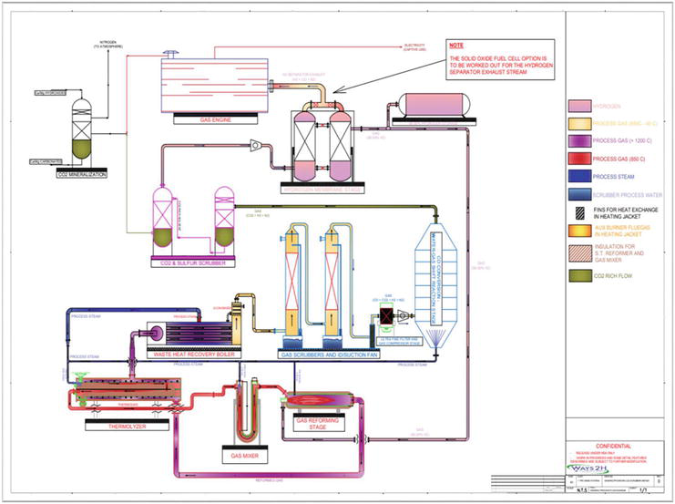
Figure 5.
Process flow diagram.
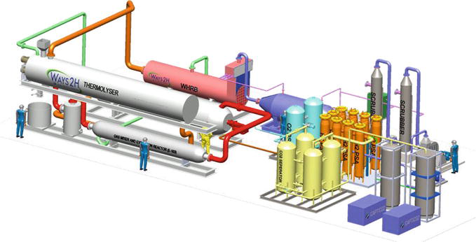
Figure 6.
Plant layout.
References
1.Basu P. Biomass Gasification and Pyrolysis – Practical Design. Academic Press; 2010. pp. 1-5
2.Bundschuh J. Technologies for Converting Biomass to Useful Energy. Vol. 4. Toowoomba, Australia: University of Southern Queensland (USQ); 2013. p. 10
3.Sharma S, Sheth PN. Air–steam biomass gasification: Experiments, modeling and simulation. Energy Conversion and Management. 2016;110:307-318
4.Ismail TM, El-Salam MA. Parametric studies on biomass gasification process on updraft gasifier high temperature air gasification. Applied Thermal Engineering. 2017;112:1460-1473
5.Mazaheri N. Modeling the Gasification Process of Wood-Char Biomass. Ste-Anne-de-Bellevue, QC, Canada: Department of Bioresource Engineering, McGill University; 2018. pp. 7-10
6.Ways2H [Internet]. Available from: http://www.ways2h.com [Accessed: January 11, 2024]
7.World Bank. State and Trends of Carbon Pricing 2021. Washington, DC: World Bank; 2021. Available from: http://hdl.handle.net/10986/35620
Written By
Jean-Louis Kindler and Hardik Y. Desai
Submitted: 02 August 2023Reviewed: 17 August 2023Published: 28 February 2024
 Open access peer-reviewed chapter