 Open access peer-reviewed chapter
Abstract
The concept of Augmented Reality (AR) has existed in the field of aerospace for several decades in the form of Head-Up Display (HUD) or Head-Worn Display (HWD). These displays enhance Human-Machine Interfaces and Interactions (HMI2) and allow pilots to visualize the minimum required flight information while seeing the physical environment through a semi-transparent visor. Numerous research studies are still being conducted to improve pilot safety during challenging situations, especially during low visibility conditions and landing scenarios. Besides flight navigation, aerospace engineers are exploring many modern cloud-based AR systems to be used as remote and/or AI-powered assist tools for field operators, such as maintenance technicians, manufacturing operators, and Air Traffic Control Officers (ATCO). Thanks to the rapid advancement in computer vision and deep neural network architectures, modern AR technologies can also scan or reconstruct the 3D environment with high precision in real time. This feature typically utilizes the depth cameras onboard or independent from the AR devices, helping engineers rapidly identify problems during an inspection and implement the appropriate solutions. Some studies also suggest 3D printing of reconstructed models for additive manufacturing. This chapter covers several aspects and potentials of AR technology in the aerospace sector, including those already adopted by the companies and those currently under research.
Keywords
- augmented reality (AR)
- modern technology
- aerospace engineering
- human-machine Interface (HMI)
- flight navigation
1. Introduction
Augmented Reality (AR) technology has had one of the most significant impacts in the aerospace sector. Caudell and Mizell [1] first coined the term “Augmented Reality” to explain an optical see-through head-mounted display that superimposed and anchored computer-generated graphics in an aircraft manufacturing plant. The technology would track the user’s head pose and place a Computer Aided Design (CAD) or other relevant information in a simplified format augmented over the user’s visual field of the real world, hence naming it “Augmented Reality.” While the name only existed three decades ago, the concept of AR existed long before then. Both aircraft Head-Up Display (HUD) and Head-Worn Display (HWD) existed long before that. In this chapter, we attempt to discuss the evolution of these technologies slightly differently than several existing literatures [2, 3] but also provide information on how it is evolving particularly in the navigation, engineering, and design sectors.
2. Flight navigation
Today, flying an aircraft depends on three factors: the machine, the controls, and instruments, and the human operator [4, 5]. The machine is what flies, and the human operator (i.e., pilot) is the one that flies the machine. But, without the proper controls and instrumentation, pilots would have no clue how or which direction to fly the aircraft in. Of course, the first powered aircraft by the Wright Brothers, the 1903 Wright Flyer that flew in Kitty Hawk, North Carolina, did not have any instruments to guide the pilots of such information [6]. Instead, the person on the ground would use a stopwatch, an anemometer, and an engine revolutions counter to calculate distance flown, speed, and horsepower of the propeller engine. Following the Wright Brother’s invention, many would continue to fly the aircraft. However, without proper instrumentation, many pilots would lose their lives because of structural failure or stalling, leading to the implementation of the first visual indicators in 1907. Pilots would be trained to fly the Wright aircraft using an incidence indicator consisting of two limiting red marks on the scale to identify the relative pitch of the aircraft [5]. Mechanical displays would continue to evolve for the next 5–6 decades followed by the electromechanical displays between 1930s and 1970s, and then by the first and second generations of Electronic Flight Instrument System (EFIS) [7]. Mechanical displays were pressure-based instruments and would often result in slower than required indication of various flight parameters. Unlike them, the electromechanical instruments would be electrically powered while the indications would still be driven pneumatically [8]. After decades of research within civil and military aviation, a standard arrangement of various instruments was developed which is still used in old aircraft today. While such displays provided more stable and accurate data for pilots during flight, the need to have more information for better situational awareness would lead to the need to requiring more eyes on the flight deck, resulting in the development and evolution of the EFIS. EFIS is a purely digital display system that receives its data through the onboard flight computer which receives its data from the onboard sensors. The newer generation of EFIS, referred to as the glass cockpit, uses a standard set of display units including a Primary Flight Display (PFD), a Navigational Display (ND), an Engine Indicating and Crew Alerting System (EICAS), or an Electronic Centralized Aircraft Monitor (ECAM), a Multifunctional Display (MFD), and a Flight Management Computer (FMC) [9, 10].
Much like the evolution of HDDs, the first recorded usage of a HUD dates to the 1920s, used as a reflector gunsight in a fighter aircraft by Sir Howard Grubb. His design was important because the gunsight would project a distant virtual image of a back illuminated aiming graticule such that the graticule could be superimposed over the distant target. For a typical gunsight back then, the gunman would have to align the target with a backsight and a foresight. That said, it was not until the 1940s that a dynamic visual component would be added to a reflector gunsight. Maurice Hancock designed this gyroscopic gunsight and used it on the RAF Spitfire and Hurricanes. For his invention, he used two independent sights: one was a version of Grubb’s sight, and the second was an aiming symbol that shifted across the line of sight by an angle that changed based on aircraft speed, altitude, attitude, and turn rate [9, 11]. Following this important feat, military aircraft in the 1950s and 1960s would begin displaying other flight-related details such as flight path vector into the displays. In 1962, a British strike aircraft named the Blackburn Buccaneer would be the first aircraft to have a fully operational HUD [2, 12]. By the 1970s, HUDs would start being used in commercial aircraft, starting with Sextant Avionique in the Dassault Mercure aircraft in 1975, shortly followed by Sundstrand and Douglas in their MD80 series aircraft. Once the technology hit the commercial market, HUDs were prioritized for safe landing and low visibility operations. By the early 2000s, HUD-equipped commercial aircraft had logged over 6 million flight hours with 30 thousand low visibility operations [13]. In 2009, the Flight Safety Foundation (FSF) released a report stating that the Head-Up Guidance System Technology (HGST) prevented about 38 percent overall potential accidents and 69 percent overall accidents caused during take-off or landing [13, 14]. Today, almost all the airlines and business jet aircraft are equipped with an HUD system. The evolution of HUD and VR would later inspire the invention of the Sword of Damocles by Ivan Edward Sutherland in 1968 [15], and the development of the Visually Coupled Airborne Systems Simulator (VCASS) [16] and the Super Cockpit Program [17, 18], both led by Thomas A. Furness III between 1960s and 1980s. Their work would inspire the military to consider the usage of Helmet Mounted Displays (HMDs) to be able to always visualize minimum flight and combat information during the flight.
2.1 Head-up display (HUD)
A HUD is comprised of two components: a Pilot Display Unit (PDU), and a HUD computer [13]. The PDU is simply a semi-transparent visor that is situated in the glareshield or above the pilot’s head. The HUD computer generates an image based on the flight information which is then reflected onto the PDU through a projector connected to the computer. To ensure visibility throughout the various stages of flight, the displayed contents are usually either monochrome green or a combination of monochrome green and magenta. The combiner glass on the PDU is specially coated so that only the color of light projected from the image source is visible to the pilot.
The main purpose of a HUD is to superimpose imagery over the pilot’s forward Field of View (FOV) outside the window [19]. In doing so, it reduces the amount of time pilots would have to focus on the HDD, especially during landing or low visibility conditions. HUD contents are being collimated on the visor which means the light rays are traveling parallel with the eye resulting in an infinite visual. Hence, the focus of the eyes would not need to be readjusted when transitioning between the display and the OTW. Lastly, the HUD’s graphical contents are generated digitally. Hence, some modified components of the imagery can be conformed with what the visuals are trying to represent. For instance, in a taxiway, HUD can be adjusted to overlay conformed representation of the horizon line as seen on the OTW from the pilot’s point of view as seen in Figure 1. Or it could be used to display advanced symbologies such as the Tunnel-in-the-Sky (TS) visual as later shown for a conceptual Urban Air Mobility (UAM) simulation in Figure 2.

Figure 1.
C-130 j HUD [

Figure 2.
The next generation of UAM AR-based cockpit (a) HUD view for UAM pilot’s point of view on a transparent AR screen (b) HUD view for using Microsoft HoloLens 2 to proof the concept of the UAM flight corridors [
2.2 Helmet mounted Display (HMD)
When using the HUD, it is assumed that the pilot only needs to focus on his/her forward FOV. As shown in Figure 3, HUD’s total FOV is much smaller than that of the HMD’s. This is mainly because the HUD’s total FOV is often the same as its instantaneous FOV as the pilot is assumed to be focusing only on the HUD. On the contrary, HMDs are equipped with the head tracking feature allowing the pilots to move around. Hence, their total FOV is much larger than their instantaneous FOV [22].

Figure 3.
HUD versus HMD: FOV [
Although HMDs tend to provide better SA around the aircraft during flights, they are often prone to pilot discomforts. Imagine a pilot flying an aircraft with a HUD while only looking in one direction. Now, imagine the same pilot flying the same aircraft with an HMD while trying to look in the same direction. Since the HMD is locked to the pilot’s head directly, his/her head also needs to be rigid, which is a difficult task for any living being. As a result, HMDs (similar to the Thales TopOwl HMD shown in Figure 4) are equipped only in military aircraft and not on any commercial aircraft.

Figure 4.
Thales TopOwl HMD [
That said, many aerospace officials have begun to rely on modern AR Head-Worn Displays (HWDs) for research and training purposes. The new generation of AR and XR headsets such as Varjo XR-3, Microsoft HoloLens, Magic Leap 2, etc. is not only capable of generating extremely high-resolution visuals but also capable of generating spatially anchored data in the close-proximity environment (Figure 5). While these devices are not certified for in-field navigation purposes, these have proven to be a great tool for pilot training [25], simulation [26], and HMI testing purposes (Figure 6) [4].
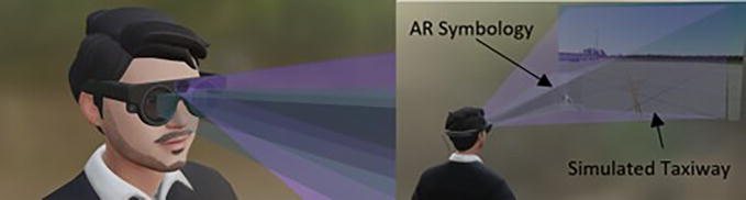
Figure 5.
Magic leap 2 AR headset being used for a potential application of airport surface navigation.

Figure 6.
Flight display testing using Microsoft HoloLens 1 [
2.3 Degraded visual environment (DVE)
In aviation, one of the most dominant factors of aircraft accident is the Degraded Visual Environment (DVE), similar to the one shown in Figure 7 [28]. A degraded visual condition is referred to as a state in which pilots experience partial or complete loss of visual cues, often due to fog, time of day, brownouts, whiteouts, or simply due to bad weather [29]. Flights during such situations often result in reduced Situational Awareness (SA). As will be discussed in the next couple of subsections, pilots heavily rely on visual cues to taxi, take-off, and land an aircraft or a rotorcraft. However, if they cannot see these cues, they need to rely on the instruments. These rules are categorized as Visual Flight Rules (VFR) and Instrument Flight Rules (IFR). One of the key problems with IFR during DVE conditions is that pilots can experience spatial disorientation between the Out-The-Window (OTW) visuals and what they see on the Head-Down Displays (HDD). Even for experienced pilots operating an aircraft or a rotorcraft via IFR can be challenging. More often than not, a small fault in the instrument can also lead to a disaster as described in [30]. One way to mitigate this problem is to utilize the AR technology to overlay the runway or taxiway information along with relevant terrain data to increase the pilot’s awareness. Moreover, a combination of these symbologies along with a properly crafted SVS can help pilots operate in VFR conditions even in a DVE state [31, 32].

Figure 7.
DVE caused during helicopter landing on desert [
2.4 Vision systems
As mentioned in the previous section, in a DVE condition, while protocol dictates pilots to follow IFR when operating an aerial vehicle in relation to the ground, pilots can occasionally experience spatial disorientation resulting in potential accidents. To prevent this, HUDs and HWDs are often equipped with various vision system technologies. In aviation, the three most common systems include: Enhanced Vision, Synthetic Vision, and Combined Vision [13].
2.4.1 Enhanced vision system (EVS)
EVS, or Enhanced Flight Vision System (EFVS), uses onboard sensors and light emitters to improve the visibility of the OTW environment. These sensors or emitters could include a Forward-Looking Infrared (FLIR) sensor, a millimeter wave radar scanner, a millimeter wave radiometer camera, or a set of Ultraviolet (UV) sensors. Besides the typical flight information, EFVS data are presented in the HUD or HMD via an analog or a digital video format as recorded from front of the aircraft with the visibility enhancements. Since EFVS is basically using standard physical equipment to improve the visibility, it is not supported for all environmental conditions and poses a limit to how helpful it could be when used with a HUD or an HWD [11, 12].
2.4.2 Synthetic vision system (SVS)
Unlike EFVS, SVS uses a 3D rendering tool to generate surrounding terrain models using databases based on the Global Navigation Satellite System (GNSS) data for position, heading, and elevation data. Since the data is generated separately, similar to developing scenes on 3D development platforms, any geolocated features such as airport markers, obstacles, or runway features can be conformed onto the virtual terrain architecture. Moreover, since the terrain model is generated based on available data, it can be used in all weather conditions [13, 33, 34].
2.4.3 Combined vision system (CVS)
As the name suggests, CVS combines the details captured from the real-world view in the EFVS and superimposes them onto the models generated for the SVS. It allows for a selective blending between the two technologies while providing real-time synthetic data, resulting in potentially better situational awareness than either of the previous systems [22, 35].
2.5 Surface navigation
One of the most challenging aspects of aircraft navigation is taxiing it along the airport taxiway [36]. Especially for large aircraft, pilots must be able to ride the aircraft while following the taxiway centerlines precisely. Traditionally, pilots rely on verbal communication with the Air Traffic Control Officers (ATCOs) and taxi charts. Airport taxiways and runways are often equipped with a collection of pavement markings and designation signs. Both ATCOs and taxi charts make references to these markings and signs allowing pilots to follow the taxiway and runway prior to take-off or after landing. Besides these two, most aircraft are also equipped with Electronic Moving Maps (EMM) or Onboard Aircraft Navigation System (OANS) to assist pilots taxi more efficiently [37]. Despite some infrastructure built to enhance their capability to taxi the aircraft, a single miscommunication between the pilots and ATCOs, or their (pilots’) misinterpretation of the taxi charts or maps can cause mild to fatal damage to the aircraft, its crew, and passengers, as reported in [38]. One way to minimize such incidents or accidents on the airport taxiways and runways is to use AR technology.
In 1996, David C. Foyle, et al. [39] introduced a HUD symbology configuration consisting of scene-linked 3D symbologies for taxiway centerlines and traffic edge cones and 2D symbologies for additional textual information such as Ground Speed (GS). These symbologies were designed to provide additional support to the pilots while minimizing their need to divert their attention to other visual contexts for the task and improve overall Situational Awareness (SA). Between 1996 and 2010, Foyle, Andre, and Hooey would lead multiple improvements on the design, focused on different aspects of the design such as importance of different types of information, or automated versus manual display of HUD components during a simulated flight.
One of the biggest challenges with surface flight operations using a HUD is that implementing head tracking is extremely complex as the scene-linked visual markers need to be relatively conformal to what they are representing. The simplest solution to this problem is to use a Head-Worn Display (HWD). Arthur et al. [40, 41, 42] led this area of research and implementation following the T-NASA study. Their concept for Beyond-RVR would allow them to view the scene-linked symbologies within a certain distance while still providing other flight information even if the pilots were to move their head around. An example of a similar concept is provided in Figure 8.

Figure 8.
T-NASA display on a HUD [
2.6 Air traffic control (ATC)
Potential avenues to enhance airport operations through the use of mixed reality have been proposed for decades, with a particular focus on air traffic control (ATC). This section will serve to highlight some of the noteworthy progress made in establishing a framework for mixed reality integration into ATC operations. In 2006, Reisman and Brown published a paper detailing the design of a prototype for augmented reality tools to be used in ATC towers. The Augmented Reality Tower Tool (ARTT) consisted of two phases; a prototype development and evaluation phase followed by an engineering prototype that resulted in the creation of a head-mounted display that superimposed simulated 3D images of runways, significant landmarks, and ATC data for the user to view and utilize to make decisions [43]. The system received mostly positive feedback from the ATC operators regarding its usefulness in a variety of tasks, including instances where coordination with aircraft under multiple low visibility scenarios was required. Another paper to note is Masotti’s work on designing and developing a framework to prototype AR tools specifically for ATC tower operations [44]. Using augmented reality, Masotti proposed several benefits that included a reduction in the amount of visual scanning required and an increase in situation awareness due to the relevant information being superimposed on the real-world view for the ATC operators in an organized manner. AR tools implemented in low visibility conditions aided in increasing situation awareness for operators and allowed for less time to be spent analyzing head-down operations.
Safi and Chung [3] provide a detailed exploration of AR applications and their uses in aerospace and aviation. Their chapter discusses the benefits and drawbacks of integrating AR into ATC operations. They also highlight the contrast between head-up and head-mounted displays (HUD and HMD respectively). While HUDs provide a larger field of view (FOV) and reduce computer processing lag through their direct connection to the terminals in the ATC tower, the lack of motion tracking capability and information only being accessible on these see-through displays limits the freedom of the ATC operator to move around and reduces their immersion. By contrast, HMDs solve these drawbacks but suffer with their limited FOV and discomfort during extended periods of wearing the HMD due to its weight. Moruzzi et al. have proposed the design and implementation of eye tracking application on a see-through display [45], with the goal being to achieve the concept of a Remote and Virtual Control Tower (RVT). Depending on the movement of each eye, digital content would then be overlaid onto the display where it would be the most appropriate and convenient for the user to view. Using a Microsoft Kinect device, the location of the eye on a human face was able to be distinguished and an algorithm tracked the motion of each user’s eye to then determine the placement of digital information to be superimposed on the screen.
2.7 Urban air mobility (UAM)
Recent developments, particularly regarding electric propulsion and battery storage, have led to flying vehicle concepts for personal usage [46, 47, 48]. Urban Air Mobility (UAM) is the new air transport system that uses low-mid level urban airspace below ~2000 ft. UAM is a subset of the Advanced Air Mobility (AAM) under development by NASA, FAA, and industry [16, 17]. UAM focuses on the urban and suburban environments [49].
Currently, the main challenges UAM is facing are community acceptance, safety concerns, airspace management, and required advances in ATC and autonomy. And many companies such as Airbus/Boeing/Honeywell even organizations like NASA, EASA, and ICAO are involved to speed up the development and acceptance of UAM in modern countries. Considering the growing interest in AR technology, rapid growth of UAM industry requires the incorporation of AR. Accordingly, instead of dealing with the physical controls, everything will be digital and imaginary, and flight mechanics and dynamics of the aircraft will be shown on the AR screen using the concepts of Human-Machine Interfaces and Interactions (HMI2) through symbology design while projecting the orientation and position of the UAM aircraft. Furthermore, using this new technology, the required time to train UAM pilots will significantly drop compared to the existing technologies, as the integrated AR system could be used from start to finish to train the pilots.
UAM needs to be easily, safely, and semi-automatically operated to be accepted by the public. Accordingly, three major areas could be targeted including flight monitoring, operation, and training. Among these, particularly monitoring and operation of UAM aircraft could be enhanced by AR which will be discussed in the following.
The monitoring is mostly about the next generation of control tower concepts that would benefit from AR [45, 50, 51]. For the purpose, traffic visualization, predictable corridors, and automated mission management are the key aspects of semi-autonomous operation of UAM aircraft. All information related to the flight, aircraft specifications, weather data, and safety of the airspace and each air vehicle should be shown in real time on the AR windows and presented to the tower operator [52, 53, 54]. This will also be part of the tasks that are defined for the Providers of Services for UAM (PSU) that are responsible for the operations planning, flight intent sharing, airspace management functions, off-nominal operations, operations optimization, and airspace reservations [55, 56]. Figure 9 presents the new AR-based ATC system using a transparent AR screen for UAM flight monitor in an urban environment [57].
Advances in Airspace Management and Automation for UAM operation are must due to safety concerns. The operation of UAM aircraft can also benefit from AR-based cockpits to modernize flight corridors according to the safety concerns and risk evaluation methods, augment the flight by auto-generation of new routes, and approve the new route before execution, use optimized flight path where autonomously adapt flight considering weather conditions and other aircraft, train, and obstacles (Figure 2) [21].

Figure 9.
View from the next generation of UAM control tower concepts that will be using AR windows [
3. Engineering operations
AR-based instructions are a series of visual information to guide users through an assembly process for complex engineering products [58, 59]. Due to the technological enhancements and the highly competitive engineering environment, innovative products are required to be taken into the market in a short period of time. This also demands a collaborative manufacturing environment to exchange real-time information [60]. Nowadays, thanks to the efforts of Airbus, Boeing, Bombardier, Safran, and Siemens, the new technology has been successfully applied in design, manufacturing, assembly, Maintenance, Repair, and Overhaul (MRO), and education. In this section, AR usage for design and assembly, collaborative interface, Artificial Intelligence (AI) and Machine Learning (ML) implementations, haptic integration, and computer vision implementations are discussed (Figure 10).

Figure 10.
Airbus uses immersive collaboration concept for cabin definition [
3.1 Design and assembly
Descriptive assembly instructions for complex procedures are a key factor to ensure a smooth assembly [62]. AR presents information in the cyber-physical space in the form of virtual models [63] and interacts with the actual assembly parts [64]. The application of assembly instructions has changed from just providing assembly procedures to actively providing heuristic visual guidance to meet operators’ cognitive requirements [65].
AR assembly has several benefits in enhancing the efficiency of manual assembly process. It mixes digital instructions and physical tasks. First, AR-based instructions extend the user’s visual understanding from the actual world to the information space [66]. Engineers can communicate with actual objects in cyber-physical space using interactive tools [67]. This communication constantly improves the user’s understanding of the actual model and deepens the usability and reliability of assembly procedures [68]. Secondly, compared to conventional assembly instructions, AR assembly instruction embeds interactive virtual instructions into the actual environment, enriching engineer’s experience of the actual world [69]. Moreover, AR assembly instruction is economically efficient and straightforward to construct procedures. Data calculation is accomplished by the digital system and is only responsible for the construction and representation of the instruction materials [70]. Thirdly, the rule of engineer cognition exists which enhances the communication efficiency between engineer and system [71, 72]. Earlier assembly instruction materials include paper-based manuals and drawings, recorded videos, simulation animations, etc. Figure 11 shows a graphical representation of the traditional assembly procedures in aerospace industries using physical manuals. Engineers usually experience a very time-consuming procedure, and the cognitive productivity is so low.
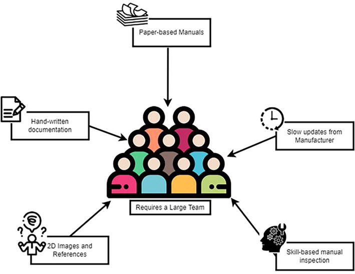
Figure 11.
Graphical representation of traditional assembly procedure in aerospace industries.
Nevertheless, the AR assembly instruction can enhance the interpretation of the engineer’s operations perspective. Finally, compared to traditional manuals, AR-based assembly instructions have more natural, intuitive interactivity, and user performance [73]. Engineers can precisely collaborate with AR-based assembly instructions using bare-hand feedback [74]. These instructions are presented in a 2D graphics language, which combines two illustrations. The first depicts the real model which includes the part or assembly illustrated by its orthographic projection. The second illustration overlays instructions on the first using a standard-based language that defines dimensions, tolerances, and assembly details [75].
In 2003, to meet the requirements of 3D assembly instructions as a manufacturing source, the ASME Y14.41 standard was issued [76]. Hence, 2D engineering drawings are now permitted for engineering operations. Thanks to the development of digital assembly and design technology, information can be directly inserted into the CAD model to create a model-based definition (MBD) database [77], which includes 3D geometry and product dimensional tolerance, to achieve complete product illustration [78]. In 2001, for the first time, Boeing implemented enhanced digital manufacturing technology for the assembly process of aircraft cables [79]. Afterward, it applied digital commands to help the entire aircraft assembly line [80].
However, 3D AR assembly instructions still face some drawbacks. First, the spatial information reflected by 3D instructions could be confusing as the display of the blueprint is typically presented on a 2D display [81]. The engineer is required to continuously switch attention between the display and the actual task, which can distract the engineer and result in the failure of the task. Additionally, in the assembly process, the actual environment and the instructions in digital environment are totally separated [82]. Also, there are some challenges with the Host Controller Interface (HCI) mode of 3D assembly instructions. For instance, engineers regularly do not use their hands to directly manipulate the tasks but instead use 2D interfaces such as displays, mouse, and keyboard [83].
Figure 12 shows a graphical representation of the current assembly procedures in aerospace industries where tablet-based manuals are used along with cloud-based updates from manufacturers. Cloud-based assembly platform provides flexible, high-performance, and universal capabilities. It works with big data to support communication, share data, and answer engineer questions through information provided by the manufacturer and reliable sources [84, 85].

Figure 12.
Graphical representation of current assembly procedure in aerospace industries.
3.2 AI and ML implementation
Boeing 777 was the first aircraft that was designed entirely from simulation without a physical mock-up. Likewise, ML and AI algorithms are playing a great role in the future of Aerospace design and assembly [86, 87, 88, 89, 90]. According to the study accomplished by Zhiwu AIoT Industry Research Institute, the Industrial Metaverse is a new ecosystem in which new information and communication technologies represented by the Internet of Things (IOT), AI, and digital twins are deeply integrated with the real economy [91].
ML is a growing set of optimization algorithms and regression methods to create models from data [86, 87, 88, 89, 90, 91, 92]. AI relies on the ability of computing to repeat human learning. It starts with mimicry by feeding large quantities of data to a network of neurons. It continues developing the network up until it can regenerate human abilities for reflection. In the next step, AI identifies responses in model data, images, synthesize information, predict trends, and present precise findings [93].
Each phase of advanced aerospace manufacturing is data-intensive, including design and assembly, testing, and service. A Boeing 787 contains millions of parts and subparts that are manufactured from around the world and assembled in an enormously complex manufacturing procedure. This results in massive multimodal information from supply chain logs, videos, inspection data, engineering drawings, and notes. After design and assembly, a single flight test will collect information from hundreds of thousands of multimodal sensors. In service as well, the aircraft creates numerous real-time data, which is collected, transferred, and processed with kilometers of wire and millions of code lines. Hence, big data is a reality in aerospace engineering and advanced data analytics with AI and ML is a must [87].
3.3 Embedded AR-assisted training
Haptic feedback would allow the engineer to directly perceive the data about the environment using the sense of touch [94, 95]. The term “Haptics” was proposed by Resvez in 1950 after observing a blind performance. The term refers to an unconventional sensory experience, deviating from traditional methods of touch and kinesthetics [96]. Haptic feedback is an alternative visual representation triggering condition. Haptic AR potentially overcomes the existing visual issues of AR allowing the user to focus on the task and avoid over-reliance on the technology [97].
Figure 13 graphically represents the concept of Haptic AI-assisted AR-based engineering operations in aerospace industries. The expected core technology instruction is as follows [98]:
Virtual-real interactive environment: The concept is supported by a semi-immersive virtual-real interactive space, which stimulates engineers’ learning capacities. This allows aerospace engineers to feel all work types in the physical space and virtual world simultaneously, to allow full use of the surrounding real objects as communication/interaction elements to accomplish manual tasks.
Spatial relation rendering: To make AI-assisted AR-based engineering operations more realistic, the consistency between virtual objects and actual space should be clarified. This is about the consistency of the actual environment in geometric aspects such as position, perspective, and occlusion.
Physical cue rendering: Lighting consistency is a crucial element in ideal combination of AR-based environment and physical scenes. Based on the light distribution in the actual scene, shadow processing is completed on AR commands to compensate the floating sense of command material in vision. In a sense, human eyes have strong feedback clues. If the light does not match the actual scene, the engineer instantly feels that.
Cognitive cue rendering: To effectively accomplish the manual tasks, the instruction reflected in AR must be related to the engineer’s cognition. The engineer must understand the intent of a physical process using the information provided in the AR-based instructions. In this process, assembly instructions are passed between the designer (or AI) and the engineer until an agreement is reached. Therefore, intention consistency is the most core feature of AI-assisted AR-based engineering operations.

Figure 13.
Graphical representation of next generation of AR-based engineering operations in aerospace industries.
3.4 Computer vision implementations
Computer vision is a field of artificial intelligence (AI) that trains a computer to extract information from images or video data. It involves the development of algorithms, techniques, and methodologies that enable computers to analyze, interpret, and understand visual data [99]. Computer vision algorithms support several use cases in aerospace engineering applications. For example, it can be used in quality control to inspect components, identify defects, and ensure adherence to quality specifications. Or, combined with AR technologies, can be used to develop training tools to provide real-time overlays of information, instructions, or virtual representations to guide the user through an assembly process.
One of the most common use cases of computer vision is in aircraft MRO for visual inspection. Using deep learning algorithms, technicians can scan the surface of an aircraft to identify potential maintenance issues. The convolutional neural network (CNN) provides the means to accomplish this. A CNN is a supervised deep learning model that is used for image classification. Supervised learning is a training strategy where a model is taught how to make predictions based on labeled examples. In this method, the model is provided with a set of input data, along with the correct answer or outcomes associated with that data. For image classification, the model extracts relevant features or patterns from images, which can include edges, textures, shapes, colors, and other visual characteristics. These are used to make predictions on new examples. There are various types of CNN architectures that exist, and it is the most common computer vision solution used in aerospace for a variety of applications [99].
A CNN is a supervised deep learning model that is used for image classification. Supervised learning is a training strategy where a model is taught how to make predictions based on labeled examples. In this method, the model is provided with a set of input data, along with the correct answer or outcomes associated with that data. For image classification, the model extracts relevant features or patterns from images, which can include edges, textures, shapes, colors, and other visual characteristics. These are used to make predictions on new examples. There are various types of CNN architectures that exist, and it is the most common computer vision solution used in aerospace for a variety of applications.
Identification of fuselage defects and visual checks are commonly addressed topics in the aircraft inspection literature. Autonomous visual inspection of an aircraft exterior is possible using drones and a high-resolution camera [100]. In 2021 German aerospace company, Lufthansa Technik trained a deep neural network to identify fuselage defects (i.e., dents, scratches) at the Lufthansa Technik summit. This was accomplished by capturing high-resolution photos of the aircraft exterior using a drone along path outlined in Figure 14. The snake-like pattern pans both sides and the nose of the plane, while the roof of the aircraft is captured using a downward-facing camera [102]. The captured images are sent to a computer for data processing and identification of damages and irregularities [100]. Generating sufficient examples to adequately train a neural network was the biggest hurdle identified by Lufthansa, as there are no public datasets available for damage samples. Moreover, it is expensive and laborious to create their own training material. So, the neural network was trained on a synthetic dataset. The aircraft was simulated virtually where the hangar lighting, time of day, and placement of defects on the simulated aircraft are adjusted to generate a sufficient training dataset [102]. The resulting model yielded a detection accuracy above 95%, in the simulated environment with a dataset size of 4000 images.

Figure 14.
Simulated drone path [
A robust computer vision application depends largely on the quality and quantity of training data. Boeing used a computer vision approach to develop an AR application for aircraft inspection. The application would overlay markers atop the aircraft identifying points of existing damage marked by other mechanics. To accomplish this, the application needed to anchor a 3D virtual model on top of the aircraft as seen by the mechanic through the AR device. Boeing used a machine learning approach to solve this problem, generating their own dataset consisting of thousands of images of aircraft from different perspectives. Using a pose estimation algorithm, and a series of markers placed around the aircraft, the aircraft’s position was calculated in relation to the camera. The machine learning model was fed this data to calculate the position of the aircraft based on the images coming from the camera without markers. Due to the small dataset size, the model performed poorly. And, like Lufthansa Technik, Boeing showed that using field data to train their machine learning model was ineffective due to the laborious nature of acquiring data [103].
Another example of innovative computer vision implementations in aerospace is the Airbus Wayfinder Project. The project was initiated by Airbus in June 2018 in collaboration with Project Wayfinder with the ambition to revolutionize autonomous flight [104]. The objective of this project was to achieve autonomous taxiing, take-off, and landing (ATTOL) of a commercial aircraft through a computer vision-based system. Although commercial aircraft can already fly an approach, land, and rollout to taxi without pilot input, this is only possible on runways equipped with a CAT III ILS. The installation and maintenance of this system is costly, and only a few airports can justify its cost. So, a deep learning model was used to teach an aircraft to fly an approach and landing sequence without any pilot input. The algorithm implements an object detection model to identify the runway, and a regression model to estimate the distance, localizer, and glide slope values of the aircraft [105]. A modified Single Shot Detection network (SSD) was used to accomplish this. The beginning layers of the SSD are used to extract features about the runway environment, while the ending layers are responsible for boxing the region containing the runway, distance to the runway, localizer deviation, and glideslope deviation. Like others, Airbus relied on synthetic data and developed a model that can reliably detect the runway from several miles away.
4. 3D reconstruction and visualization
3D reconstruction is the process of capturing the shape and appearance of real objects. 3D reconstruction can be accomplished by numerous methods. Single cameras are computationally efficient but require other sensors to determine depth scale. Stereo cameras utilize images captured from two cameras set a defined distance. An algorithm is used to evaluate the depth using the two images. Lastly, RGBD cameras, such as LiDAR, can perform range detection using structured light sensors to directly capture depth information [106].
In recent years, LiDAR technology has shown more applications with its capabilities for remote sensing and data acquisition. LiDAR technology provides a unique advantage over traditional remote sensing methods through high-resolution data acquisition with spatial and real-time capabilities. LiDAR sensors can construct detailed point clouds representing the shape, structure, and surface characteristics of objects and landscapes.
LiDAR technology has shown promising results for the inspection of airframes and aerodynamic surfaces [107]. The ability to capture highly detailed 3D representations of aircraft components and structures facilitates advanced inspection techniques. The traditional method of visual inspection, although common, has limitations in detecting these defects due to the lack of contrast and reflectance on most surfaces. Moreover, the reliance on human inspections and specialized equipment increases inspection time and cost significantly. By obtaining a 3D point cloud of the aircraft’s parts and comparing it with a reference CAD model, surface deformations can be detected. This comparison generates a disparity map that highlights the differences between the reference CAD model and the inspection point cloud. With current LiDAR technologies, reconstruction accuracies can be obtained with errors less than 1 millimeter.
3D reconstruction of the environment is another important use case in aerospace, primarily for analyzing terrain. With the advance of drone technology, practical applications of 3D reconstruction include the inspection and mapping of areas that are difficult to access by humans. For instance, the mapping of an accident site can be accomplished using a high-resolution camera and 3D reconstruction tools [108]. Using LiDAR technology, this is achieved by relating the RGB frame with its depth frame. The simultaneous localization and mapping algorithm, also known as SLAM, is one such method that builds a map of the environment while localizing the camera in the map at the same time [109]. SLAM allows aircraft to map out unknown environments, which is extremely useful to carry out tasks such as path planning and obstacle avoidance.
5. Conclusion
In conclusion, this chapter presented the current applications of AR in the field of aerospace, particularly in navigation and engineering. AR has been used in aerospace navigation for several decades in the form of HUD or HWD. These displays enhance HMI2 and allow pilots to navigate the aircraft flight. Besides navigation, aerospace engineers are exploring AR systems to be used as remote and/or AI-powered assist tools for field operators, such as MRO, design, and assembly and ATCO. AR technologies can also scan or reconstruct the 3D environment with high resolution in real time using computer vision and deep neural network architectures to allow engineers to rapidly identify problems during an inspection.
Acknowledgments
We would like to thank Niraj Karki and Charith Kongara for providing their knowledge and insights in ATC and Computer Vision, and thoroughly reviewing the drafts along the way.
References
- 1.
Caudell TP, Mizell DW. Augmented reality: An application of heads-up display technology to manual manufacturing processes. In: Proceedings of the Twenty-Fifth Hawaii International Conference on System Sciences. Vol. 2. Kauai, HI, USA: IEEE; 1992. pp. 659-669. DOI: 10.1109/HICSS.1992.183317 - 2.
Safi M, Chung J, Pradhan P. Review of augmented reality in aerospace industry. Aircraft Engineering and Aerospace Technology. 2019; 91 :1187-1194. DOI: 10.1108/AEAT-09-2018-0241 - 3.
Safi M, Chung J. Augmented reality uses and applications in aerospace and aviation. In: AYC N, Ong SK, editors. Springer Handb. Augment. Real. Cham: Springer International Publishing; 2023. pp. 473-494. DOI: 10.1007/978-3-030-67822-7_20 - 4.
Pradhan P. Augmented Reality Cockpit Display System in Real-Time Flight Simulation Environment [thesis]. Toronto, ON, Canada: Toronto Metropolitan University; 2023 [cited 2023 Jul 6]. DOI: 10.32920/23580471.v1 - 5.
Coombs LFE. Control in the Sky: The Evolution & History of the Aircraft Cockpit. Barnsley, SY, UK: Pen & Sword; 2005 - 6.
Wright Flyer. 1903 National Air and Space Museum n.d. Available from https://airandspace.si.edu/collection-objects/1903-wright-flyer/nasm_A19610048000 [accessed July 6, 2023] - 7.
Lim Y, Gardi A, Sabatini R, Ramasamy S, Kistan T, Ezer N, et al. Avionics human-machine interfaces and interactions for manned and unmanned aircraft. Progress in Aerospace Science. 2018; 102 :1-46. DOI: 10.1016/j.paerosci.2018.05.002 - 8.
Nicholl R. Airline Head-up Display Systems: Human Factors Considerations. Saarbrücken: LAP LAMBERT Academic Publishing; 2015 - 9.
Federal Aviation Association. FAA-H-8083-15B, Instrument Flying Handbook. Oklahoma City, OK, USA: United States Department of Transportation; 2012. Available from: https://www.faa.gov/sites/faa.gov/files/regulations_policies/handbooks_manuals/aviation/FAA-H-8083-15B.pdf - 10.
Jarrett DN. Cockpit Engineering. Aldershot, Hampshire, England. Burlington, VT: Ashgate; 2005 - 11.
Aukstakalnis S. Practical Augmented Reality: A Guide to the Technologies, Applications, and Human Factors for AR and VR. Boston: Addison-Wesley Professional; 2017 - 12.
Nijboer D. Fighting Cockpits: In the Pilot’s Seat of Great Military Aircraft from World War I to Today. Minneapolis, MN, USA: Zenith Press; 2016 [cited 2023 Jul 6]. Available from: http://archive.org/details/fightingcockpits0000nijb - 13.
Wood RB, Howells PJ. Head-Up Display. In: Spitzer CR, Ferrell U, Ferrell T, editors. Digital Avionics Handbook. 3rd ed. Bowie, MD, USA: CRC Press, Taylor & Francis Group; 2015. pp. 17-1-17-27 - 14.
Head-Up Guidance System Technology — A Clear Path to Increasing Flight Safety n.d.:29 - 15.
Sutherland IE. A head-mounted three dimensional display. In: Proc. Dec. 9-11 1968 Fall Jt. Comput. Conf. Part - AFIPS 68 Fall Part I. San Francisco, California: ACM Press; 1968. p. 757. DOI: 10.1145/1476589.1476686 - 16.
A visually-coupled airborne systems simulator (VCASS) - An approach to visual simulation. n.d. - 17.
Livingston MA, Rosenblum LJ, Brown DG, Schmidt GS, Julier SJ, Baillot Y, et al. Military applications of augmented reality. In: Furht B, editor. Handb. Augment. Real. New York, NY: Springer New York; 2011. pp. 671-706. DOI: 10.1007/978-1-4614-0064-6_31 - 18.
Furness TA. The super cockpit and its human factors challenges. Proc Hum Factors Soc Annu Meet. 1986; 30 :48-52. DOI: 10.1177/154193128603000112 - 19.
Wickens CD, Ververs PM, Fadden S. Head-up displays. In: Harris D, editor. Human Factors for Civil Flight Deck Design. 1st Ed. Oxfordshire, UK: Routledge; 2004. DOI: 10.4324/9781315253039 - 20.
Logistics T. English: C-130J: Co-pilot’s Head-Up Display. California: Former Castle AFB; 2005 - 21.
Rostami M. Development of an Extended Reality Based Flight Simulator for Urban Air Mobility. Conference presentation presented at: SETP Canadian Section Symposium; Ottawa, ON, Canada; May 2023 - 22.
Collinson RPG. Displays and man–machine interaction. In: RPG C, editor. Introd. Avion. Syst. Dordrecht: Springer Netherlands; 2011. pp. 19-99. DOI: 10.1007/978-94-007-0708-5_2 - 23.
Tiraden Français. Viseur de casque Topowl de la société Thales. commandé par plusieurs pays dont l’armée de terre française pour les pilote de l’Eurocopter Tiger. Photo prise au salon du Bourget 2017. 2017. - 24.
TopOwl. Helmet-mounted Sight & Display for Helicopters. Thales Group. n.d. Available from: https://www.thalesgroup.com/en/markets/aerospace/flight-deck-avionics-equipment-functions/helmet-mounted-display/TopOwl [accessed July 6, 2023] - 25.
Arjoni DH, de Souza RI, Pereira Figueira JM, Villani E. Augmented reality for training formation flights: An analysis of human factors. Heliyon. 2023; 9 :e14181. DOI: 10.1016/j.heliyon.2023.e14181 - 26.
Varjo. Virtual and Mixed Reality for Pilot Training and Simulation. Washington, DC, USA: Varjo; [cited 2023 Jul 6]. Available from: https://25667574.fs1.hubspotusercontent-eu1.net/hubfs/25667574/eBook%20and%20whitepaper%20PDFs/Varjo_Whitepaper_PilotTraining%20(1).pdf?utm_campaign=Content%20Downloads&utm_medium=email&_hsmi=63184198&_hsenc=p2ANqtz-92EGVID4937b3iqx8VWwKm2S360mbOHG-DXyjav3qMiJSI2xHkDpVEa--sNsy794JTC0Jx9WdgbqU5ogyMEg7T9dLeBdBcd525cVZCrdrbscZAaNw&utm_content=63184198&utm_source=hs_automation - 27.
KUWAIT – Lt. Caleb Wyman and Lt. Cmdr. Def Vis Inf Distrib Serv 2015. Aug. 19, 2015 Available from: https://nara.getarchive.net/media/kuwait-aug-19-2015-lt-caleb-wyman-and-lt-cmdr-aa76af [accessed July 6, 2023] - 28.
Szoboszlay Z, Miller J, Godfroy-Cooper M, Davis B, Feltman K, Hartnett RG, et al. The Design of Pilot Cueing for the Degraded Visual Environment Mitigation (DVE-M) System for Rotorcraft. In: Crew Stations and Human Factors [Online]. The Vertical Flight Society; 2021 [cited 2023 Jul 6]. Available from: https://vtol.org/store/product/the-design-of-pilot-cueing-for-the-degraded-visual-environment-mitigation-dvem-system-for-rotorcraft-16746.cfm - 29.
Chittaluri V. Development and Evaluation of Cueing Symbology for Rotorcraft Operations in Degraded Visual Environment (DVE). [thesis]. Toronto, ON, Canada: Toronto Metropolitan University; 2022 [cited 2023 Jul 6]. DOI: 10.32920/ryerson.14665293.v1 - 30.
Spatial Disorientation Accidents: IFR in IMC 2020. https://www.aopa.org/training-and-safety/online-learning/safety-spotlights/spatial-disorientation/spatial-disorientation-accidents-ifr-in-imc [accessed July 6, 2023] - 31.
Mubarak SNHF, Jacob AA. The impacts of advanced Avionics on degraded visual environments. International Journal of Aviation, Aeronautics, and Aerospace. 1 Jan 2023; 10 (1):1-12 [cited 2023 Jul 6]. DOI: 10.58940/2374-6793.1773 - 32.
Behringer R, Tam C, McGee J, Sundareswaran V, Vassiliou M. A System for Synthetic Vision and Augmented Reality in Future Flight Decks. In: Proceedings of the SPIE. Orlando, FL, USA: SPIE Aerospace; 2000. p. 81-86. DOI: 10.1117/12.389332 - 33.
Shelton KJ, Kramer LJ, Ellis K, Rehfeld DSA. Synthetic and enhanced vision systems for nextGen (SEVS) simulation and flight test performance evaluation. n.d. - 34.
Arthur JJ III, Prinzel LJ III, Kramer LJ, Parrish RV. Flight Simulator Evaluation of Synthetic Vision Display Concepts to Prevent Controlled Flight into Terrain (CFIT). Hampton, Virginia: NASA: Langley Research Center; 2004 - 35.
Kratchounova D, Newton D, United States. Department of Transportation. Federal Aviation Administration. Office of Aviation. Civil Aerospace Medical Institute. Combined Vision Systems Literature Review. 2019. - 36.
Hooey B, Foyle D, Andre A. A Human-centered methodology for the design, evaluation, and integration of cockpit displays. 2002 - 37.
Guilloton A, Arethens J-P, Avionics T, Macabiau C, Koenig D. State of the art in airport navigation. In: 2011 IEEEAIAA 30th Digit. Avion. Syst. Conf., Seattle, WA, USA: IEEE; 2011. pp. 4B3-1-4B3-11. DOI: 10.1109/DASC.2011.6096072 - 38.
NTSB Search Results [Internet]. Washington, DC, USA: FAA Aviation Safety Information Analysis and Sharing (ASIAS); [cited 2023 Jul 5]. Available from: https://www.asias.faa.gov/apex/f?p=100:27:::NO:27 - 39.
Foyle DC, Andre AD, McCann RS, Wenzel EM, Begault DR, Battiste V. Taxiway navigation and situation awareness (T-NASA) system: Problem, design philosophy, and description of an integrated Display suite for low-visibility airport surface operations. SAE Transactions. 1996; 105 :1411-1418 - 40.
Bailey RE, Shelton KJ, Arthur III JJ. Head-worn displays for NextGen. In: Marasco PL, Havig PR, editors. Head- and Helmet-Mounted Displays XVI: Design and Applications. Orlando, FL, United States: SPIE Digital Library; 2011. p. 80410G [cited 2023 Jul 5]. DOI: 10.1117/12.885847 - 41.
Trey, Jarvis AJ, Bailey RE, Williams SP, Prinzel LJ, Shelton KJ, Jones DR, et al. Review of head-worn displays for the next generation air transportation system. Optical Engineering. 2017; 56 :051405-051405. DOI: 10.1117/1.OE.56.5.051405 - 42.
Arthur JJ, Bailey RE, III Prinzel LJ, Kramer LJ, Williams SP. Multi-modal cockpit interface for improved airport surface operations. US7737867B2. 2010 - 43.
Reisman R, Brown D. Design of Augmented Reality Tools for air traffic control towers. In: 6th AIAA Aviat. Technol. Integr. Oper. Conf. American Institute of Aeronautics and Astronautics: ATIO, Wichita, Kansas; 2006. DOI: 10.2514/6.2006-7713 - 44.
Masotti N, De Crescenzio F, Bagassi S. Augmented reality in the control tower: A rendering pipeline for multiple head-tracked head-up displays. In: De Paolis LT, Mongelli A, editors. Augment. Real. Virtual Real. Comput. Graph. Cham: Springer International Publishing; 2016, p. 321-338. DOI: 10.1007/978-3-319-40621-3_23. - 45.
Moruzzi MC, Santhosh S, Corsi M, Bagassi S, De Crescenzio F. Design and implementation of eye tracking application for generation of augmented reality content on spatial see through display of remote and virtual control tower (RVT). International Journal on Interactive Design and Manufacturing (IJIDeM). 2023; 17 :1859-1867. DOI: 10.1007/s12008-023-01288-7 - 46.
Straubinger A, Rothfeld R, Shamiyeh M, Büchter K-D, Kaiser J, Plötner KO. An overview of current research and developments in urban air mobility – Setting the scene for UAM introduction. Journal of Air Transport Management. 2020; 87 :101852. DOI: 10.1016/j.jairtraman.2020.101852 - 47.
Kuhn H, Falter C, Sizmann A. Renewable Energy Perspectives for Aviation. 2011 - 48.
Rezende R, Barros J, Perez V. General Aviation 2025 - A study for electric propulsion. 2018. DOI: 10.2514/6.2018-4900 - 49.
Gipson L. Advanced Air Mobility (AAM). NASA. 2019. Available from: http://www.nasa.gov/aam [accessed July 5, 2023] - 50.
Bagassi S, De Crescenzio F, Lucchi F, Masotti N. Augmented and virtual reality in the airport control tower. 2016 - 51.
Gorbunov AL, Nechaev EE. Augmented reality Technologies in air Transport Control Systems. In: 2022 Systems of Signals Generating and Processing in the Field of on Board Communications. Moscow, Russia: IEEE; 2022. p. 1-5. DOI: 10.1109/IEEECONF53456.2022.9744399 - 52.
NASA Aeronautics Research Institute (NARI). NASA’s Advanced Air Mobility. NARI. n.d. Available from: https://nari.arc.nasa.gov/aam-portal/ [accessed July 5, 2023] - 53.
Hill BP, DeCarme D, Metcalfe M, Griffin C, Wiggins S, Metts C, et al. UAM Vision Concept of Operations (ConOps) UAM Maturity Level (UML) 4. Washington, DC, USA: NASA; 2020 Dec [cited 2023 Jul 5]. (NTRS - NASA Technical Reports Server). Report No.: 20205011091. Available from: https://ntrs.nasa.gov/citations/20205011091 - 54.
Bassey R. Vertiport Design. Washington, DC, USA: Federal Aviation Administration. Sep 2022 [cited 2023 Jul 5]. Report No: 105. Available from: https://www.faa.gov/sites/faa.gov/files/eb-105-vertiports.pdf - 55.
Fontaine P. Concept of Operations Version 2.0. Washington, DC, USA: Federal Aviation Administration; Apr 2023. [cited 2023 Jul 5]. (Urban Air Mobility (UAM)). Available from: https://www.faa.gov/sites/faa.gov/files/Urban%20Air%20Mobility%20%28UAM%29%20Concept%20of%20Operations%202.0_0.pdf - 56.
Gipson L. Advanced air mobility project. NASA 2020. http://www.nasa.gov/aeroresearch/programs/iasp/aam/description [accessed July 5, 2023] - 57.
Rostami M, Kamoonpuri J, Pradhan P, Bardin J, Oyama Y, Choe A, et al. Enhancing Urban Air Mobility Development Using Extended Reality Technology. Conference presentation presented at: Canada-Korea Conference on Science and Technology; Niagara Falls, ON, Canada; Jul 2022 - 58.
Wang Z, Zhang R, Lei Z, Descorme C, Wong M. New opportunities and challenges in energy and environmental catalysis (EEST2018). Catalysis Today. 2019; 339 . DOI: 10.1016/j.cattod.2019.08.001 - 59.
Wang Z, Bai X, Zhang S, Billinghurst M, He W, Wang Y, et al. The role of user-centered AR instruction in improving novice spatial cognition in a high-precision procedural task. Advanced Engineering Informatics. 2021; 47 :101250. DOI: 10.1016/j.aei.2021.101250 - 60.
Cohen Y, Naseraldin H, Chaudhuri A, Pilati F. Assembly systems in industry 4.0 era: A road map to understand assembly 4.0. International Journal of Advanced Manufacturing Technology. 2019; 105 :4037-4054. DOI: 10.1007/s00170-019-04203-1 - 61.
King H. Paris Air Show 2023: Airbus unveils immersive collaboration concept for cabin definition. FINN - Aviat Ind Hub FINN. 2023. Available from: https://www.wearefinn.com/topics/posts/pas-2023-airbus-unveils-immersive-collaboration-concept-for-cabin-definition/ [accessed July 5, 2023] - 62.
Yuan ML, Ong SK, Nee AYC. Assembly Guidance in Augmented Reality Environments Using a Virtual Interactive Tool. Queenstown, Singapore: Singapore-MIT Alliance (SMA); 2005 Jan [cited 2023 Jul 5]. (Innovation in Manufacturing Systems and Technology (IMST)). Available from: https://dspace.mit.edu/handle/1721.1/7442 - 63.
Liu C, Cao S, Tse W, Xu X. Augmented reality-assisted intelligent window for cyber-physical machine tools. Journal of Manufacturing Systems. 2017; 44 :280-286. DOI: 10.1016/j.jmsy.2017.04.008 - 64.
Zhou F, Duh HBL, Billinghurst M. Trends in augmented reality tracking, interaction and display: A review of ten years of ISMAR. In: 2008 7th IEEE/ACM International Symposium on Mixed and Augmented Reality. Cambridge: IEEE; 2008. pp. 193-202. DOI: 10.1109/ISMAR.2008.4637362 - 65.
Wang Z, Bai X, Zhang S, He W, Zhang X, Zhang L, et al. Information-level AR instruction: A novel assembly guidance information representation assisting user cognition. International Journal of Advanced Manufacturing Technology. 2020; 106 :603-626. DOI: 10.1007/s00170-019-04538-9 - 66.
Henderson SJ, Feiner SK. Augmented reality in the psychomotor phase of a procedural task. In: 2011 10th IEEE International Symposium on Mixed and Augmented Reality. Basel, Switzerland: IEEE; 2011. pp. 191-200. DOI: 10.1109/ISMAR.2011.6092386 - 67.
Syberfeldt A, Danielsson O, Holm M, Wang L. Visual assembling guidance using augmented reality. Procedia Manufacturing. 2015; 1 :98-109. DOI: 10.1016/j.promfg.2015.09.068 - 68.
Westerfield G, Mitrovic A, Billinghurst M. Intelligent augmented reality training for motherboard assembly. International Journal of Artificial Intelligence in Education. 2015; 25 :157-172. DOI: 10.1007/s40593-014-0032-x - 69.
Fiorentino M, Monno G, Uva AE. Tangible digital master for product lifecycle management in augmented reality. International Journal on Interactive Design and Manufacturing (IJIDeM). 2009; 3 :121-129. DOI: 10.1007/s12008-009-0062-z - 70.
Yuan M, Ong SK, Nee A. Augmented reality for assembly guidance using a virtual interactive tool. International Journal of Production Research. 2008; 46 :1745-1767. DOI: 10.1080/00207540600972935 - 71.
Wang X, Ong SK, Nee AYC. Multi-modal augmented-reality assembly guidance based on bare-hand interface. Advanced Engineering Informatics. 2016; 30 :406-421. DOI: 10.1016/j.aei.2016.05.004 - 72.
Wang Z, Bai X, Zhang S, Wang Y, Han S, Zhang X, et al. User-oriented AR assembly guideline: A new classification method of assembly instruction for user cognition. International Journal of Advanced Manufacturing Technology. 2021; 112 :41-59. DOI: 10.1007/s00170-020-06291-w - 73.
Büttner S, Mucha H, Funk M, Kosch T, Aehnelt M, Robert S, et al. The design space of augmented and virtual reality applications for assistive environments in manufacturing: A visual approach. In: Proc. 10th Int. Conf. PErvasive Technol. Relat. Assist. Environ. New York, NY, USA: Association for Computing Machinery; 2017. pp. 433-440. DOI: 10.1145/3056540.3076193 - 74.
Ong SK, Wang ZB. Augmented assembly technologies based on 3D bare-hand interaction. CIRP Annals. 2011; 60 :1-4. DOI: 10.1016/j.cirp.2011.03.001 - 75.
Dori D, Tombre K. From engineering drawings to 3D cad models: Are we ready now? Computer-Aided Design. 1995; 27 :243-254. DOI: 10.1016/0010-4485(95)91134-7 - 76.
Pilkaite T, Nenorta V. Digital product definition data practices. In: BALTGRAF Sel. Pap. Int. Conf. Eng. Graph. Vol. 12. Vilnius, Lithuania: Vilnius Gediminas Technical University, Department of Construction Economics & Property; 2013. pp. 171-176 - 77.
Alemanni M, Destefanis F, Vezzetti E. Model-based definition design in the product lifecycle management scenario. International Journal of Advanced Manufacturing Technology. 2011; 52 :1-14. DOI: 10.1007/s00170-010-2699-y - 78.
Liu F, Qiao LH. Product information Modeling and organization with MBD. Applied Mechanics and Materials. 2012; 163 :221-225. DOI: 10.4028/www.scientific.net/AMM.163.221 - 79.
Barfield W, Caudell T, editors. Boeing’s Wire Bundle Assembly Project. In: Fundamentals of Wearable Computers and Augmented Reality. 1st ed. Boca Raton: CRC Press; 2001. pp. 462-482 [cited 2023 Jul 5]. Available from: https://www.taylorfrancis.com/books/9780585383590/ DOI: 10.1201/9780585383590-21 - 80.
Sharma KJ, Bowonder B. The making of Boeing 777: A case study in concurrent engineering. International Journal of Manufacturing Technology and Management. 2004; 6 :254-264 - 81.
Shen Y, Ong SK, Nee AYC. Augmented reality for collaborative product design and development. Design Studies. 2010; 31 :118-145. DOI: 10.1016/j.destud.2009.11.001 - 82.
Nee AYC, Ong SK, Chryssolouris G, Mourtzis D. Augmented reality applications in design and manufacturing. CIRP Annals. 2012; 61 :657-679. DOI: 10.1016/j.cirp.2012.05.010 - 83.
Rekimoto J. Transvision: A hand-held augmented reality system for collaborative design. In: Proceedings of Virtual Systems and Multi-Media (VSMM ’96). Washington, DC, USA: IEEE Computer Society; 1996. DOI: 10.5555/846220 - 84.
Huang Z, Li W, Hui P, Peylo C. CloudRidAR: A cloud-based architecture for mobile augmented reality. In: Proc. 2014 Workshop Mob. Augment. Real. Robot. Technol.-Based Syst. New York, NY, USA: Association for Computing Machinery; 2014. pp. 29-34. DOI: 10.1145/2609829.2609832 - 85.
Mourtzis D, Zogopoulos V, Vlachou E. Augmented reality application to support remote maintenance as a Service in the Robotics Industry. Procedia CIRP. 2017; 63 :46-51. DOI: 10.1016/j.procir.2017.03.154 - 86.
Insaurralde CC. Artificial intelligence engineering for aerospace applications. In: 2020 AIAA/IEEE 39th Digital Avionics Systems Conference (DASC). San Antonio, TX, USA: IEEE; 2020. p. 1-7. DOI: 10.1109/DASC50938.2020.9256770 - 87.
Brunton SL, Nathan Kutz J, Manohar K, Aravkin AY, Morgansen K, Klemisch J, et al. Data-driven aerospace engineering: Reframing the industry with machine learning. AIAA Journal. 2021; 59 :2820-2847. DOI: 10.2514/1.J060131 - 88.
Jordan MI, Mitchell TM. Machine learning: Trends, perspectives, and prospects. Science. 2015; 349 :255-260. DOI: 10.1126/science.aaa8415 - 89.
Wu X, Kumar V, Ross Quinlan J, Ghosh J, Yang Q , Motoda H, et al. Top 10 algorithms in data mining. Knowledge and Information Systems. 2008; 14 :1-37. DOI: 10.1007/s10115-007-0114-2 - 90.
Lynch C. How do your data grow? Nature. 2008; 455 :28-29. DOI: 10.1038/455028a - 91.
Swart W. The Industrial Metaverse is “basically” a Digital Twin. Johannesburg, Gauteng, South Africa: 4 Sight; 2023 [cited 2023 Jul 5]. Available from: https://4sight.cloud/images/media/documents/01/785/metaverseblogpostwilhelmjanuary2022.pdf - 92.
Brunton SL, Kutz JN. Data-Driven Science and Engineering: Machine Learning, Dynamical Systems, and Control. Cambridge: Cambridge University Press; 2019 - 93.
Batra R, Song L, Ramprasad R. Emerging materials intelligence ecosystems propelled by machine learning. Nature Reviews Materials. 2021; 6 :655-678. DOI: 10.1038/s41578-020-00255-y - 94.
Lam TM, Boschloo HW, Mulder M, van Paassen MM. Artificial force field for haptic feedback in UAV teleoperation. IEEE Trans Syst Man Cybern - Part Syst Hum. 2009; 39 :1316-1330. DOI: 10.1109/TSMCA.2009.2028239 - 95.
Huang F, Gillespie RB, Kuo A. Haptic feedback and human performance in a dynamic task. In: Proceedings 10th Symposium on Haptic Interfaces for Virtual Environment and Teleoperator Systems HAPTICS 2002. Orlando, FL, USA: IEEE; 2002. p. 24-31. DOI: 10.1109/HAPTIC.2002.998937 - 96.
Srinivasan M. Haptic Interfaces. In: Durlach NI, Mavor AS, editors. Virtual Reality: Scientific and Technical Challenges. Washington, DC, USA: National Research Council, National Academy Press; 1995 [cited 2023 Jul 5]. p. 161-467. (Report of the Committee on Virtual Reality Research and Development). DOI: 10.17226/4761 - 97.
Arbeláez JC, Viganò R, Osorio-Gómez G. Haptic augmented reality (HapticAR) for assembly guidance. International Journal on Interactive Design and Manufacturing (IJIDeM). 2019; 13 :673-687. DOI: 10.1007/s12008-019-00532-3 - 98.
Wang Z, Bai X, Zhang S, Billinghurst M, He W, Wang P, et al. A comprehensive review of augmented reality-based instruction in manual assembly, training and repair. Robotics and Computer-Integrated Manufacturing. 2022; 78 :102407. DOI: 10.1016/j.rcim.2022.102407 - 99.
Yasuda YDV, Cappabianco FAM, Martins LEG, Gripp JAB. Aircraft visual inspection: A systematic literature review. Computers in Industry. 2022; 141 :103695. DOI: 10.1016/j.compind.2022.103695 - 100.
Doğru A, Bouarfa S, Arizar R, Aydoğan R. Using convolutional neural networks to automate aircraft maintenance visual inspection. Aerospace. 2020; 7 :171. DOI: 10.3390/aerospace7120171 - 101.
Computer vision in aircraft maintenance and its transformative power — zeroG. 2021 - 102.
Lufthansa Technik Digital Summit on 21 April 2021 - Digital Customer Experience Center n.d.. Available from: https://www.lufthansa-technik-broadcast.com/lufthansa-technik-digital-summit-on-21-april-2021.html [accessed July 5, 2023] - 103.
Hsu J. Boeing Q&A: Machine learning and AR-powered aircraft inspection. 2022. Available from: https://www.edge-ai-vision.com/2022/01/boeing-qa-machine-learning-and-ar-powered-aircraft-inspection/ [Accessed July 5, 2023] - 104.
How computer vision based ATTOL system helps air crafts in landing and takeoff. Labellerr. 2022. Available from: https://www.labellerr.com/blog/how-computer-vision-based-attol-system-helps-air-crafts-in-landing-takeoff/ [accessed July 5, 2023] - 105.
How Wayfinder is Using Neural Networks for Vision-Based Autonomous Landing… n.d. Available from: https://acubed.airbus.com/blog/wayfinder/how-wayfinder-is-using-neural-networks-for-vision-based-autonomous-landing/ [accessed July 5, 2023] - 106.
Ham H, Wesley J, Hendra H. Computer vision based 3D reconstruction : A review. International Journal of Electrical and Computer Engineering. 2019; 9 :2394. DOI: 10.11591/ijece.v9i4.pp2394-2402 - 107.
Aldao E, González-Jorge H, Pérez JA. Metrological comparison of LiDAR and photogrammetric systems for deformation monitoring of aerospace parts. Measurement. 2021; 174 :109037. DOI: 10.1016/j.measurement.2021.109037 - 108.
Ardestani SM, Jin PJ, Volkmann O, Gong J, Zhou Z, Feeley C. 3D Accident Site Reconstruction Using Unmanned Aerial Vehicles (UAV). In: TRB 95th Annual Meeting Compendium of Papers. Washington, DC, USA: The National Academies of Sciences, Engineering, and Medicine; 2016 [cited 2023 Jul 5]. Available from: https://trid.trb.org/view/1394121 - 109.
What Is SLAM (Simultaneous Localization and Mapping) – MATLAB & Simulink. n.d. Available from: https://www.mathworks.com/discovery/slam.html [accessed July 5, 2023]