Open Access is an initiative that aims to make scientific research freely available to all. To date our community has made over 100 million downloads. It’s based on principles of collaboration, unobstructed discovery, and, most importantly, scientific progression. As PhD students, we found it difficult to access the research we needed, so we decided to create a new Open Access publisher that levels the playing field for scientists across the world. How? By making research easy to access, and puts the academic needs of the researchers before the business interests of publishers.
We are a community of more than 103,000 authors and editors from 3,291 institutions spanning 160 countries, including Nobel Prize winners and some of the world’s most-cited researchers. Publishing on IntechOpen allows authors to earn citations and find new collaborators, meaning more people see your work not only from your own field of study, but from other related fields too.
This work presents a Kalman filter-based harmonic mitigation technique that can be used to reduce the total harmonic distortion (THD) of grid-injected current by reducing the harmonic distortion. Throughout the power supply system, power electronic converters have become increasingly used in recent years, which has resulted in more reactive power and harmonics. In a power system, harmonics add to noise and lower power quality. A study in MATLAB/Simulink 2022b for improving the THD of renewable energy injected grid currents using seven-level packed u-cells (PUC7) has been undertaken to improve the grid-injected current THD with Kalman filter-based harmonic mitigation technique. With the Kalman filter-based harmonic mitigation techniques, the THD for the grid-injected current is improved from 6.32 to 2.49% when compared to the grid-injected current without the Kalman filter-based technique.
Electrical and Computer Engineering, Florida International University, Miami, USA
Asadullah Khalid
Electrical and Computer Engineering, Florida International University, Miami, USA
Hugo Riggs
Electrical and Computer Engineering, Florida International University, Miami, USA
Arif Sarwat*
Electrical and Computer Engineering, Florida International University, Miami, USA
*Address all correspondence to: asarwat@fiu.edu
1. Introduction
A microgrid design for a sustainable energy ecosystem must include renewable energy sources. It is vital to utilize renewable energy sources in order to ensure a truly sustainable and eco-friendly future. Renewable energy sources such as solar and wind have become increasingly important with the demand for cleaner and more efficient electricity generation. This boom has also led to increasing importance of inverters as the key to converting fluctuating direct current (DC) from renewable sources into alternating current (AC) for grid integration. As renewable resources are converted into useful electrical power through inverters, this change is facilitated. When it comes to reducing our carbon footprint and switching to a greener energy source, understanding the role inverters play is crucial. Power from renewable sources can be variable and sometimes surprising, such as wind turbines and solar panels. Inverters serve as the main component of these systems, which convert direct current (DC) generated by renewable energy sources like solar panels and wind turbines into alternating current (AC), the type of electricity that people use in their homes and businesses [1, 2].
However, the switch to inverters has not been without its challenges. Inverters that incorporate renewable energy sources into the power system cause harmonic disturbances. It is mainly due to the switching activity that is inherent in power electronics that harmonic distortions appear as deviations from the ideal sinusoidal waveform of AC power. As a result of harmonic distortion, also known as total harmonic distortion (THD), connected loads are susceptible to being dependent and ineffective [3].
AC voltages and currents deviate from sinusoidal waveforms when they are subject to total harmonic distortion (THD). While converting DC power into AC power, power electronics inverters produce harmonics due to their non-linear nature. There are non-sinusoidal harmonics that can interfere with electrical equipment and impair sensitive loads. The reduction of harmonic distortion in microgrids has been accomplished using a wide range of techniques. One way to absorb harmonic currents is through passive harmonic filters. There may be some applications for which these filters are not appropriate, and they can be extremely expensive and large. A secondary strategy for canceling harmonics is active harmonic compensation, which involves injecting extra currents into the power supply proactively. Often, these strategies require extra hardware and intricate control algorithms, which can be implemented with digital signal processors or harmonic controllers [4, 5].
As harmonic distortions become more prevalent, power electronics researchers are exploring several mitigation strategies. THD and power quality have been improved by using active and passive filters, as well as sophisticated control algorithms. The continuous search for the best solution involves weighing the advantages and disadvantages of all approaches [6].
Many harmonic reduction techniques are used in the industry, including phase multiplication, active filtering, hybrid filters, passive filters, and so on. In the past, passive power filters were widely used to reduce harmonic distortion. They did this by absorbing harmonic currents and simplifying and streamlining filter construction. An impedance level is specified to remove a particular harmonic. However, the passive filter has several drawbacks, including a high configuration size, fixed harmonic correction, and the creation of resonance with the power system network. Active power filters (APFs), the most popular and well-respected harmonic mitigation filters in the market, can be utilized to mitigate the shortcomings of passive power filters [7, 8].
As opposed to passive power filters, active power filters use active components such as resistors, capacitors, and inductors, while passive power filters use passive components such as resistors, capacitors, and inductors. A power filter can be categorized into two categories, namely shunt or series, based on the type of active component. There is a difference between a shunt filter and a series APF in the sense that the load and filter are connected in parallel, whereas the load and filter in a shunt filter are connected in series [9]. Shunt active filters produce sinusoidal current waveforms by applying harmonic compensating current that is equal in magnitude and opposite in phase to the harmonics in the current. As opposed to the shunt active filter, which reduces distortions associated with currents, the series active filter reduces distortions associated with voltages [7, 8].
This study presents the Kalman filter-based strategy, a powerful harmonic mitigation method for microgrid applications. With the use of the Kalman filter, a popular recursive technique for estimation and control, this methodology seeks to improve power quality in microgrid contexts by dynamically mitigating harmonic distortions in real time. Through an examination of the fundamentals of Kalman filters and their use in harmonic mitigation, this research aims to further the field of cutting-edge technologies for more dependable and cleaner microgrid operations.
The remaining chapters are arranged as follows: Sections 2 and 3 provide the literature reviews for the various inverters and Kalman filters, respectively. In Part 4, the design and modeling of the power electronics converter for renewable energy using Kalman filters-based harmonic mitigation is completed. In Part 5 and Section 6, the simulation results are finally examined and concluded.
Multi-level inverters (MLIs) were developed in the 1970s to address the shortcomings of two-level inverters, such as excessive harmonics. But this required the system to have additional power semiconductors put to it. When the price of semiconductors dropped, this was a fair trade-off. Numerous undesirable characteristics are associated with typical two-level converters, including bulky filters, high switch stress, significant distortion caused by harmonics in the voltage waveforms, and restricted power handling capacity. It is not recommended to utilize two-level converters in grid-connected and particularly high-powered applications, since they are inappropriate for use in a range of usage, including all of the ones listed above [10, 11].
The use of multi-level inverters (MLI) has enhanced reliability, allowed power switches to be rated above their capabilities, and obtained high-quality waveforms. They may now be utilized in high-power applications because of this. In the past several decades, a number of publications pertaining to control and modulation approaches have been published. In practice, three types of MLI have been studied most often: cascaded H-bridge converters (CHBs), floating capacitor converters (FCs), and neutral point clamped converters (NPCs). For high-power applications, the scalable and modular CHB architecture is preferred. The drawback of CHB is that many independent voltage sources are needed. When there are additional levels, the FC and NPC structures need more capacitors, and the CHB structure needs more DC sources because it has H-bridges [12, 13, 14].
The most common topology is the CHB topology due to its modular design, ease of usage, and need for a lesser count of components. The AC output voltage of the CHB is staircase sinusoidal as a result of the utilization of several DC sources. In this work, the topology utilized is the seven-level packed U-cell (PUC7), which is shown in Figure 1 [15, 16]. The PUC7 utilizes six switches, one source, and one capacitor balanced at one-third of the DC source to obtain a seven level of inverter output voltage. The switching schemes for this topology are presented in Table 1. In this table, capacitor voltage across each state is also tabulated.
Figure 1.
Packed U-cell topology with Kalman filter.
Switching states
S1
S2
S3
Vab
Capacitor voltage
1
1
0
0
V1
—
2
1
0
1
V1 − V2
↑
3
1
1
0
V2
↓
4
1
1
1
0
—
5
0
0
0
0
—
6
0
0
1
−V2
↓
7
0
1
0
V2 − V1
↑
8
0
1
1
−V1
—
Table 1.
Switching table for PUC7.
“↑”—charging, “—”—no effect, “↓”—discharging.
Certain controlling techniques are employed in order to improve the output power and functioning of modulating index (MI). Based on regulating and modulating approaches, MI operates as either high or fundamental switching frequency modulation (FSFM). Switch power loss is substantial when the MI is operated at a high switching frequency. A FSFM approach minimizes the loss of power due to switching in high-power networks.
There are three types of FSFM: Selective harmonic elimination (SHE), closest level control (NLC), and nearest space vector control (NSVC). Using the NSVC to find the space vector is challenging and time-consuming. Despite its low modulation index and low output level, the NLC scheme produces a great deal of harmonic distortion. Moreover, these regulating techniques cannot eliminate the particular harmonics. Up to 1 kHz, low switching frequency SHE is suitable. SHE techniques are used with optimal switching angles selected to eliminate the distinct lower-order harmonics. A selective harmonic elimination modulation based on the crystal structure algorithm (CryStAl) is employed in cascaded H-bridge MLIs. Research has shown that CHB architecture is the most widely used architecture, as it eliminates the need to balance floating capacitor voltage and account for the DC side’s midpoint voltage offset.
The use of MLIs can benefit all kinds of power applications, including drives, storage, and FACTS tools. There are several advantages to using MLIs over conventional inverters, including higher output efficiency, improved electromagnetic compatibility, a lower rating, a sine wave output, a switch that is near to the ground, and fewer tools needed to generate higher voltages with better power quality when compared to conventional inverters. Currently, inverters are being designed with fewer components, such as DC sources and switches, to minimize their size. A total harmonic distortion (THD) standard specified by IEEE Standard 519-2022 must be adhered to when calculating converter output voltage. With more stages/levels, the THD diminishes, improving the power quality.
Harmonic distortion (THD) is a key component of an efficient inverter. According to IEEE standards, inverters can reduce total harmonic distortion by employing selective harmonic mitigation (SHM) because the overall harmonic distortion is reduced. The output waveform of the inverter in Figure 2 is analyzed using Fourier series analysis to obtain SHM Equations. An output voltage with seven levels can be written as follows:
Optimally, using a fundamental voltage V1, one may compute the switching angles α1,α2,α3 to obtain V0ωt=V1sinωt, which will result in a null high-order harmonic content. In order to minimize n harmonics and manage the fundamental output voltage, n+1 equations are required. The SHE switching angles can be obtained by simultaneously solving the following equations:
Kalman filters are used in state space format to identify states based on linear dynamical systems. The state’s evolution from instant K – 1 to instant k is defined as follows in accordance with the process model:
xk=Fxk−1+Buk−1+wk−1E6
where wk−1 is the process noise vector, B is the control-input matrix applied to the control vector uk−1, and F is the state transition matrix applied to the prior state vector xk−1.
The measurement model, paired with the process model, explains the correlation between state and value at present time step k as follows:
zk=Hxk+vkE7
Here is the equation: zk = measurement vector, H = measurement matrix, vk = Noise vector.
The two phases of a Kalman filter are prediction and update. Note that the phrases “prediction” and “update” are occasionally described to as “propagation” and “correction” in numerous literary works, respectively. An overview of the Kalman filter algorithm is provided below:
Prediction stage:
Predicted state estimation
x̂k−=Fx̂k−1++Buk−1E8
Predicted error covariance
Pk−=FPk−1+FT+QE9
Updating stage:
Measurement residual
y∼k=zk−Hx̂k−E10
Kalman gain.
Kk=Pk−HTR+HPk−E11
Updated state estimate
x̂k+=x̂k−+Kky∼E12
Updated error estimate
Pk+=I−KkHPk−E13
In the above equations, the estimate of a variable is represented by ^ operator and the priori and posteriori are represented by + and – superscripts.
4. Designing a Kalman filter for harmonic mitigation
The optimal estimation recursive data processing algorithm known as the Kalman filter is used to infer a system’s state from erratic observations. It is used in domains such as computer vision, econometrics, guidance, navigation, and signal processing. In order to minimize harmonics, this work calculates voltage and current magnitudes as shown in Figure 3 using the Kalman filter [9]. It operates using a prediction-updating methodology. The Kalman filter algorithm’s dynamical and measurement equations are provided by
Figure 3.
Structure of the Kalman filter.
Uk+1=FUk+BhkE14
Wk=HUkE15
The state vector can be described as:
Uk=ii1kio2kio1kTE16
where, in turn, ii1, io2, and io1 stand for input phase current (phase −1), output phase voltage (phase −2), and output phase current (phase −1) which can be initiated as [0 0 0]T. The input-containing vector is shown as
hk=vlkvdckvo1kTE17
where the output line voltage, inverter output voltage, and output phase-1 voltage are represented by the variables vl, vdc, and vo1, respectively. Process noise vector sk and measurement noise vector rk are represented by these vectors. The observation matrix, H chooses the measured variables of the states vector, and Wk is the measurement vector. Every parameter in Uk has an impact on the system’s state, which is applied by the state transition matrix F. The matrix F is provided by
F=1−TLf0TCf1−TCf0TLf1E18
where T represents the sampling duration and Lf and Cf indicate the filters’ capacitance and inductance, respectively. The input control matrix, denoted by B, employs the effects of every constraint in hk to the system’s state. The matrix B is provided by
B=TLf−TLf000000−TLfE19
There are two parts to the Kalman filter algorithm, namely the prediction part and the updating part.
Part 1: The prediction part of this model is responsible for predicting the a priori estimate Û−k and error covariance for the a priori estimate Z−k.
Û−k=FÛk−1+BhkE20
Z−k=FZk−1FTE21
Part 2: The Kalman gain, Kv, is used to determine the posteriori estimate, Ûk. To reduce the a posteriori estimate error covariance, Zk, the Kalman gain is calculated.
Kk=Z−kHTHZ−kHT−1E22
Ûk=Û−k+KkWk−HÛ−kE23
Zk=I−KkHZ−kE24
The identity matrix is represented by I. Using Eqs. (20) and (23) yields the recursive posteriori estimate equation, which is represented by
Ûk=FÛk−1+BhkI−KkH+KkWkE25
A priori error covariance can be estimated using Eq. (24) in Eq. (21) as follows:
Z−k=FI−Kk−1HZ−k−1HTE26
The switching action of the inverter power transistor in the active filter circuit can be controlled by selective harmonic mitigation by the output of the Kalman filter block. The state vector serves as the input for the Kalman filter block in the active filter circuit to control the switching action of the Kalman filter block.
The simulation results are discussed in this section in order to give you a better understanding of them. Kalman filter-based harmonic mitigation for grid-tied PUC7 inverters is implemented using MATLAB/Simulink® 2022b in a MATLAB/Simulink® environment with parameters shown in Table 2.
Particular
Values
DC source (V1)
315 V
Capacitor (C2)
8000 μF
Line impedance
0.2 Ω and 2.5 mH
AC grid voltage (peak)
220 V
Line frequency
60 Hz
Sampling time
10 μs
Initial covariance (P)
Identity matrix (3 × 3)
Process noise covariance (Q)
0.05
Measurement noise covariance (R)
0.01
Table 2.
Simulation parameters.
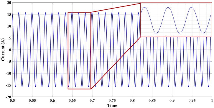
In Figure 4, the grid-injected current for the inverter output without Kalman filter is plotted and Figure 5 shows the FFT analysis for the same. The Kalman filter-based mitigation is applied and the grid current is obtained in Figures 6 and 7 shows the FFT analysis for the grid-injected current for the inverter. The THD without Kalman filter-based technique was 6.42% which is improved to 2.49% with the proposed Kalman-based technique.
Figure 4.
Grid-injected current without Kalman filter.
Figure 5.
FFT analysis of the grid-injected current without Kalman filter.
Figure 6.
Grid-injected current with Kalman filter.
Figure 7.
FFT analysis of the grid-injected current with Kalman filter.
The comparison of the proposed Kalman filter-based techniques with other filters is tabulated in Table 3.
To reduce the harmonic distortion of the inverter, a Kalman filter-based harmonic mitigation strategy is used. The grid is not healthy because harmonic distortion is created by the presence of power converter components. Due to the reduction of harmonics, the output current power quality has been significantly improved. By generating a harmonic voltage with a similar amplitude but opposite phase, the filter compensates for voltage harmonics, resulting in sinusoidal voltage and current waveforms. In compliance with IEEE 519-2022 standards, the THD was 6.32% prior to the suggested Kalman filter and decreased to 2.49% following the Kalman filter-based mitigation measures. Increasing the number of renewable energy sources connected to the grid will result in power converters being used more frequently to convert DC power to AC power, resulting in harmonic injected current. Since these harmonics are detrimental to the system’s functionality, suitable power converters and control schemes must be developed for renewable energy that is connected to the grid.
1.Rodriguez J, Lai J-S, Peng FZ. Multilevel inverters: A survey of topologies, controls, and applications. IEEE Transactions on Industrial Electronics. 2002;49(4):724-738. DOI: 10.1109/TIE.2002.801052
2.Bughneda A, Salem M, Richelli A, Ishak D, Alatai S. Review of multilevel inverters for PV energy system applications. Energies. 2021;14(6):1585. DOI: 10.3390/EN14061585
3.Lei Y et al. A 2-kW single-phase seven-level flying capacitor multilevel inverter with an active energy buffer. IEEE Transactions on Power Electronics. 2017;32(11):8570-8581. DOI: 10.1109/TPEL.2017.2650140
4.Nirmal Mukundan CM et al. A new multilevel inverter based grid connected reliable solar power transfer unit with power quality enhancement. IEEE Transactions on Industry Applications. 2023;59(2):1887-1900. DOI: 10.1109/TIA.2022.3218523
5.Pourfarrokh S, Adabi J, Zare F. A novel multilevel inverter with self-balancing capability of capacitors voltage; structure, modulation and operation. IEEE Journal of Emerging and Selected Topics in Power Electronics. 2023;11(2):1854-1864. DOI: 10.1109/JESTPE.2022.3222344
6.Roy S, Debnath A, Tariq M, Behnamfar M, Sarwat A. Characterizing current THD’s dependency on solar irradiance and supraharmonics profiling for a grid-tied photovoltaic power plant. Sustainability. 2023;15(2):1214. DOI: 10.3390/SU15021214
7.Luo S, Wu W, Koutroulis E, Chung HSH, Blaabjerg F. A new Kalman-filter-based harmonic current suppression method for the virtual oscillator controlled grid-tied inverter. IEEE Journal on Emerging and Selected Topics in Circuits and Systems. 2022;12(1):251-259. DOI: 10.1109/JETCAS.2022.3141106
8.Chen B, Wu W, Gao N, Yao Z, Chung H, Blaabjerg F. Kalman-filter-estimation based sliding mode control of three-phase LCL-filtered grid-tied inverter using only grid-injected current sensors. In: IEEE 9th International Power Electronics and Motion Control Conference (IPEMC2020- ECCE Asia). 2020. pp. 2368-2373. DOI: 10.1109/IPEMC-ECCEAsia48364.2020.9367829
9.Ravikumar A, Mohan N, Soman KP. Performance enhancement of a series active power filter using Kalman filter based neural network control strategy. In: 2018 International Conference on Advances in Computing, Communications and Informatics (ICACCI). 2018. pp. 1702-1706. DOI: 10.1109/ ICACCI.2018.8554889
10.Dewangan P, Dewangan PK, Nagdeve UT. A review of single-phase grid-connected inverters for photovoltaic generation system. International Journal of Research. 2014;1(9):521-525. DOI: 10.1109/TIA.2005.853371
11.Akbari A, Poloei F, Bakhshai A. A brief review on state-of-the-art grid-connected inverters for photovoltaic applications. In: IEEE International Symposium on Industrial Electronics. 2019. pp. 1023-1028. DOI: 10.1109/ ISIE.2019.8781166
12.Nabae A, Takahashi I, Akagi H. A new neutral-point-clamped PWM inverter. IEEE Transactions on Industry Applications. 1981;IA-17(5):518-523. DOI: 10.1109/TIA.1981.4503992
13.Peng FZ. Z-source inverter. In: IEEE Trans- actions on Industry Applications. Vol. 39, no. 2. 2003. pp. 504-510. DOI: 10.1109/TIA.2003.808920
14.Gupta KK, Ranjan A, Bhatnagar P, Sahu LK, Jain S. Multilevel inverter topologies with reduced device count: A review. IEEE Transactions on Power Electronics. 2016;31(1):135-151. DOI: 10.1109/TPEL.2015.2405012
15.Iqbal H, Tariq M, Sarfraz M, Anees MA, Alhosaini W, Sarwar A. Model predictive control of packed U-cell inverter for microgrid applications. Energy Reports. 2022;8:813-830. DOI: 10.1016/j.egyr.2022.05.188
16.Pakdel M, Jalilzadeh S. A new family of multilevel grid connected inverters based on packed U cell topology. Scientific Reports. 2017;7(1):12396. DOI: 10.1038/s41598-017-12806-5
Written By
Hasan Iqbal, Asadullah Khalid, Hugo Riggs and Arif Sarwat
Submitted: 12 February 2024Reviewed: 01 March 2024Published: 03 May 2024