
Abstract
Optical wireless communication (OWC) is a strong candidate in the sixth generation (6G) of wireless communications as it can support data transmission at high communication speeds, low power consumption, high security, and high reliability. Near-infrared lasers, specifically vertical cavity surface emitting lasers (VCSELs), exhibit larger modulation bandwidth compared to light-emitting diodes (LEDs), and can provide aggregate data rates ranging up to Terabit per second (Tbps). This chapter proposes innovative optical transmitter and receiver designs for indoor laser-based wireless communications, aiming to provide seamless coverage in high-speed multi-user scenarios. The proposed optical transmitter is based on a 5 × 5 VCSEL array where each VCSEL can provide 10 Gigabit per second (Gbps) in a uniform coverage area of 20 cm x 20 cm, achieving a total of 250 Gbps in an area of 1
Keywords
- 5G wireless networks
- 6G wireless networks
- optical wireless communications
- LEDs
- infrared lasers
- networking
1. Introduction
The number of wireless communication devices is increasing rapidly, with the goal of providing easy internet access everywhere, unobstructed broadband services, reliable monitoring of users’ health conditions and environmental conditions, etc. In the next generation of wireless networks, aggregate data rate in a range of Tbps must be achieved to support the unprecedented growth of data traffic. Optical wireless communication (OWC) can offload heavy traffic loads from current radio frequency (RF) wireless networks as it operates over the expansive and license-free optical spectrum.
Light fidelity (LiFi) is a version of OWC technology that uses light-emitting diodes (LEDs) as optical transmitters to deliver high-speed data communication in a similar manner to WiFi. Basically, LiFi is a bidirectional and fully networked wireless communication usually deployed in indoor environments to provide both illumination and communication [1, 2]. Several types of LEDs preferred for use in this context are listed as follows:
Phosphor converted LED (PC-LED): A single blue Indium Gallium Nitride (InGaN) LED chip is used to pump a Yttrium Aluminum Garnet (YAG) phosphor coating. The phosphor converts part of the blue light to green, yellow and red portions of the spectrum while the other part of the blue light is leaked out, and the mixture of which produces white light [3].Multi-chip LED: Such LEDs generally combine three or more sources emitting different colors, typically red, yellow, green and blue (RYGB). Compared to the PC-LED, the multi-chip LEDs offer higher aggregate data rates with the utilization of wavelength division multiplexing (WDM).Micro-LED ( μ -LED): This is an advanced form of LEDs that is able to achieve modulation bandwidths in a range of hundreds of MHz [4], and therefore provides high data rates per transceiver chain. Theμ -LEDs have a small sizeOrganic LED (OLED): It is a popular technology for flat panel displays, in which the light is generated from organic thin films sandwiched between an anode and a metal cathode. The typical modulation bandwidth of OLEDs is around hundreds of kHz [5].Quantum Dot LED (QLED): This type of LED uses quantum dots as light-emitting material. With different materials and processes, QLED has shown very impressive results so far for bright display panels and can offer modulation bandwidth up to MHz [6, 7]. However, this constrained bandwidth renders them less suitable as optical transmitters for multi-Gbit/s communication.
On the other hand, laser diodes, especially vertical cavity surface emitting lasers (VCSELs), provide larger modulation bandwidth compared to LEDs. VCSELs also exhibit other outstanding features such as high power conversion efficiency, low cost, long lifetime, and ease of manufacture, which make them the most promising candidates to fulfill the exceptional demands of the next generations of wireless networks. Near-infrared (NIR) VCSELs have shown the potential to support data transmission at Tbps communication speed [8] with low complexity modulation and detection techniques compared to LED-based OWC, which requires advanced signal processing techniques to achieve Gbps aggregate data rates. However, two of the major challenges in laser diodes OWC are expanding the coverage area of the laser to support mobility considering the narrow beams, and ensuring that the transmit power can meet the eye safety regulations [9].
The aim of this chapter is to derive new components, transmitters and receivers, and define crucial networking techniques to unlock the full potential of OWC in 6G networks. We First propose an array of VCSELs as an access point that ensures uniform coverage up to a few square metres in order to provide seamless data transmission service in the real-world deployment of OWC. Then, two trade-offs in designing optical receivers are highlighted to enhance the field of view (FoV) and data rate. Finally, the chapter focuses on the limitations of laser-based OWC from the networking perspective and provides solutions to bring its implementation to reality.
2. 6G optical transmitters and receivers
2.1 Transmitters
Both LEDs and laser diodes can be used as the sources for OWC links. LEDs are the most common sources because they are widely deployed in indoor illumination. However, they suffer from relatively limited bandwidth, which restricts the achievable rates [1]. On the other hand, laser diodes (LDs) can provide much higher (
Despite these advantages, VCSELs also exhibit certain drawbacks. Most evidently, commercially available high-bandwidth VCSELs are mainly multi-mode devices and exhibit a doughnut-shaped beam profile. Without proper optics, this particular type of beam profile gives non-uniform power and SNR distributions, which is problematic for OWC applications with wide coverage areas. Moreover, doughnut-shaped beam spots, when intended for full coverage in the far-field, create overlaps in the illuminated area, causing interferences between adjacent atto-cells.
To overcome these issues, a novel transmitter design is proposed which can be used with both multi-mode and single-mode VCSELs. Moreover, unlike many laser-based OWC designs in the literature which focus on single-user, high-speed point-to-point link with relatively long transmission range [10, 11, 12], the proposed transmitter design aims to provide a wide-area coverage for multiple users, offering a high tolerance for alignment and user mobility. Moreover, as each channel of the proposed transmitter generates a square atto-cell of 20 cm × 20 cm with high intensity uniformity (90%, verified through simulations and experiments [13]) and adjustable cell-to-cell distance, the inter-cell interference is minimized.
The schematic of the transmitter design is shown in Figure 1. In the proposed design, a micro lens array (MLA1) with the same pitch as the VCSEL array is used to collimate the transmitted beam. A wide beam-to-beam separation is achieved with the help of a pair of Plano-concave lenses (PCV1 & PCV2). After beam separation, each beam is coupled into an individual homogenizer formed by plano-convex lens (PCX), MLA2 and MLA3. The final image at 3 m is obtained by passing the output beams from the homogenizer through a PCX2, generating 20 cm × 20 cm coverage for each channel.
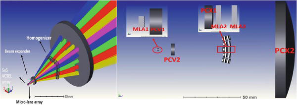
Figure 1.
System diagram (left) and lens arrangement (right) of the proposed VCSEL array [
The designed transmitter can serve 25 users with
2.2 Receivers
The design of high-speed optical receivers is a crucial aspect in the development of indoor laser-based communication for 6G. The general structure of an optical wireless receiver must consist of optics to collect sufficient power, a detector, and the associated driving circuit, as illustrated in Figure 2. Developing high-speed, compact, and wide field-of-view (FOV) receivers, which can operate reliably in a mobile environment, presents inherent challenges due to two recognized trade-offs. The first trade-off is the area-bandwidth trade-off of the photodetector (PD). To support high data rates, small PDs with higher bandwidths are required. It is important to highlight that using a small-area PD, which has a high bandwidth, may not be preferable since it introduces less received power. One solution to address the area-bandwidth trade-off is to improve the receiver sensitivity by using avalanche photodiodes (APDs) or single-photon avalanche diodes (SPADs). However, the performance of these detectors is limited by their noise signal-dependency and limited dynamic ranges. Another effective and frequently employed approach to tackle this issue is employing optics in front of the PD to enhance the received power. However, this can lead to limitations on the receiver FOV as a result of the law of conservation of etendue, bringing the second trade-off known as the gain-FOV trade-off. Note that while narrow receiver FOVs are preferred in outdoor FSO systems with complex pointing and tracking subsystems capable of maintaining line-of-sight connectivity, indoor laser-based wireless systems typically require larger receiver FOVs to facilitate mobility support.

Figure 2.
General structure of optical wireless receivers.
The gain-FOV trade-off is caused by the use of optics, indicating that the optical gain is achieved at the expense of a reduced FOV. Depending on the types of optics, there are two broad categories of optical receivers: imaging receivers and non-imaging receivers. Imaging receivers use a lens or other optical element to focus incoming light onto a detector. Non-imaging receivers, on the other hand, rely on other mechanisms such as waveguides or fiber optic cables, to deliver light to the detector. Imaging receivers are typically more popular due to the availability of varieties of low-cost lenses with different sizes as well as lenslet arrays. Imaging receivers benefit from smaller heights, however, they have a smaller FOV compared to non-imaging receivers.
The combined effects of the aforementioned trade-offs lead to a new trade-off between the achievable data rate and receiver FOV, which is called rate-FOV trade-off [14]. This is due to the fact that attaining a higher data rate necessitates a broader bandwidth and an increased received power, both of which reduce the FOV. Several studies have investigated the enhancement of FOV of high-speed optical receivers. One approach is the utilization of an angle diversity receiver (ADR) which comprises several narrow-FOV receiver elements oriented in different directions [15], using non-imaging optics [16, 17, 18] or imaging optics [19], as illustrated in Figure 2. A wide-FOV receiver that incorporates fused fiber-optic tapers is proposed in [20], integrating hundreds of thousands of tapered optical fibers. The reported specifications include an overall FOV of
We recently introduced two innovative wide-FOV receiver designs tailored for high-speed OWC systems, as presented in [14, 18]. In [14], a multi-element imaging receiver design based on an array of arrays is proposed, as depicted in Figure 2. In the proposed structure, every receiver element comprises an inner PD array and a lens that focuses the light onto the inner array. Multiple receiver elements are combined to create the outer array, enhancing the overall optical gain performance. To maintain the receiver bandwidth, each PD is followed by a transimpedance amplifier (TIA) and various combining techniques can be employed to process the output signals of each PD. The PD side length and the distance between the lens and the array can be optimized subject to specific design constraints. Numerical findings indicate that for a minimum required half-angle FOV of
3. Networking architecture for laser-based LiFi
In this section, advanced techniques relevant to the architecture of indoor laser-based wireless communication networks are discussed, addressing issues such as cell formation, interference management, resource allocation, and backhauling.
3.1 Cell formation
Using lasers for data transmission results in various features including high data rates, security and energy efficiency. However, the coverage area of the laser is very confined and can be limited to a few centimeters. In this context, laser-based OWC networks can be designed based on the deployment of a large number of APs. Each AP is an array of VCSELs illuminating a confined area referred to as attocell, and a dense laser-based OWC network guarantees seamless transition for mobile users. Considering this cellular network design, inter-cell interference (ICI) among users belonging to different cells must be controlled. In [23, 24], frequency reuse (FR) was proposed to manage the interference among a number of optical cells. Essentially, a set of frequencies is used among adjacent cells, and then, each frequency can be reused by an optical cell located at a farther distance. Therefore, the interference between two optical cells using the same frequency band can be treated as noise. Furthermore, fractional frequency reuse (FFR) was studied in [25, 26], where the coverage area of an optical cell is divided into three regions, applying different frequency reuse factors in each region. Therefore, the users located at the edge do not interfere with each other, while the users located at the center receive minimum interference. In laser-based networks with very small attocells, users with high mobility may be subject to handover every few centimeters, which then results in the need for resilient handover schemes to ensure continuous service. Given this point, a network-centric (NC) approach was proposed in [24, 27, 28] as shown in Figure 3, to overcome the limitations mentioned above in terms of the small coverage area of the optical AP and the enhancement of SNR. In the NC design, the whole receiving plane is divided into multiple static cells, each cell with multiple APs that jointly serve multiple users. It is shown that the NC design can minimize the ICI, and therefore, the performance of the optical network can be enhanced considerably compared with cellular networks deploying FR or FFR-based independent transmission per cell. However, the drawbacks of the NC design must be taken into consideration such as the static shape of the NC cells over time as they are formed regardless of the distribution of users, and the NC design might lead to an imbalance in the load among the formed cells where one of the cells might end up serving a high number of users compared to other cells. In contrast, a network topology given by the user centric (UC) perspective was designed in [27, 28, 29, 30] to avoid the ICI among multiple optical cells and achieve high data rates. The UC cells in Figure 3 are characterized by their elastic shapes where they are formed as a function of the distribution of users. Therefore, the UC design is updated over time in response to any changes in the network resulting from the mobility of users. Compared to the NC design, the UC approach involves high complexity and additional signaling. However, it is worth implementing since it enhances the performance of the laser-based OWC network significantly in terms of SNR and data rate.

Figure 3.
Cell formation example. (a) Independent transmission per each cell, (b) NC approach, (c) UC approach.
Figure 4 shows the performances of various optical network formations in an indoor environment designed using MATLAB with dimensions 8 meters × 8 meters × 3 meters (Width × Length × Height), where 4 × 4 laser-based APs are deployed on the ceiling to ensure uniform coverage for 20 users distributed on the communication floor. Other parameters such as bandwidth is 1.5 GHz, optical transmit power is calculated as in [13] to ensure eye safety, laser wavelength is 1550 nm, and laser noise is −155 dB/Hz. Considering orthogonal transmission among the users of each optical cell, the UC formation is superior compared to non-unity FR, FFR and NC formations where more than 60% of the users achieve spectral efficiency beyond 15 [bits/s/Hz]. It is worth mentioning that the optimum UC topology has high complexity that increases with the density of the network, while the NC formation is deployed by simply dividing the number of APs into multiple NC cells where each NC cell serves users within its coverage area. However, NC does not eliminate ICI completely, and the complexity of the UC formation can be relaxed by implementing sub optimal solutions such as the well known
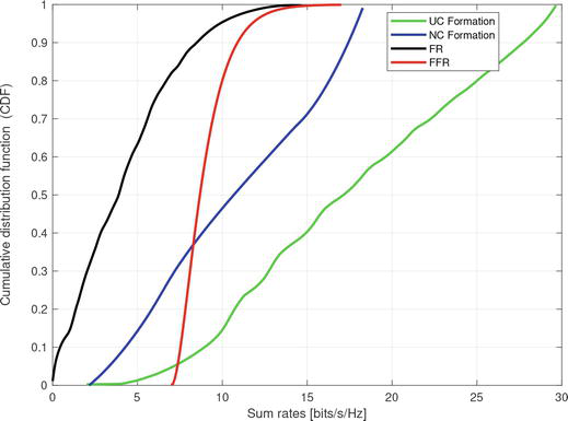
Figure 4.
The CDF curves of the sum rate.
3.2 Interference management
In laser-based OWC networks, serving a high number of users requires efficient interference management schemes to align data streams transmitted to users with a minimum error. Orthogonal transmission schemes such as time division multiple access (TDMA) [31], space-division multiple access (SDMA) [32] and orthogonal frequency division multiple access (OFDMA) [33] were implemented to manage the interference among multiple users through transmitting data streams in an orthogonal fashion giving users the ability to decode their information independently in the absence of interference in their allocated time, frequency or space channels. Despite the low complexity of these schemes, they limit the capacity of laser-based OWC networks due to the fact that users cannot be served over the same frequency or time slots. Another orthogonal approach that is particularly suited for the OWC technology is wavelength division multiplexing (WDM), which was used in [34, 35] by employing RGBY LEDs for data transmission. The WDM can support a number of colors to serve multiple users by allocating a different color to each user. In this context, optical filters must be used on the receiver side to differentiate various wavelengths. However, having many different colors and a broad emission spectrum can result in crosstalk among colors where optical filters cannot distinguish the wavelengths [36]. This issue might not affect the performance of multi-user laser-based OWC networks to the same degree due to the fact that lasers have a narrower emission spectrum. The aim of this subsection is to highlight promising techniques for interference management in laser-based OWC networks.
3.2.1 Precoding schemes
Transmission precoding (TPC) schemes such as minimizing the mean square error (MMSE) [37], zero-forcing (ZF) or interference alignment (IA) [38] derived originally for RF networks were implemented for OWC networks. It is shown that these TPC schemes can potentially increase the capacity of OWC networks compared to orthogonal transmission schemes. However, they are more suitable for RF networks due to the distinct nature of transmitted RF signals compared to optical signals. For example, TPC schemes might not achieve their full performance of interference management in laser-based OWC networks due to the non-negativity constraint of the optical signal. Given that, TPC schemes must be modified through applying a DC bias current that can eliminate the negative part of the transmitted signal. Therefore, MMSE and ZF schemes were adjusted in [37, 38], respectively, considering the constraints of the optical channel. Furthermore, in [39], a power allocation optimisation problem was formulated in order to maximize the data rate of a TPC-based OWC system constrained by the illumination function. However, encoded information may experience distortion resulting from adding the DC bias current. Moreover, TPC schemes require channel state information (CSI) at the transmitters to maximize the multiplexing gain of the network. Note that providing accurate CSI is not straightforward, and its cost increases considerably with the density of the network. As mentioned, Laser-based OWC networks are expected to be very dense networks, and therefore, the cost and imperfection of CSI must be taken into consideration in such cellular networks. For instance, having a frequency division duplex (FDD) system1, a fraction of the network resources is dedicated for transmitting estimation pilots. Also, resources must be assigned for feeding back information to the transmitters through the uplink transmission. The estimation pilots are transmitted in an orthogonal fashion over time slots given by the number of transmitters. Therefore, the implementation of TPC schemes in laser-based OWC networks may result in inefficient use of resources.
3.2.2 Non-orthogonal multiple access
A transmission scheme referred to as non-orthogonal multiple access (NOMA) was proposed in [40] to enhance the spectrum efficiency of RF networks. In NOMA, users are grouped based on the channel difference in order to serve them over the same frequency or time slot by allocating different power levels to each data streams. It is shown that NOMA can enhance the capacity of RF systems compared to orthogonal transmission schemes in which exclusive frequency or time resources are assigned to each user. NOMA can be implemented in OWC systems to offer enhanced user experience. However, the fundamental differences between RF and optical systems in terms of the coverage area, number of APs and nature of the transmitted signal result in new challenges. In [41], NOMA was proposed for interference management in an optical system where the sum rate was maximized by tuning the semi-angle of the optical AP and the field of view (FoV) of the receptor. In [42], NOMA operating under illumination constraints shows superior performance compared to other orthogonal transmission schemes. In [43], the performance of NOMA was evaluated in an optical system serving multiple users where each user has a target requirement in terms of QoS.
In a laser-based OWC network, NOMA can be implemented by first sorting the users in ascending order based on their channel gains, and then, forming multiple pairs of strong and weak users using a clustering algorithm. Note that, the interference among the groups must be managed, while NOMA is considered for transmission within each group. The users in NOMA receive power control coefficients based on their channel gains. These power coefficients can be determined through optimization problems that aim to maximize the sum rate under fairness between the weak and strong users. In general, NOMA allocates less power to the strong users located close to the transmitters, while more power is allocated to the users with poor channel gains. The strong user must perform successive interference cancelation (SIC) to decode the information with high power first and subtract it from the received signal. This process is followed by the strong user iteratively until it decodes the useful information. On the other hand, the weak user can decode its information from the received signal while managing other information as noise. In extreme scenarios, the strong user can foreword the desired information and server the weak user through other links such as RF networks deployed as complementary networks, i.e., hybrid optical/RF networks.
3.2.3 Blind multiple access
Blind interference alignment (BIA) was proposed for RF networks in [44] in order to align the interference among users without the need for CSI at the transmitters. BIA exploits the channel correlation among users, where each user is equipped with a reconfigurable antenna. In [45], the performance of BIA was compared to ZF taking into consideration the cost of providing CSI at the transmitters. It is shown that BIA is more suitable than ZF in terms of SNR. For OWC systems, a new optical detector referred to as a reconfigurable detector was derived in [46] to implement BIA and avoid the need for CSI at the optical transmitters. The reconfigurable receiver is a set of PDs connected to a single signal processing chain through a selector. Therefore, it has the ability to provide a set of independent channel responses, which are essential for implementing BIA. Interestingly, BIA is characterized by its non-negative precoding matrix given by {0
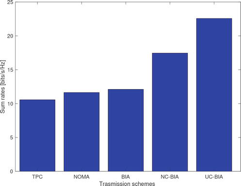
Figure 5.
The sum rates of different interference management schemes.
3.3 Resource allocation
Given the remarkable developments and rapid evolution of communication networks and computing architectures, resource allocation continues to be a non-trivial matter, due to the fact that users are always demanding better QoS, which is driven by the increasing demand for services that are computationally intensive and/or bandwidth hungry. The developed resource allocation framework must be able to cope with various new emerging architectures such as wired/wireless mesh networks, multi-protocol networks, cognitive networks, cloud/fog computing systems, etc. Over the recent years, various tools and techniques have been utilized. These tools include optimization theory: centralized solutions such as mixed integer linear programming (MILP) and distributed ones such as game theory, and auction theory, to name a few. Therefore, given the complex nature of communication systems, especially those that comprise of multiple users and heterogeneous set of resources, it becomes imperative to design advanced resource allocation methodologies in order to ensure the optimal performance of such systems whilst users’ QoS is guaranteed [48, 49, 50, 51]. In this subsection, we focus on an end-to-end cloud/fog infrastructure as shown in Figure 6, which consists of multiple OW mobile user devices clustered inside a room forming a mobile fog unit (MobFog). It is assumed that each mobile device can establish a link with one or more light units and is assigned to only one of the available channel wavelengths. All of the APs are connected over a passive optical network (PON) and each AP is connected to an optical network unit (ONU). In return, the OLT aggregates the traffic from all of the ONUs towards other layers in the network. A low-end server, which acts as a fog node (RoomFog) is connected to the OLT device in the same room using a dedicated ONU. Moreover, there are three more fog data centers that are located in the building (BuildingFog), campus (CampFog) and the metro layer (MetroFog). These fog nodes are integrated with the centralized cloud data center (CCloud) over the optical networking infrastructure so that highly demanding requests that cannot be processed by mobile fog or fog nodes, can be processed at the cloud. When a task is allocated to the MobFog for processing, the OLT device sends this task to the participant’s mobile devices that are clustered as a fog node via the OWC communication. Then once processing is completed, the output is sent back to the OLT. In other cases where a task has to be assigned to the RoomFog, BuidlingFog, or CampFog nodes, the local Ethernet LAN is used to establish the communication with the required location. However, for processing at the MetroFog or CCloud, demands must be sent over the optical infrastructure to either location.
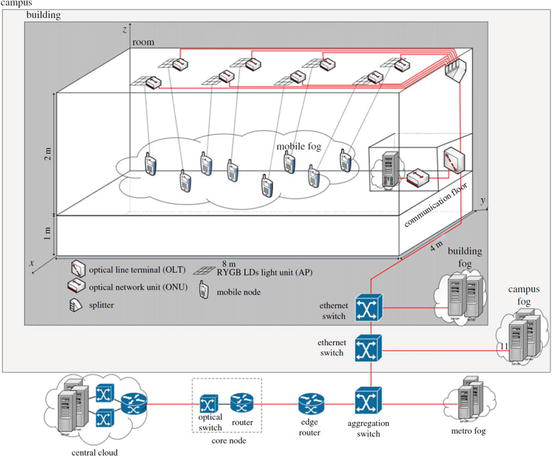
Figure 6.
A cloud/Fog Architecture with OWC Front-End [
3.3.1 Cloud/fog network with an OWC front-end
In OWC systems, multiplexing and multiple access techniques are imperative in order to support multiple users. Therefore, to avoid signal quality degradation introduced in a multi-user setting, efficient utilization of resources can mitigate such issues. As for computing, motivated by the goal of reducing latency and power consumption, recently, researchers have focused on emerging distributed architectures with the aim of offloading the processing workloads from the centralized data center. In this direction, distributed “mini” data centers have emerged as the new generation of cloud computing whereby processing demands are “distributed” among fog nodes that are closer to end-user devices. This distributed processing approach results in faster response time in addition to the reduced networking burden. It is important to note that an efficient networking fabric is pivotal for distributed processing. In this regard, OWC systems can offer data rates in a range of Gbps and beyond, thus these mediums can be viewed as promising for supporting the front-end of distributed fog networks in indoor environments [52, 53].
3.3.2 Distributed processing and fog computing
Fog computing is a well-known distributed processing solution that was first coined by Cisco in 2012, and it was aimed at extending the cloud functionalities from the core of the network to the edge of the network, hence closer to the end-user devices [54]. Oftentimes, decision-making can be made better and quicker if the collected data is processed at the edge of the network in close proximity to the source nodes. Currently, fog computing is still in its infancy and a standardized architecture has yet to be agreed. Thus, alternative fog architectures are increasingly being studied in the research community, especially the interplay between the edge devices (fog) and the core (cloud), since fog is regarded as a powerful complement to the cloud. Also, a proper resource allocation scheme is crucial in the fog, as application services can be placed in a highly energy inefficient server or even further from the source node which results in higher communication latency. It is expected that through cooperation between fogs and the centralized cloud, a more efficient and greener computing platform can be achieved [55]. Fog nodes are normally formed by building distributed mini data centers in the network, using a smaller scale of low-end servers [56]. However, due to the unprecedented number of highly intelligent embedded devices at the edge such as IoT devices, which are mostly underutilized has lead to a new definition of fog computing. These IoT devices can collectively provide huge amounts of computational resources when they are clustered together to form a fog mini data center [57].
3.3.3 Optimum resource allocation in OWC networks
Two stages of OWC resource allocation is considered here. In the first stage, the resource allocation problem is modeled in the OWC environment, where the mobile devices are assigned optimally to wavelengths and subsequently to APs. The WDMA or any other advanced technique can be used to support the multiple access of users. It is assumed that the optical line terminal (OLT) inside the room acts as the controller and has global knowledge on users’ locations as well as their channel information. The developed mixed integer linear programming (MILP) model in [48] can be used to assign APs and wavelengths to users (end-devices) so that the sum of user SINRs or data rates is maximized. In the second stage, the output of the optimization model in the first stage can be used to jointly optimize the assignment of users to APs and wavelengths and the cloud/fog that involves the optimal placement of processing tasks so that the total power consumption is minimized.
3.4 Backhaul links
Backhaul is an essential component of wireless cellular networks, granting base stations access to the core network. With the continuous trends of cell densification and data rate aggregation and the emergence of real-time bandwidth-hungry services in 5G networks and beyond, devising a cost-effective backhaul solution is a major challenge. Besides, for future 6G wireless systems, indoor Tb/s wireless access systems are envisioned as a means to offload busy data traffics from massively deployed broadband WiFi and mobile cellular networks. This requires an efficient backbone network that can support aggregate data rates of multi-Tb/s from laser-based optical wireless links.
A natural option for realizing high-capacity backhaul links is the distribution of optical fiber cables in the indoor environment where the Tb/s access network is deployed. In a star topology, every AP is individually equipped with an optical fiber link that connects it to the fiber distribution hub through which it is routed to the Internet. However, this is feasible if the expenditure incurred due to redesigning the wiring infrastructure is justifiable. 80% of Internet traffic was reported to initiate and terminate indoors. Thus, it improves such a fiber distributions network if its connections are in the form of a data network (i.e. replacing the star topology with a richer network). Such a network can then meet these indoor demands, which can be in the form of user-to-user and IoT-to-IoT communication in addition to user-to-Internet and vice-versa traffic. Figure 7 illustrates how such a network can connect a number of rooms in a building. Improving the connections between APs within a room, floor or a whole building and the final gateway is beneficial for users and service providers as it can reduce both data transmission delay and networking power consumption.
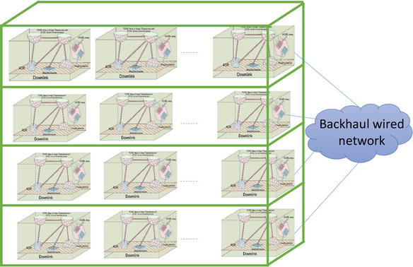
Figure 7.
Wired backhaul network to connect APs in different rooms within a building.
PONs are key technologies for energy efficient solutions. We will also show that among the different options, some solutions are more adaptable than others. Different solutions can be listed as:
PON-based on a TDMA technology and adopting a tree topology: The network is fully passive and minimizes the number of fibers deployed in the field. The drawback is a physical bit rate at the subscriber side that follows the aggregated bit rate. Since the power consumption is sensitive at the periphery of the network, this solution operating at ultra-high bit rates could be limited.Passive Optical networks exploiting WDMA technologies: Each subscriber has a physical interface corresponding to its guaranteed bandwidth. The aggregation is made with optical multiplexers to transport the data of several subscriber onto a same fiber. This solution can require tunable lasers to adapt the wavelength, in particular, if the transport fiber is shared with another PON system. This solution could be adapted for low power consumption.Fiber to the building solutions: The transport data is based on TDM techniques. The connections of the trunk may be terminated in the basement of a building or in the street cabinet. The objective here is to disaggregate the bit rate, to offer a physical bit rate at the subscriber side as close as possible to the guaranteed bandwidth. For example, interleaving techniques can be implemented as well as disaggregation techniques.Passive optical LANs (POL): POLs offer the possibility to distribute the couplers to adapt the connectivity to a room of a space. The main drawback is that the aggregated bit rate is imposed on the subscribed side.Optical ring networks: They are relevant when there is a risk of fiber cuts. Typically, this technology is better positioned than PONs for outdoor interconnection. It is also a good solution to offer machine-to-machine (M2M) communication (for example in factories). With proper management of the physical layer, it is easier to increase the number of interconnection points, when compared to a PON.
The physical ring topology guarantees the M2M service through the adoption of broadcast and select mechanisms. An optical ring based on optical add/drop multiplexers (OADM) is guaranteed to have a high level of reliability (if a node is in failure the optical ring is not impacted and the traffic is not interrupted). Finally, the ring topology offers natural protection schemes by doubling the ring and by exploiting the bidirectionality. For time sensitive networks, it is proposed to combine OADMs operating in WDM regime, acceleration of the bit rate (from
Insertion delay:
One delay to form the slot:
One delay to insert the slot in the ring: delay
total:
Transit delay:
0 delay, since there is no in line processing for header with the B&S mechanism
Drop delay:
One delay to extract the control channel and synchronize the control channel with the data stream: delay
The total end-to-end latency (without the propagation delay of the ring) is
The implementation of multiple topologies can ensure higher sustainability and availability of the network. The use of one topology (tree, bus or ring) cannot be enough to satisfy the exigence of some use cases. It is then mandatory to envisage multiple topologies. For example in factories where the communication of machines is important to control the production process step by step, optical ring networks are required. By adopting broadcast and select techniques it is then possible to offer unicast or multicast connections to enable this machine-to-machine service. If we are in the case of a multiclient factory, then a PON can be important to interconnect the different aggregation points of the ring networks to the PON. This is a typical case where ultra-high bit rate PON will be required. For some other use case like the deployment of OWC AP in a hospital it could be more adapted to deploy a POL per floor and interconnect different POL using a ring network.
As a cost effective solution, the IEEE 802.3bt PoE++ becomes the standard for connected homes and buildings. Proposing a network topology where LiFi access points (APs) connected using a PoE++ Gigabit Ethernet reduces the cost of integration, deployment and maintenance. Keeping the same passive optical LAN topology in Figure 6, a new networking option, which consists of an interconnecting optical network unit (ONU) with a PoE++ switch equipped with the small form-factor pluggable (SFP) ports, is suggested by Crantec. This interconnection will then create a 802.3bt PoE++ Gigabit Ethernet LAN backbone to deploy a LiFi wireless network as illustrated in Figure 8. In a distributed architecture, LiFi APs can be connected to the 802.3bt PoE++ network using the industrial micro switch. If a VCSEL arrays LiFi AP is then equipped with a PoE network connectivity, it can be easy and at a low cost to connect it to a Gigabit Ethernet switch as shown in the Figure 9.
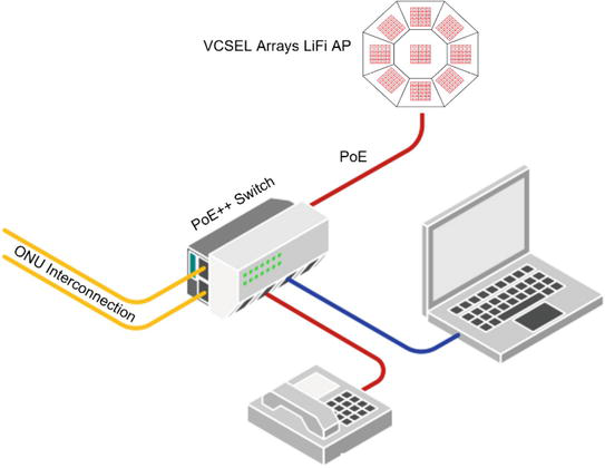
Figure 8.
Indoor PoE++ LiFi wireless LAN network connecting a VCSEL arrays LiFi AP. The LiFi AP shown in this figure is based on an array of arrays of VCSELs referred to as the double-tier AP architecture [
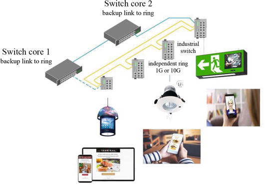
Figure 9.
Indoor PoE++ LiFi wireless LAN network mobile applications & services. The LiFi AP.
For such a network shown in Figure 7, this chapter proposes a WDM-PON network [59], which uses passive Arrayed Waveguide Grating Routers (AWGRs) and an OLT port to realize all-to-all non-blocking connections using a number of predefined wavelengths. An AP can then tune the wavelength of a transceiver to communicate with another AP and directly serve user-to- user traffic. The performance and energy consumption of this proposal was compared to a widely used data network which is a Spine-leaf network design. This network contains two layers of fully connected electronic switches. The comparison was performed under optimized routing for user to user traffic with the objective of minimizing the power consumption or the delay, and WDM-PON networks show superiority over Spine-leaf data networks.
An alternative approach is the use of laser-based optical wireless links to interconnect APs with the core network. It is shown that ultra-high-speed transmission rates of more than 1 Tb/s can be achieved based on VCSEL arrays and multiple-input multiple-output (MIMO) system configurations [60, 61]. Note that, crosstalk in the MIMO channel is one of the challenges in such configurations where the beam spots of VCSELs at the receiver end must be confined. As a consequence, a practical limitation of line-of-sight (LOS) MIMO optical wireless link design with laser beams of very low divergence angles is that it requires precise alignment. Therefore, in realistic scenarios, the system performance is prone to any kind of misalignment arising from installation errors or transceiver vibrations.
4. Conclusions
The chapter provides a thorough study on the use of OWC in 6G wireless networks. We first design new optical transmitters and receivers to support the extreme demands of current and future Internet-based applications. Multiple VCSEL arrays deployed in an indoor environment can ensure uniform coverage in multi-user scenarios and provide aggregate data rate transmission in a range of Tbps. On the receiver end, we introduce an array of PD arrays to enhance the FOV, gain and bandwidth, and to support ultra-high-speed optical links. Finally, various challenges and potential solutions from the networking perspective are discussed to help build an end-to-end OWC infrastructure in real-world deployment of 6G wireless networks.
Acknowledgments
The authors acknowledge financial support from the EPSRC under program grant EP/S016570/1 ‘Terabit Bidirectional Multi-User Optical Wireless System (TOWS) for 6G LiFi’.
References
- 1.
Haas H, Yin L, Wang Y, Chen C. What is LiFi? Journal of Lightwave Technology. 2016; 34 (6):1533-1544 - 2.
Soltani MD, Xiping W, Safari M, Haas H. Bidirectional user throughput maximization based on feedback reduction in LiFi networks. IEEE Transactions on Communications. 2018; 66 (7):3172-3186 - 3.
Steigerwald DA, Bhat JC, Collins D, Fletcher RM, Holcomb MO, Ludowise MJ, et al. Illumination with solid state lighting technology. IEEE Journal of Selected Topics in Quantum Electronics. 2002; 8 (2):310-320 - 4.
McKendry JJD, Massoubre D, Zhang S, Rae BR, Green RP, Erdan G, et al. Visible-light communications using a cmos-controlled micro-light-emitting-diode array. Journal of Lightwave Technology. 2012; 30 (1):61-67 - 5.
Karunatilaka D, Zafar F, Kalavally V, Parthiban R. Led based indoor visible light communications: State of the art. IEEE Communications Surveys & Tutorials. 2015; 17 (3):1649-1678 - 6.
Xiao H, Wang R, Wang K, Chen W, Chiang KS. Trade-offs between illumination and modulation performances of quantum-dot LED. IEEE Photonics Technology Letters. 2020; 32 (12):726-729 - 7.
Singh KJ, Fan X, Sadhu AS, Lin C-H, Liou F-J, Tingzhu W, et al. CsPbBr¡sub¿3¡/sub¿ perovskite quantum-dot paper exhibiting a highest 3 dB bandwidth and realizing a flexible white-light system for visible-light communication. Photonics Research. 2021; 9 (11):12002341 - 8.
O’Brien DC, Faulkner GE, Zyambo EB, Jim K, Edwards DJ, Stavrinou P, et al. Integrated transceivers for optical wireless communications. IEEE Journal of Selected Topics in Quantum Electronics. 2005; 11 (1):173-183 - 9.
Henderson R, Schulmeister K. Laser Safety. 1st ed. CRC Press; 2003. Available from: https://www.perlego.com/book/1628387/laser-safety-pdf . [Accessed: October 14, 2022] - 10.
Wang W-C, Cheng C-H, Wang H-Y, Lin G-R. White-light color conversion with red/green/violet laser diodes and yellow light-emitting diode mixing for 34.8 gbit/s visible lighting communication. Photonics Research. 2020; 8 (8):1398-1408 - 11.
Zhang L, Wei Z, Wang Z, Geng Z, Wei G, Julian Cheng HY, et al. High-speed multi-user optical wireless communication between vcsel-integrated electronic devices. Optics Communications. 2021; 486 :126774 - 12.
Wei Z, Guan M, Zang Z, Fu HY. Utilization of 850 nm near-infrared VCSEL for high-capacity indoor free space optical communications. In: Asia Communications and Photonics Conference (ACP), Hangzhou, China. 2018. pp. 1-3. DOI: 10.1109/ACP.2018.8596214 - 13.
Liu Y, Wajahat A, Chen R, Bamiedakis N, Crisp M, White IH, et al. High-capacity optical wireless vcsel array transmitter with uniform coverage. In: Free-Space Laser Communications XXXV. Vol. 12413. San Francisco, California, United States: SPIE; 2023. pp. 144-150 - 14.
Soltani MD, Kazemi H, Sarbazi E, El-Gorashi TEH, Elmirghani JMH, Penty RV, et al. High-speed imaging receiver design for 6g optical wireless communications: A rate-fov trade-off. IEEE Transactions on Communications. 2023; 71 (2):1024-1043 - 15.
Kahn JM, Barry JR. Wireless infrared communications. Proceedings of the IEEE. 1997; 85 (2):265-298 - 16.
Sarbazi E, Kazemi H, Soltani MD, Safari M, Haas H. Design Tradeoffs of non-imaging angle diversity receivers for 6G optical wireless access networks. In: 2022 IEEE Global Communications Conference (GLOBECOM). Rio de Janeiro, Brazil; 2022. pp. 419-424 - 17.
Sarbazi E, Kazemi H, Safari M, Haas H. A robust and compact non imaging angle diversity receiver for 6G optical wireless communications. In: 2023 IEEE International Conference on Communications Workshops (ICC Workshops). Rome, Italy; 2023. pp. 1486-1491 - 18.
Sarbazi E, Kazemi H, Crisp M, El Gorashi T, Elmirghani J, Penty R, et al. Design and optimisation of high-speed receivers for 6G optical wireless networks. IEEE Transactions on Communications (Early Access). DOI: 10.1109/TCOMM.2023.332865 - 19.
Sarbazi E, Kazemi H, Soltani MD, Safari M, Haas H. Imaging angle diversity receiver design for 6G optical wireless communications: Performance Tradeoffs and optimisation. In: 2023 IEEE Global Communications Conference (GLOBECOM). Kuala Lumpur, Malaysia; 2023 - 20.
Alkhazragi O, Trichili A, Ashry I, Ng TK, Alouini M-S, Ooi BS. Wide-field-of-view optical detectors using fused fiber-optic tapers. Optics Letters. 2021; 46 (8):1916-1919 - 21.
Koonen T, Mekonnen K, Huijskens F, Cao Z, Tangdiongga E. Novel broadband owc receiver with large aperture and wide field-of-view. In: 46th European Conference on Optical Communications (ECOC 2020), Brussels, Belgium. 2020. pp. 1-4 - 22.
Umezawa T, Matsumoto A, Akahane K, Nakajima S, Yamamoto N. Large submillimeter high-speed photodetector for large aperture fso receiver. IEEE Journal of Selected Topics in Quantum Electronics. 2021; 28 (2: Optical Detectors):1-9 - 23.
Kim H, Kim D, Yang S, Son Y, Han S. Mitigation of inter-cell interference utilizing carrier allocation in visible light communication system. IEEE Communications Letters. 2012; 16 (4):526-529 - 24.
Li X, Zhang R, Hanzo L. Cooperative load balancing in hybrid visible light communications and wifi. IEEE Transactions on Communications. 2015; 63 (4):1319-1329 - 25.
Chen C, Serafimovski N, Haas H. Fractional frequency reuse in optical wireless cellular networks. In: 2013 IEEE 24th Annual International Symposium on Personal, Indoor, and Mobile Radio Communications (PIMRC). London, UK; 2013. pp. 3594-3598 - 26.
Chen C, Videv S, Tsonev D, Haas H. Fractional frequency reuse in dco-ofdm-based optical attocell networks. Journal of Lightwave Technology. 2015; 33 (19):3986-4000 - 27.
Adnan-Qidan A, Morales Céspedes M, García Armada A. User-centric blind interference alignment design for visible light communications. IEEE Access. 2019; 7 :21220-21234 - 28.
Adnan-Qidan A, Morales-Céspedes M, Armada AG. Load balancing in hybrid vlc and rf networks based on blind interference alignment. IEEE Access. 2020; 8 :72512-72527 - 29.
Zhang R, Wang J, Wang Z, Xu Z, Zhao C, Hanzo L. Visible light communications in heterogeneous networks: Paving the way for user-centric design. IEEE Wireless Communications. 2015; 22 (2):8-16 - 30.
Li X, Jin F, Zhang R, Wang J, Xu Z, Hanzo L. Users first: User-centric cluster formation for interference-mitigation in visible-light networks. IEEE Transactions on Wireless Communications. 2016; 15 (1):39-53 - 31.
Abdelhady AM, Amin O, Chaaban A, Shihada B, Alouini M. Downlink resource allocation for dynamic tdma-based vlc systems. IEEE Transactions on Wireless Communications. 2019; 18 (1):108-120 - 32.
Chen Z, Haas H. Space division multiple access in visible light communications. In: 2015 IEEE International Conference on Communications (ICC). London, UK; 2015. pp. 5115-5119 - 33.
Lin B, Tang X, Ghassemlooy Z, Lin C, Li Y. Experimental demonstration of an indoor vlc positioning system based on ofdma. IEEE Photonics Journal. 2017; 9 (2):1-9 - 34.
Cossu G, Khalid AM, Choudhury P, Corsini R, Ciaramella E. 2.1 gbit/s visible optical wireless transmission. In: 2012 38th European Conference and Exhibition on Optical Communications. Amsterdam, Netherlands; 2012. pp. 1-3 - 35.
Wang Y, Tao L, Huang X, Shi J, Chi N. 8-gb/s rgby led-based wdm vlc system employing high-order cap modulation and hybrid post equalizer. IEEE Photonics Journal. 2015; 7 (6):1-7 - 36.
Singh R, O’Farrell T, David JPR. Analysis of forward error correction schemes for colour shift keying modulation. In: 2015 IEEE 26th Annual International Symposium on Personal, Indoor, and Mobile Radio Communications (PIMRC). Hong Kong, China; 2015. pp. 575-579 - 37.
Li B, Wang J, Zhang R, Shen H, Zhao C, Hanzo L. Multiuser miso transceiver design for indoor downlink visible light communication under per-led optical power constraints. IEEE Photonics Journal. 2015; 7 (4):1-15 - 38.
Shen H, Deng Y, Xu W, Zhao C. Rate-maximized zero-forcing beamforming for vlc multiuser miso downlinks. IEEE Photonics Journal. 2016; 8 (1):1-13 - 39.
Jiang R, Wang Z, Wang Q, Dai L. Multi-user sum-rate optimization for visible light communications with lighting constraints. Journal of Lightwave Technology. 2016; 34 (16):3943-3952 - 40.
Saito Y, Kishiyama Y, Benjebbour A, Nakamura T, Li A, Higuchi K. Non- orthogonal multiple access (Noma) for cellular future radio access. In: 2013 IEEE 77th Vehicular Technology Conference (VTC Spring). Dresden, Germany; 2013. pp. 1-5 - 41.
Marshoud H, Kapinas VM, Karagiannidis GK, Muhaidat S. Non-orthogonal multiple access for visible light communications. IEEE Photonics Technology Letters. 2016; 28 (1):51-54 - 42.
Kizilirmak RC, Rowell CR, Uysal M. Non-orthogonal multiple access (Noma) for indoor visible light communications. In: 2015 4th International Workshop on Optical Wireless Communications (IWOW). Istanbul, Turkey; 2015. pp. 98-101 - 43.
Yin L, Popoola WO, Wu X, Haas H. Performance evaluation of non-orthogonal multiple access in visible light communication. IEEE Transactions on Communications. 2016; 64 (12):5162-5175 - 44.
Gou T, Wang C, Jafar SA. Aiming perfectly in the dark-blind interference alignment through staggered antenna switching. IEEE Transactions on Signal Processing. 2011; 59 (6):2734-2744 - 45.
Wang C, Papadopoulos HC, Ramprashad SA, Caire G. Improved blind interference alignment in a cellular environment using power allocation and cell-based clusters. In: 2011 IEEE International Conference on Communications (ICC). Kyoto, Japan; 2011. pp. 1-6 - 46.
Morales-Céspedes M, Paredes-Paredes MC, García Armada A, Vandendorpe L. Aligning the light without channel state information for visible light communications. IEEE Journal on Selected Areas in Communications. 2018; 36 (1):91-105 - 47.
Qidan AA, Morales-Céspedes M, Armada AG, Elmirghani JMH. User centric cell formation for blind interference alignment in optical wireless networks. In: ICC 2021 - IEEE International Conference on Communications. Montreal, QC, Canada; 2021. pp. 1-7 - 48.
Alsulami OZ, Alahmadi AA, Saeed MSH, Sarah OM, El-Gorashi TEH, Alresheedi MT, et al. Optimum resource allocation in optical wireless systems with energy-efficient fog and cloud architectures. Philosophical Transactions of the Royal Society A: Mathematical, Physical and Engineering Sciences. 2020; 378 (2169):20190188 - 49.
Qidan AA, El-Gorashi T, Elmirghani JMH. Artificial neural network for resource allocation in laser based optical wireless networks. In: ICC 2022 - IEEE International Conference on Communications. Seoul, Republic of Korea; 2022. pp. 3009-3015 - 50.
Qidan AA, Morales-Céspedes M, El Gorashi T, Elmirghani JMH. Resource allocation in laser-based optical wireless cellular networks. In: 2021 IEEE Global Communications Conference (GLOBECOM). Madrid, Spain; 2021. pp. 1-6 - 51.
Qidan AA, Morales-Céspedes M, Armada AG, Elmirghani JMH. Resource allocation in user-centric optical wireless cellular networks based on blind interference alignment. Journal of Lightwave Technology. 2021; 39 (21):6695-6711 - 52.
Hussein AT, Alresheedi MT, Elmirghani JMH. 20 gb/s mobile indoor visible light communication system employing beam steering and computer generated holograms. Journal of Lightwave Technology. 2015; 33 (24):5242-5260 - 53.
Hussein AT, Alresheedi MT, Elmirghani JMH. 25 gbps mobile visible light communication system employing fast adaptation techniques. In: 2016 18th International Conference on Transparent Optical Networks (ICTON). Trento, Italy; 2016. pp. 1-7 - 54.
Mouradian C, Naboulsi D, Yangui S, Glitho RH, Morrow MJ, Polakos PA. A comprehensive survey on fog computing: State-of-the-art and research challenges. IEEE Communications Surveys Tutorials. 2018; 20 (1):416-464 - 55.
Pengfei H, Dhelim S, Ning H, Qiu T. Survey on fog computing: Architecture, key technologies, applications and open issues. Journal of Network and Computer Applications. 2017; 98 :27-42 - 56.
Witkowski M, Brenner P, Jansen R, Go DB, Ward E. Enabling sustainable clouds via environmentally opportunistic computing. In: 2010 IEEE Second International Conference on Cloud Computing Technology and Science. Indianapolis, IN, USA; 2010. pp. 587-592 - 57.
Kuada E, Olesen H. Incentive mechanisms for opportunistic cloud computing services. In: 8th International Conference on Collaborative Computing: Networking, Applications and Worksharing (CollaborateCom), Pittsburgh, PA, USA; 2012. pp. 127-136 - 58.
Sarbazi E, Kazemi H, Soltani MD, Safari M, Haas H. A Tb/s indoor optical wireless access system using VCSEL arrays. In: 2020 IEEE 31st Annual International Symposium on Personal, Indoor and Mobile Radio Communications. London, UK; 2020. pp. 1-6 - 59.
Elmirghani J, El-Gorashi T, Hammadi A. Passive Optical-Based Data Center Networks. WO Patent App; 2016. p. PCT/GB2015/053,604 - 60.
Kazemi H, Sarbazi E, Soltani MD, Safari M, Haas H. A tb/s indoor optical wireless backhaul system using vcsel arrays. In: 2020 IEEE 31st Annual International Symposium on Personal, Indoor and Mobile Radio Communications. London, UK: IEEE; 2020. pp. 1-6 - 61.
Kazemi H, Sarbazi E, Soltani MD, El-Gorashi TEH, Elmirghani JMH, Penty RV, et al. A Tb/s indoor MIMO optical wireless backhaul system using VCSEL arrays. IEEE Transactions on Communications. 2022; 70 (6):3995-4012
Notes
- The uplink transmission in laser-based OWC networks is usually implemented using frequencies other than optical.