Open Access is an initiative that aims to make scientific research freely available to all. To date our community has made over 100 million downloads. It’s based on principles of collaboration, unobstructed discovery, and, most importantly, scientific progression. As PhD students, we found it difficult to access the research we needed, so we decided to create a new Open Access publisher that levels the playing field for scientists across the world. How? By making research easy to access, and puts the academic needs of the researchers before the business interests of publishers.
We are a community of more than 103,000 authors and editors from 3,291 institutions spanning 160 countries, including Nobel Prize winners and some of the world’s most-cited researchers. Publishing on IntechOpen allows authors to earn citations and find new collaborators, meaning more people see your work not only from your own field of study, but from other related fields too.
To purchase hard copies of this book, please contact the representative in India:
CBS Publishers & Distributors Pvt. Ltd.
www.cbspd.com
|
customercare@cbspd.com
Unconventional reservoirs, like shale gas, shale oil, tight gas sands, and coalbed methane deposits, pose unique challenges due to their low permeability, low porosity, and complex geological structures. These factors hinder the natural flow of hydrocarbons, necessitating advanced extraction techniques. Hydraulic fracturing is commonly used to increase permeability and enhance hydrocarbon recovery. However, this creates a challenge during gas injection due to significant permeability differences between fractures and matrix. Foam flooding is an innovative enhanced oil recovery method in heterogeneous systems. It reduces fracture transmissivity and improves matrix-fracture interactions, thus enhancing oil sweep efficiency. Yet, foam stability depends on the method of generation. Traditional foam pre-generation at the surface is ineffective in fractured systems as foam loses its properties during transport under high pressure and temperature. This study’s primary objective is to develop in-situ foam generation under reservoir conditions within fractured systems to enhance oil displacement. Achieving this involves optimizing factors like surfactant formulation, concentration, injection rate, and gas fraction. Additionally, the reservoir’s petrophysical properties like wettability, permeability, and mineral composition, are considered. As a result of these efforts, the foam generated in situ will possess the capability to adapt to prevailing conditions and boost hydrocarbon production from such reservoirs.
Unconventional formations all over the world have emerged as crucial contributors to hydrocarbon recovery [1]. However, extracting oil efficiently from these reservoirs remains a significant challenge using the current techniques. The unique characteristics of unconventional formations pose obstacles to efficient oil production. Unlike conventional reservoirs with high permeability and well-connected pore networks, unconventional formations have low permeability and are typically composed of tight rock, such as shale or sandstone. The low permeability restricts the flow of oil, gas, and other fluids, making it more difficult to extract hydrocarbons [2, 3, 4]. In addition to low permeability, unconventional reservoirs often exhibit complex geology and heterogeneous properties [5]. The rock formations can have variations in porosity, mineral composition, and organic content, which further complicate the extraction process [6].
To overcome some of these challenges, innovative research has developed and implemented various technologies and techniques. Hydraulic fracturing, commonly known as fracking, has revolutionized the extraction of oil and gas from unconventional formations [7]. This process involves injecting high-pressure fluid into the reservoir to create fractures in the rock, thereby enhancing permeability and allowing hydrocarbons to flow more freely [8]. However, when hydraulic fractures are induced in specific regions of a reservoir, it can introduce a higher degree of complexity to the pore structure. This complexity is characterized by variations in permeability, creating a contrast between the fracture and the surrounding matrix [9]. In other words, the permeability of the fracture, which is the ease with which fluids can flow through it, can differ significantly from that of the adjacent matrix rock. This contrast in permeability between the fracture and matrix poses a challenge to efficient fluid flow and can impact the effectiveness of secondary recovery and/or enhanced oil recovery (EOR) techniques in such complex reservoir systems [9, 10]. For instance, the major challenge arising during secondary gas injection in fractured reservoirs is its poor volumetric sweep efficiency, because gas tends to flow through high-permeability streaks rather than smaller ones. As a result, gas breakthrough occurs, bypassing the resident fluids and ultimately reaching the production wells [11, 12, 13, 14, 15]. Moreover, owing to the high gas mobility, gas tends to override the resident fluids in place resulting in poor volumetric sweep efficiency as shown in Figure 1 [11, 17]. Consequently, a large fraction of oil does not come in contact with gas and the overall recovery remains low.
Figure 1.
Problems encountered by gas flooding in a fractured system (1) gas breakthrough due to high-permeability contrast, (2) gas channeling owing to high gas mobility, and (3) gas overriding due to low density [16].
In order to mitigate such challenges in fractured reservoirs, the foam-based EOR technique addresses the drawbacks associated with gas injection by increasing the viscous pressure gradient through foam generation and therefore, reducing gas mobility in fractures and enhancing volumetric sweep efficiency [18, 19, 20, 21].
In the upcoming sections, we will discuss the fundamental principles of foam transport in porous media. In addition, the methods used to measure foam texture and its stability are discussed. Besides, the standard and innovative approaches for foam generation in fractured reservoirs are also highlighted. Summary and recommendations of foam applications in such reservoirs are listed along with the conclusions emphasizing the broader impacts and significance of foam EOR.
Simulating foam transport in porous media is a complex task that requires advanced numerical models and experimental data to accurately predict foam behavior in different reservoir conditions. It is imperative to draw insights from laboratory investigations, core flooding experiments, and reservoir simulations. These combined efforts yield a dynamic and efficient process for in-situ foam generation, specifically tailored to the complexities of porous media found in reservoirs. When considering the concept of on-site foam generation within reservoirs, several foundational principles must be incorporated to unravel the distinct attributes of foam and validate its efficacy in enhancing hydrocarbon displacement within the reservoir. This approach involves a thorough understanding of how a foaming agent, such as a surfactant solution, operates by minimizing surface tension at the gas-water interface, thereby encapsulating gas bubbles. Subsequently, a comprehensive exploration of foam strength becomes crucial, gauged by two key parameters: foam viscosity and the mobility reduction factor (MRF). These metrics essentially gauge the foam’s capacity to regulate gas mobility within a fractured medium. For instance, a stable foam possessing high MRF and viscosity exerts significant control over gas mobility within fractures, redirecting it toward less permeable matrix zones to access oil-filled areas that would otherwise remain untouched. This mechanism substantially amplifies fracture-matrix interactions due to the adept gas mobility management achieved through the application of foam. Furthermore, there is a promising avenue for advancement by introducing proppants with specific characteristics into fractures. These proppants not only facilitate better interactions but also contribute to maintaining fracture integrity. This innovative approach enhances foam stability and sustainability in fractured reservoirs, ultimately augmenting the entire foam generation process.
In the subsequent sections, we will delve into a comprehensive exploration of the fundamental tenets underpinning foam behavior, dissecting its intricate dynamics to offer an in-depth comprehension of its potential and application within porous media.
2.1 Foam definition
Foam is created when a gas phase is dispersed as small gas bubbles within a continuous liquid phase. Typically, the gas bubbles have diameters ranging from 10 to 1000 μm [22, 23]. The liquid phase, on the other hand, consists of surface-active materials, commonly known as surfactants. These surfactants are responsible for forming the interphase (i.e., thin film) between the gas and liquid called lamella as displayed in Figure 2. In other words, foam arises from the incorporation of gas bubbles into a liquid phase, with the liquid containing surfactants that stabilize the gas bubbles by forming an interfacial layer around them. This surfactant-laden interphase plays a pivotal role in creating and sustaining the foam structure. It ensures that the gas bubbles remain dispersed within the liquid phase, allowing foam to persist as a stable dispersion.
Figure 2.
A schematic of bubble generation.
2.2 Foam texture
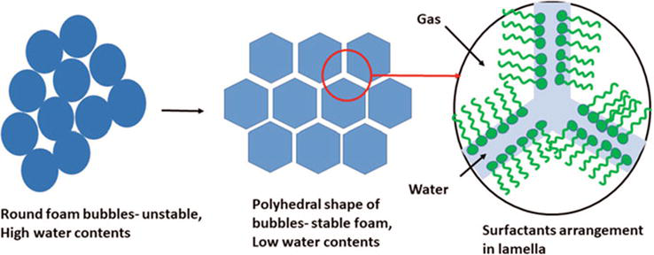
Foam texture refers to the physical appearance and structure of foam, which is a dispersion of gas bubbles in a liquid phase stabilized by surfactant molecules. It is impacted by the surfactant’s composition and concentration, pore structure, and injection rates. Based on the bubble structure, foam can be distinguished as spherical and polyhedral foam as shown in Figure 3 [24]. According to several previous investigations, spherical foam is a transient phase formed at the early stages of foam.
Figure 3.
Types of foam structures [24].
generation with thick lamella film, where foam is called wet foam with a higher proportion of liquid in comparison to gas content. However, polyhedral foam is a mature structure with thinner lamella film, and it is termed as dry foam as the water content is less than the gas content. On the other hand, based on the bubble size, foam is classified as coarse and fine [25]. In general, a foam with a coarse texture contains numerous large bubbles, also known as low-density foam, whereas a foam with a fine texture, referred to as high-density foam, is composed of a substantial number of small bubbles. Besides, coarse foam is generated at lower flow rates compared to fine foam generated at high flow rates. Several studies mentioned that spherical foam has smaller bubbles and more stable foam [26, 27] in contrast to polyhedral foam which possesses larger bubbles with less stability. Another opinion proposed that polyhedral foam is more stable compared to spherical foam [24].
2.3 Foam generation mechanisms
Foam generation in porous media is accompanied by the creation number of lamellae films. These lamellae are created through three main mechanisms as demonstrated in Figure 4.
Snap-off: It is the main mechanism for lamella creation in porous media. It occurs when a gas bubble becomes disconnected or snapped off from the continuous gas phase due to capillary forces or changes in pore geometry. As the gas bubble is disconnected, a thin liquid film wraps around it, creating a lamella. In fractured reservoirs, when gas is injected into the porous medium, it displaces the liquid phase (usually water or oil). As the gas advances, it can form elongated gas bubbles, and when certain conditions are met, these bubbles can become disconnected from the continuous gas phase. The process of snap-off occurs at pore throats or constrictions where the curvature of the gas–liquid interface is high. Capillary forces, which arise due to surface tension, act to minimize the surface area of the interface. When the curvature becomes too high, the capillary forces become dominant, and the gas bubble snaps off, leaving behind a liquid film that wraps around the bubble to form a lamella.
Leave-Behind: In the leave-behind mechanism, as the gas bubbles move through the porous medium, they leave behind liquid films on the pore walls. These liquid films coalesce to form lamellae around the gas bubbles.
Lamella Division: During foam flow through the porous medium, the lamellae can undergo division into smaller lamellae due to shear forces or interactions with the porous matrix. This process generates a higher number of lamellae and contributes to the stability of the foam.
Figure 4.
Mechanisms of foam generation in porous media [28].
Understanding the mechanisms behind lamella formation in porous media is essential for optimizing foam-based EOR strategies and achieving successful oil displacement and enhanced sweep efficiency. Researchers continue to explore these mechanisms to gain deeper insights into foam behavior and to develop more effective EOR techniques for various reservoir conditions.
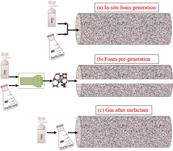
The selection of the most suitable foam generation technique depends on various factors, including reservoir properties, desired oil recovery goals, and operational considerations. Effective foam generation plays a crucial role in optimizing EOR processes and other applications that require efficient fluid displacement and mobility control. Several methods adopted by the industry and laboratory applications are summarized in Figure 5 as follows:
Figure 5.
Common foam generation methods.
3.1 Surfactant-alternating-gas (SAG)
This technique combines the advantages of surfactant injection with gas injection to create stable foams in the reservoir [29, 30]. Foam is formed inside the porous media by consecutive injection of gas and surfactant solution involving alternating cycles of surfactant injection and gas injection to create and maintain foam in the subsurface. This technique is alternatively known as “drainage foam” injection. Unlike traditional methods, foam generation using this approach is not confined solely to the entry zone. Instead, foam can be generated wherever there is contact between the gas and the invaded surfactant solution [30].
3.2 Foam pre-generation
This method involves the injection of a foam solution consisting of gas and a foaming agent into the oil reservoir. The foam is pre-formed before injection, which means it is generated at the surface or in a separate injection facility before being introduced into the reservoir [31]. The main findings of pre-generated foam injection for EOR include enhanced volumetric sweep efficiency, reduced gas mobility, and improved oil displacement, leading to higher oil recovery compared to conventional gas flooding methods, especially in fractured reservoirs. However, the success of this method depends on several factors such as reservoir properties, foaming agent selection, and injection parameters, which need to be carefully assessed and optimized for each reservoir to achieve the desired results. Furthermore, the properties of foam generated at the surface are different from foam in contact with porous media. It is crucial to ensure that the foam generated at the surface remains stable during injection, avoiding premature collapse or breaking down. As a result, there is a possibility of a gas breakthrough, where the gas phase separates from the liquid phase.
3.3 Co-injection
Co-injection method is another approach for foam generation. In this technique, both the gas and surfactant solution (foaming agent) are simultaneously injected into the reservoir through specific injection wells. The interaction of gas and surfactant at the subsurface conditions leads to the in-situ generation of foam, which aids in displacing and mobilizing the trapped oil [31]. During the co-injection foam process, monitoring techniques, such as tracer tests and pressure monitoring, are used to assess the performance and distribution of the foam in the reservoir. Adjustments in injection rates or surfactant concentrations may be made to optimize the process and maximize oil recovery.
This method offers several advantages, including increased oil recovery, better volumetric sweep efficiency, and the potential to mitigate gas mobility issues often encountered in conventional gas flooding processes. However, its applications in fractured reservoirs are limited and its successful implementation depends on understanding the reservoir characteristics and appropriately managing the injection parameters to achieve the best results.
3.4 In-situ co-injection in proppants
This technique resembles the co-injection foam process, where both the gas and the surfactant solution (foaming agent) are concurrently introduced into the reservoir. However, this approach is tailored specifically for fractured reservoirs to enhance the performance of foam. In essence, it involves the injection of proppants possessing specific characteristics into fractures, either naturally existing or created through hydraulic fracturing. This is done in conjunction with the simultaneous injection of foaming agents and gas, resulting in the generation of foam in situ [9, 32]. These proppants serve a dual purpose: they establish a porous medium that supports the formation of stable foam, and they adjust the fracture permeability for better fracture-matrix interactions. The strategic injection of proppants is particularly advantageous in the context of fractured reservoirs, encompassing diverse examples such as shale gas, tight oil, and coalbed methane reservoirs. However, thorough consideration and deliberate choice of the proppant variety, particle size distribution, and wetting characteristics emerge as critical factors to create more conducive conditions for effective foam generation. The selection of proppants should align with the specific reservoir’s characteristics and objectives, aiming to establish an environment that optimally supports in-situ foam generation processes.
3.5 Dissolved surfactant in gas phase
Based on various research findings, certain surfactants have demonstrated the ability to dissolve in carbon dioxide when subjected to supercritical conditions [33, 34]. In this innovative approach, the injection process involves introducing a single phase into the reservoir, and the foam is generated as soon as this phase comes into contact with the formation water. This unique method takes advantage of the surfactant’s solubility in supercritical carbon dioxide to simplify the injection process. Unlike traditional methods that require separate injections of gas and surfactant solutions, here, only one phase containing the surfactant is injected.
3.6 Simultaneous different layers
Several studies adopted this method to generate foam in the porous media where the gas phase and surfactant solution phase are injected simultaneously but in different layers of the well [35, 36]. In this method, the gas and surfactant solution are injected simultaneously, but in separate layers of the well. It is applicable to both vertical and horizontal wells. The gas injection occurs from the lower section or lower horizontal well, while the surfactant injection takes place from the upper section or upper horizontal well. The foam is generated inside the formation as a result of the natural separation caused by gravity, allowing the gas and surfactant phases to meet and interact.
Typically, foam stability is determined by the stability of lamellae film. The more stable the lamella film, the more stable the foam is, and vice versa. The stability of lamella film is controlled by several parameters such as pore geometry, experimental conditions, petrophysical properties, operating conditions, and surfactant formulation, and its concentration. These parameters shape the formation of bubbles, control gas diffusivity, disjoining pressure, and rate of capillary drainage.
4.1 Foam stability tests
4.1.1 Foamability
It measures how quickly foam generates by recording the pressure drop across porous media.
4.1.2 Foam half-life
The half-life of foam is the time it takes for the foam volume to reduce by half. This test assesses foam stability and longevity.
4.1.3 Foam apparent viscosity
It measures foam’s ability to control gas mobility. The foam’s apparent viscosity is typically determined using a rheometer, which measures the shear stress and shear rate applied to the foam sample. It also can be calculated using Darcy’s law in a fractured system, as shown in Eq. (1).
μf=Kf−o∗∆PfoamQg+QlAf∗LE1
where Kf−o is the absolute permeability of the fracture to oil, Af is the cross-sectional area of the fracture, Qg,Ql are the flow rates of the gas, and surfactant solution, respectively, and L is the length of the fracture.
4.1.4 Mobility reduction factor (MRF)
MRF is a critical parameter used to quantify the ability of foam to control gas mobility in porous media. It is calculated as the ratio of the gas mobility in the absence of foam to the gas mobility in the presence of foam as prescribed in Eq. (2).
MRF=∆Pfoam∆PnofoamE2
where ∆Pfoam is the steady-state pressure drop across the porous medium due to foam generation and ∆Pnofoamis the steady-state pressure drop without foam, i.e., co-injection of gas and brine (without surfactant).
4.2 Mechanisms of foam destabilization
Foam is destabilized by three underlying mechanisms including drainage, coarsening, and bubble coalescence. These mechanisms can lead to the breakdown of the foam structure and the reduction of foam stability:
Coalescence: It occurs when two or more gas bubbles come into contact and merge to form a single, larger bubble. This phenomenon can happen when the liquid films separating the gas bubbles become too thin or rupture due to drainage or external forces.
Coarsening: It is a gradual enlargement of gas bubbles in the foam over time. This occurs due to gas diffusion, where gas molecules migrate from smaller bubbles to larger ones. As smaller bubbles lose gas content, they shrink, while larger bubbles grow in size, leading to an increase in the average bubble size in the foam.
Drainage: It includes the movement of liquid within the foam structure. As the foam sits or flows, the liquid films between gas bubbles can drain and become thin due to gravity or pressure gradients.
4.2.1 Gas diffusion
Gas diffusion refers to the movement of gas molecules within the liquid phase of the foam. This diffusion can have both positive and negative effects on foam stability. On one hand, a positive effect (stabilizing Effect) in which gas diffusion can contribute to foam stability by replenishing the gas content in the liquid phase. As the gas diffuses from the continuous gas phase to the lamellae and liquid films surrounding the bubbles, it helps maintain the gas content within the foam structure. This process helps sustain the foam’s structure and prevents rapid bubble coalescence and foam collapse. On the other hand, a negative effect (gas Loss) where excessive gas diffusion can lead to gas loss from the foam structure. As gas molecules diffuse out of the foam into the surrounding liquid phase or porous matrix, the foam may lose its gas content, leading to the coalescence of the gas bubbles. This effect can be particularly pronounced in porous media with high gas permeability, where gas can easily escape from the foam structure.
4.2.2 Film drainage
In this mechanism, gravity causes the liquid inside the foam film to drain downward. Slowing down this drainage process can be achieved by increasing the bulk viscosity and reducing the liquid content of the foam. The time it takes for the lamella to reach critical thickness and the minimum thickness, leading to lamella coalescence, are crucial indicators of this process. These indicators depend on factors like surface elasticity, viscosity, gas-to-liquid ratio, surfactant solubility, and adsorption on the surface. Generally, the critical thickness diminishes as the surfactant concentration increases.
5. Factors affecting foam generation and stability
In fractured reservoirs, foam performance for EOR can be influenced by various parameters that impact foam generation, stability, and propagation through the fractures. Understanding these parameters is essential for optimizing foam-based EOR processes in such reservoirs. This can be achieved through laboratory experiments, reservoir simulation, and field trials resulting in a better understanding of the foam behavior and tailoring the EOR process to the specific reservoir conditions. Some of the key parameters affecting foam performance are considered below.
5.1 Fracture geometry
Fracture geometry plays a crucial role in influencing foaming ability, particularly in reservoirs with fractured formations. The geometry of fractures refers to their characteristics, such as aperture, orientation, connectivity, and distribution within the reservoir. These factors can significantly impact the behavior and efficiency of foam-based EOR techniques. Table 1 lists all the factors and their impacts on foam performance due to fracture geometry.
#
Parameter
Impact
1
Aperture
The aperture of fractures, which refers to the width or opening between the fracture surfaces, influences the flow velocity and pressure gradients within the fractures. Narrower apertures may hinder foam propagation and distribution, while wider apertures can facilitate easier foam flow.
2
Orientation
The orientation of fractures in relation to the injection wells and the reservoir’s geological features affects the direction of foam flow. Depending on the fracture orientation, foam may propagate more easily in certain directions, potentially leading to uneven oil displacement.
3
Fracture Connectivity
The connectivity of fractures determines how well they are interconnected within the reservoir. Well-connected fractures allow foam to propagate more effectively, covering a larger area and improving sweep efficiency.
4
Fracture Length and Width
Longer and wider fractures may influence foam transport and distribution. Longer fractures could lead to more extensive foam propagation, while wider fractures might accommodate more gas bubbles and stabilize the foam.
Table 1.
Factors arising from fracture geometry and their impact on foam performance.
By considering fracture geometry and its influence on foam transport in different directions, operators can tailor the injection strategy, foam composition, and operational parameters to achieve the best oil recovery results in such complex reservoirs.
5.2 Experimental conditions
This includes the pressure, temperature, and salinity of the reservoir. These conditions are critical factors that significantly influence foam performance in fractured reservoirs. They directly impact foam stability, propagation, and mobility control, which are vital for efficient oil displacement and improved recovery.
5.2.1 Operating pressure
Changes in reservoir pressure impact foam stability, foam generation, and gas solubility, ultimately affecting the efficiency of foam-based EOR techniques. In other words, at elevated pressures, the solubility of gas in the liquid phase decreases, leading to smaller gas bubbles and more stable foam. Stable foam can resist coalescence and collapse, ensuring its longevity and effectiveness in displacing oil. Furthermore, operating pressure directly affects the generation of foam. For instance, at higher pressures, foam can be more effectively generated due to reduced gas solubility in the liquid phase. This can lead to more efficient foam propagation through the reservoir. It can also facilitate easier foam flow and distribution in fractures, enhancing the foam’s contact with oil. In addition, higher pressure conditions often result in higher foam quality, where the gas phase occupies a larger fraction of the total foam volume. This can reduce gas mobility and delay gas breakthrough, leading to more uniform pressure fronts and better sweep efficiency. Last, high pressures can influence the capillary pressure of porous media and ensure the balance between foam stability and drainage.
5.2.2 Operating temperature
Reservoir temperature influences foam stability, gas solubility, viscosity, and phase behavior of the fluids within the reservoir, all of which can affect the effectiveness of foam performance in fractures. On one hand, the selection of a certain surfactant as a foaming agent is controlled by its susceptibility to temperature. It can impact surfactant adsorption at the gas–liquid interface and its ability to stabilize/destabilize the foam. Generally, lower temperatures favor foam stability as gas solubility decreases, leading to smaller gas bubbles and more stable foam. Higher temperatures can reduce foam stability by increasing gas solubility and promoting coalescence and bubble growth. In addition, changes in temperature can cause phase transitions in the reservoir fluids. For example, high temperatures may lead to gas condensation, altering the foam’s properties and stability. On the other hand, temperature plays a crucial role in determining the foam rheology where foam viscosity increases as the temperature decreases, resulting in increasing the mobility reducing factor and providing better flow front to block gas path and therefore, diverting gas to inaccessible oil-filled zones.
It is essential to consider the impact of operating temperature when designing and implementing foam EOR processes, especially in unconventional reservoirs with fractures. Monitoring and managing reservoir temperature during EOR operations can help optimize foam performance and overall oil recovery. Reservoir simulations and laboratory experiments under various temperature conditions can provide valuable insights into foam behavior, guiding the selection of suitable surfactants, injection strategies, and operational parameters for successful foam EOR operations in different temperature environments.
5.2.3 Salinity
The formation salinity has a significant impact on foam performance and is a crucial factor to consider when selecting the appropriate surfactant for Enhanced Oil Recovery (EOR) processes. Salinity refers to the concentration of dissolved salts, such as Sodium chloride (NaCl), Calcium chloride (CaCl2), Magnesium sulfate (MgSO4), Potassium chloride (KCl), etc. in the reservoir fluids. The salinity can vary widely from one reservoir to another and can fluctuate during production. The solubility of selected surfactants is affected by the salinity of the reservoir fluids. High salinity can lead to surfactant precipitation, reducing the amount of surfactant available to stabilize the foam. In extreme cases, surfactant precipitation may lead to the complete loss of foam stability. In addition, high salinity can increase the interfacial tension, making it more difficult for surfactants to reduce the tension and stabilize the foam. Moreover, salinity can affect the micellar phase behavior of surfactants. In some cases, high salinity may lead to the breakdown of micelles, causing foam destabilization. Depending on the surfactant formulation, salinity could be a stabilizer or destabilizer of the generated foam. Accordingly, selecting the appropriate surfactant for foam applications in a specific reservoir requires considering the salinity conditions. Surfactants with good salinity tolerance are essential for stable foam performance in high-salinity reservoirs. Compatibility between the surfactant and the reservoir fluid’s salinity is critical to ensure effective foam generation and stability. To this end, laboratory tests and reservoir simulation studies under various salinity conditions can help identify surfactants that are best suited for a particular reservoir’s salinity range.
5.3 Surfactant formulation
The effectiveness of foam stability, particularly in challenging reservoir conditions, heavily relies on the presence of strong adsorption at the gas/liquid interface of foam lamellae. Foaming agents, such as surfactants, play a crucial role in achieving this goal, as they are capable of generating stable foams. These surfactants can be categorized into anionic, cationic, nonionic, and zwitterionic (amphoteric) families, based on their surface charge. The presence of surface charge on the surfactant molecules leads to a dense packing at the gas bubble interface, resulting in increased charge density and electrostatic repulsion, which prevents lamella film drainage. This closer packing also affects the shear viscosity, contributing to better foam stability [37].
Generally, ionic and amphoteric surfactants are frequently utilized as foaming agents due to the charged lamellae they form. The overlap of similarly charged electric double layers (EDL) prevents film thinning, thereby enhancing foamability and extending foam’s half-life. On the other hand, nonionic surfactants lack electrical factors and are less effective at stabilizing foam [38].
Numerous studies have explored the impact of different surfactant solutions on foamability and foam stability. The findings regarding foamability are contradictory, with some studies favoring zwitterionic surfactants for better foamability, while others found nonionic surfactants to be more effective. One study even observed better foamability of anionic surfactants over zwitterionic ones [39]. In terms of stability, zwitterionic surfactants consistently exhibited higher foam half-lives compared to anionic surfactants.
The concentration of surfactant solutions also plays a significant role in foamability and foam stability. Studies have shown that foam properties depend on surfactant concentration and critical micelle concentration (CMC). Optimal foam properties are typically achieved at surfactant concentrations above CMC [40]. As the concentration increases, more surfactant molecules migrate to the liquid–gas interface, leading to a proportional increase in the initial foam height. Additionally, foam generated at concentrations above CMC exhibits a layering structure and reduced liquid film drainage. However, as surfactant concentration exceeds CMC, the foam’s half-life dramatically decreases. The excess surfactant molecules inside the lamellae increase the gravitational effect of the foam, resulting in easier lamella drainage and eventual rupture of the foam film. Thus, careful consideration of the optimum surfactant concentration is essential to avoid foam collapse at high concentrations [41]. Balancing surfactant concentration is crucial for achieving stable and long-lasting foam performance in EOR applications.
5.4 Gas type
A variety of gasses such as nitrogen (N2), carbon dioxide (CO2), hydrocarbon gases (methane (CH4) and/or produced formation gases), and air, have been utilized in many investigations to generate foam [42, 43, 44]. It is noteworthy that some studies have suggested comparable mobility reduction factor (MRF) between foams generated using nitrogen and hydrocarbon gases like CH4 [44]. However, other research has proposed that N2 may perform better in porous media while being comparable to CO2 and CH4 in micromodels [43]. These discrepancies highlight the importance of considering various factors, such as reservoir properties, foam generation techniques, and the specific EOR application, when selecting the most suitable gas for foam generation.
Generally, the choice of gas for a particular application depends on a multitude of factors, each playing a significant role in determining the most suitable option. Some of these factors include the availability of the gas at a reasonable cost, the specific conditions of the reservoir, the type of recovery scheme being employed (whether miscible or immiscible), the properties of the recoverable oil, and the overall economics of the entire process, among others. When considering the selection of gas for foam-based, it is essential to assess the availability of the gas in sufficient quantities and at a reasonable price. Some gases may be readily accessible in certain regions, while others might be scarce or come at a higher cost due to transportation or production expenses. The practicality of using a specific gas will depend on its local availability and affordability. Moreover, reservoir conditions play a crucial role in determining the compatibility of gas with the specific geology and fluid dynamics of the reservoir. Different gases may interact differently with the reservoir rock and fluids, impacting the efficiency and effectiveness of the EOR process. Understanding the reservoir’s unique characteristics is essential for choosing the most appropriate gas for foam generation or other EOR techniques.
5.5 Operating parameters
5.5.1 Injection rates
The injection rate influences the amount of gas that enters the porous media per unit of time. The higher the injection rates, the higher the pressure gradient, and the more gas enters the reservoir, increasing the potential for foam generation. Faster injection rates can lead to a higher gas fraction in the liquid phase, facilitating foam formation. However, at higher injection rates, there may not be enough time for foam drainage and film thinning between gas bubbles. As a result, gas bubbles may coalesce rapidly, leading to larger bubbles and destabilization of the foam structure. Furthermore, high rates can subject the foam to high shear forces, particularly at flow boundaries and around obstacles. These shear forces can disrupt the lamellae, which are the thin liquid films separating gas bubbles, leading to foam destabilization. Besides, extremely high injection rates can lead to large fluctuations in the pressure drop across the foam front. This sudden pressure drop can cause gas bubbles to expand rapidly, leading to foam instability and collapse. As a result, it must carefully select an optimal injection rate based on the specific reservoir conditions, foam formulation, and the desired objectives to avoid foam destabilization issued by injection rates.
5.5.2 Foam quality
The foam quality is a fraction of the foam volume containing gas. It can be defined when the relative amounts of gas and liquid are known. It is categorized into four regions based on the shape of foam bubbles, their interaction, and their effect on viscosity. In the first region (0–52% foam quality), spherical bubbles are uniformly dispersed without touching each other. In the second region (53–73% foam quality), the bubbles loosely arrange themselves in a cubical pattern, leading to increased viscosity during flow. The third region (74–95% foam quality) exhibits maximum foam viscosities, with bubbles forming parallel piped shapes. In the last region (above 95% foam quality), the foam is not stable as the liquid becomes the dispersed phase. Typically, foam regimes are classified into low-quality and high-quality regimes. In the low-quality regime, where the water fractional flow is high, bubble trapping and mobilization dominate the foam flow. As the gas fraction increases, the bubble volume increases, leading to drained lamellae films and collapse of the gas bubbles. This behavior occurs when the limiting capillary pressure (Pc*) is reached and is better known as the dry-out effect when foam texture is dryer and coarser.
5.6 Petrophysical properties
Foam generation in porous media is influenced by various petrophysical properties of the rock. These properties impact how foam behaves as it flows through the rock’s pore spaces, particularly in fractured reservoirs. Below are some of the properties that affect foam generation and its stability in porous media:
5.6.1 Rock wettability
Wettability is a fundamental physical property of reservoir rocks that has a significant impact on various parameters, including fluid distribution, relative permeabilities, capillary pressure, and residual oil saturation [27, 45]. It is influenced by factors such as rock mineralogy, fluid composition, saturation history, and reservoir temperature. Understanding wettability is crucial for predicting fluid behavior in reservoirs, optimizing production strategies, and designing enhanced oil recovery techniques. Wettability is proven to have a notable impact on foam generation and its stability in porous media. For instance, in water-wet rocks, where water has a higher affinity for the rock surface, foam generation is usually more favorable. This is because the presence of a water-wet surface facilitates the formation and stabilization of liquid films around the gas bubbles, promoting the stability of the foam structure. In oil-wet system, however, oil layer spreads over foam film resulting in collapsing lamella film. In addition, wettability impacts foam stability by influencing the drainage and coalescence of the gas bubbles. In water-wet rocks, the preferential wetting of the rock surface by the liquid phase (e.g., water) leads to slower drainage of liquid films between the gas bubbles. This reduced drainage can enhance foam stability as it prevents the gas bubbles from rapidly coalescing and merging, thus maintaining the foam structure for a longer time. Nevertheless, in oil-wet rocks, where oil has a higher affinity for the rock surface, foam generation and stability may be adversely affected. The presence of oil-wet surfaces can increase the resistance to foam flow, as the oil-wet rock may not provide the appropriate conditions for stable foam formation and propagation. This can lead to the breakdown of the foam structure and decreased foam stability.
5.6.2 Rock porosity and permeability
Fractured reservoirs are characterized by a complex network of interconnected fractures and matrix blocks, which introduce additional factors that influence foam behavior. Porosity and permeability have a double effect on foam performance. On one side, they affect the ease with which gas can flow through the porous media, and therefore, it directly impacts foam generation potential where higher permeability allows gas to flow more freely, making it easier to inject gas into the porous media and form gas bubbles, which are essential for foam formation. On the other side, porosity and permeability influence foam stability by affecting the drainage of liquid films between gas bubbles. In other words, in low-permeability media, the drainage of liquid films is slower, leading to more stable foam structures. This is because the liquid films have a longer residence time between gas bubbles, reducing the chances of rapid coalescence and bubble merging resulting in an improvement in the foam conformance and sweep efficiency during displacement processes. Accordingly, it is crucial to determine the optimum range of permeability that supports foam generation and also ensures the stabilization of gas bubbles.
5.6.3 Oil effect
The presence of oil has adverse effects on foam stability, making the detrimental impact prevailing. Surfactant interaction with oil causes liquid depletion in the thin liquid films (lamellae) that separate gas bubbles in the foam. Additionally, the presence of oil on the lamellae causes changes in rock wettability, and the spreading of oil disrupts the gas-water interface, leading to foam destabilization. Besides, the formation of an emulsion by the oil and surfactant solution further breaches the foam structure.
The mechanisms of foam stability against oil have been intensively studied, and Garrett proposed three coefficients to explain the oil’s destabilizing effects on foam: the entering coefficient (E), the spreading coefficient (S), and the bridging coefficient (B). These coefficients evaluate the feasibility of oil droplets entering the gas-water surface and interacting with the foam phase as prescribed in Eqs. (3), (4), and (5). Positive values for E indicate easy penetration of oil into the foam, while positive values for S and B suggest oil spreading over the lamellae and acting as a bridge between gas bubbles, respectively as displayed in Figure 6. These actions lead to coalescence and reduced stability of the foam structure.
Figure 6.
Mechanisms of foam/oil interactions [24].
E=σgw+σow−σogE3
S=σgw−σow−σogE4
B=σgw2+σow2−σog2E5
where, σgw,σow,andσog are the surface tension between water and gas, interfacial tension between oil and water, and surface tension between oil and gas, respectively.
Foam-based EOR can be a promising approach to enhance oil recovery and improve sweep efficiency in fractured systems. Fractured reservoirs present unique challenges due to their complex flow pathways, but foam-based processes offer several advantages in such environments. Foam can help address the mobility control issues caused by the presence of fractures, improve fluid distribution, and reduce the impact of channeling. Key findings and considerations for using foam EOR in fractured systems are:
Mobility Control: Foam serves as a mobility control agent, reducing the mobility of gas and improving the sweep efficiency in fractured reservoirs. It can divert the injected gas into the matrix, where it displaces oil effectively, leading to better interactions between the fractures and matrix and therefore, enhanced oil recovery.
Conformance Improvement: Foam can help mitigate the effects of permeability variations and fractures by improving conformance. It can divert gas into low-permeability zones and bypass high-permeability regions, and thus optimizing fluid displacement.
Foam Stability: Foam stability is crucial in fractured reservoirs. The interaction between foam and the rock surface, along with the presence of oil, can impact foam stability. Optimizing foam formulations and injection parameters is essential to maintain foam stability throughout the injection process.
Injection Strategy: The injection strategy, injection rates, foam quality, and experimental conditions play a significant role in foam performance in fractured systems. Properly designing the injection plan can help maximize foam sweep efficiency and minimize foam destabilization.
Reservoir Characterization: Detailed reservoir characterization, including fracture mapping and permeability measurements, is essential to understand the fractured system’s heterogeneity. This information guides the design of effective foam injection plans.
The author would like to acknowledge the University of Wyoming and the Center of Innovation for Flow through Porous Media for their support to gain knowledge and access to resources.
The author declares that they have no known competing financial interests or personal relationships that could have appeared to influence the work reported in this chapter.
References
1.Liu G, Sorensen JA, Braunberger JR, Klenner R, Gorecki CD, Steadman EN. CO2-based enhanced oil recovery from unconventional reservoirs: A case study of the Bakken formation. In: SPE Unconventional Resources Conference/Gas Technology Symposium. The Woodlands, Texas, USA; 2014. DOI: 10.2118/168979-MS
2.Kang WL, Zhou BB, Issakhov M, Gabdullin M. Advances in enhanced oil recovery technologies for low permeability reservoirs. Petroleum Science. 2022;19:1622-1640. DOI: 10.1016/j.petsci.2022.06.010
3.Park H, Park Y, Lee Y, Sung W. Efficiency of enhanced oil recovery by injection of low-salinity water in barium-containing carbonate reservoirs. Petroleum Science. 2018;15:772-782. DOI: 10.1007/s12182-018-0244-z
4.Liu P, Zhang X, Hao M, Liu J, Yuan Z. Parameter optimization of gas alternative water for CO2 flooding in low permeability hydrocarbon reservoirs. Journal of Renewable and Sustainable Energy. 2016;2016:8. DOI: 10.1063/1.4948483
5.Muther T, Qureshi HA, Syed FI, Aziz H, Siyal A, Dahaghi AK, et al. Unconventional hydrocarbon resources: Geological statistics, petrophysical characterization, and field development strategies. Journal of Petroleum Exploration and Production Technologies. 2022;12:1463-1488. DOI: 10.1007/s13202-021-01404-x
6.Schön JH. Rocks their classification and general properties. Developments in Petroleum Science. 2015;65:1-19. DOI: 10.1016/B978-0-08-100404-3.00001-9
7.Shojaei AK, Shao J. Application of continuum damage mechanics in hydraulic fracturing simulations. In: Porous Rock Fracture Mechanics: With Application to Hydraulic Fracturing, Drilling and Structural Engineering. Switzerland: Springer Nature; 2017. pp. 197-212. DOI: 10.1016/B978-0-08-100781-5.00009-9
8.Gandossi L, Von Estorff U. An overview of hydraulic fracturing and other formation stimulation technologies for shale gas production. In: European Commission Joint Research Center Technical Reports. Luxembourg; 2013. p. 26347. DOI: 10.2790/379646
9.Youssif MI, Sharma KV, Piri M. Hydrocarbon gas foam injection in fractured oil-wet carbonate samples: An experimental investigation of the effect of fracture-matrix permeability contrast on oil recovery. In: SPE Canadian Energy Technology Conference. Calgary, Alberta, Canada; 2023. DOI: 10.2118/212736-MS
10.Le VS, Sharma KV, Hanamertani AS, Youssif MI, Elkhatib O, Rane K, et al. Methane foam performance in oil-wet unconsolidated porous media: A systematic experimental investigation at reservoir conditions. Fuel. 2023;344:128002. DOI: 10.1016/j.fuel.2023.128002
11.Wellington SL, Vinegar HJ. Surfactant-induced mobility control for carbon dioxide studied with computerized tomography. ACS. 1988;1988:344-358. DOI: 10.1021/bk-1988-0373.ch017
12.Boerrigter PM, Verlaan ML, Yang D. EOR methods to enhance gas oil gravity drainage modeling aspects. In: Society of Petroleum Engineers - SPE/EAGE Reservoir Characterization and Simulation Conference. Abu Dhabi, UAE; 2007. pp. 219-227. DOI: 10.3997/2214-4609-pdb.24.b20
13.Wang L, Tian Y, Yu X, Wang C, Yao B, Wang S, et al. Advances in improved/enhanced oil recovery technologies for tight and shale reservoirs. Fuel. 2017;210:425-445. DOI: 10.1016/j.fuel.2017.08.095
14.Rossen WR, van Duijn CJ. Gravity segregation in steady-state horizontal flow in homogeneous reservoirs. Journal of Petroleum Science and Engineering. 2004;43:99-111. DOI: 10.1016/j.petrol.2004.01.004
15.Le Van S, Youssif MI, Hanamertani AS, Sharma KV, Elkhatib O, Rane K, et al. Methane foam performance evaluation in water-wet unconsolidated porous media: A systematic experimental investigation at elevated pressure and temperature conditions. Journal of Natural Gas Science and Engineering. 2022:104835. DOI: 10.1016/j.jngse.2022.104835
16.Hanssen JE. Foam processes: An assessment of their potential in North Sea reservoirs based on a critical evaluation of current field experience. In: SPE Improved Oil Recovery Conference. Tulsa, Oklahoma, USA; 1994. DOI: 10.2118/27768-MS
17.Zhu T, Ogbe DO, Khataniar S. Improving the foam performance for mobility control and improved sweep efficiency in gas flooding. Industrial and Engineering Chemistry Research. 2004;43:4413-4421. DOI: 10.1021/ie034021o
18.Hirasaki GJ, Lawson JB. Mechanisms of foam flow in porous media: Apparent viscosity in smooth capillaries. Society of Petroleum Engineers Journal. 1985;1985:25. DOI: 10.2118/12129-PA
19.Kovscek AR, Radke CJ. Fundamentals of foam transport in porous media. Advances in Chemistry. 1993;1993. DOI: 10.2172/10192736
20.Farajzadeh R, Lotfollahi M, Eftekhari AA, Rossen WR, Hirasaki GJH. Effect of permeability on implicit-texture foam model parameters and the limiting capillary pressure. Energy and Fuels. 2015;29:3011-3018. DOI: 10.1021/acs.energyfuels.5b00248
21.Rossen WR. Foams in enhanced oil recovery. In: Foams: Theory, Measurements, and Applications. 1996. DOI: 10.1201/9780203755709
23.Gauglitz PA, Friedmann F, Kam SI, Rossen WR. Foam generation in homogeneous porous media. Chemical Engineering Science. 2002;57:4037-4052. DOI: 10.1016/S0009-2509(02)00340-8
24.Sagir M, Mushtaq M, Tahir MS, Tahir MB, Shaik AR. Foams in EOR. In: Surfactants for Enhanced Oil Recovery Applications. Switzerland: Springer International Publishing; 2020. pp. 41-63. DOI: 10.1007/978-3-030-18785-9_3
25.Ibrahim KZ, Adebayo AR, Isah A, Muhammed NS. A literature review of strength and stability of foam and their relationship with the absolute permeability of porous media. Journal of Petroleum Science and Engineering. 2022;2022:211. DOI: 10.1016/j.petrol.2022.110195
26.Audebert A, Beaufils S, Lechevalier V, Le Floch-Fouéré C, Saint-Jalmes A, Pezennec S. How foam stability against drainage is affected by conditions of prior whey protein powder storage and dry-heating: A multidimensional experimental approach. Journal of Food Engineering. 2019;242:153-162. DOI: 10.1016/j.jfoodeng.2018.08.029
27.Schramm LL, Mannhardt K. The effect of wettability on foam sensitivity to crude oil in porous media. Journal of Petroleum Science and Engineering. 1996;15(1):101-113. DOI: 10.1016/0920-4105(95)00068-2
28.Risal AR, Manan MA, Yekeen N, Azli NB, Samin AM, Tan XK. Experimental investigation of enhancement of carbon dioxide foam stability, pore plugging, and oil recovery in the presence of silica nanoparticles. Petroleum Science. 2019;16:344-356. DOI: 10.1007/s12182-018-0280-8
29.Alcorn ZP, Fredriksen SB, Sharma M, Føyen T, Wergeland C, Fernø MA, et al. Core-scale sensitivity study of CO2 foam injection strategies for mobility control, enhanced oil recovery, and CO2 storage. In: E3S Web of Conferences. Vol. 146. France: EDP Sciences; 2020. DOI: 10.1051/e3sconf/202014602002
30.Rossen WR, Boeije CS. Fitting foam simulation model parameters for SAG foam applications. In: SPE Enhanced Oil Recovery Conference. Kuala Lumpur, Malaysia; 2013. DOI: 10.2118/165282-MS
31.Turta AT, Singhal AK. Field foam applications in enhanced oil recovery projects: Screening and design aspects. Journal of Canadian Petroleum Technology (Canada). 2002;41(10). DOI: 10.2118/02-10-14
32.Youssif MI, Sharma KV, Piri M. Performance evaluation of innovative foam assisted gas injection schemes on propped-fractured oil-wet carbonate rocks at high-temperature and high-pressure conditions. Fuel. 2023;2023
33.Le VQ, Nguyen QP. A novel foam concept with CO2 dissolved surfactants. In: SPE Improved Oil Recovery Conference. Tulsa, Oklahoma, USA; 2008. DOI: 10.2118/113370-MS
34.Ashoori E, Van Der Heijden TLM, Rossen WR. Fractional-flow theory of foam displacements with oil. SPE Journal. 2010;15(02):260-273. DOI: 10.2118/121579-PA
35.Stone HL. A simultaneous water and gas flood design with extraordinary vertical gas sweep. In: SPE International Petroleum Conference in Mexico. Puebla Pue, Mexico; 2004. DOI: 10.2118/91724-MS
36.Rossen WR, Vikingstad AK. Injection strategies to overcome gravity segregation in simultaneous gas and water injection into homogeneous reservoirs. SPE Journal. 2010;15(01):76-90. DOI: 10.2118/99794-PA
38.Chang Q. Emulsion, foam, and gel. In: Colloid and Interface Chemistry for Water Quality Control. London: Chemical Industry Press; 2016. pp. 227-245. DOI: 10.1016/B978-0-12-809315-3/00011-6
39.Boeije CS, Rossen WR, Vad Bennetzen M. A methodology for screening surfactants for foam enhanced oil recovery in an oil-wet reservoir. SPE Reservoir Evaluation and Engineering. 2017;20:795-808. DOI: 10.2118/185182-pa
40.Lee J, Nikolov A, Wasan D. Foam stability: The importance of film size and the micellar structuring phenomenon. Canadian Journal of Chemical Engineering. 2014;92:2039-2045. DOI: 10.1002/cjce.22071
41.Wang H, Chen J. A study on the permeability and flow behavior of surfactant foam in unconsolidated media. Environment and Earth Science. 2013;68:567-576. DOI: 10.1007/s12665-012-1760-6
42.Andrianov A, Farajzadeh R, Mahmoodi NM, Talanana M, Zitha PLJ. Immiscible foam for enhancing oil recovery: Bulk and porous media experiments. Industrial and Engineering Chemistry Research. 2012;51:2214-2226. DOI: 10.1021/ie201872v
43.Xu Z, Li B, Zhao H, He L, Liu Z, Chen D, et al. Investigation of the effect of nanoparticle-stabilized foam on EOR: Nitrogen foam and methane foam. ACS Omega. 2020;5:19092-19103. DOI: 10.1021/acsomega.0c02434
45.Mannhardt K, Svorstøl I. Effect of oil saturation on foam propagation in snorre reservoir core. Journal of Petroleum Science and Engineering. 1999;23:189-200. DOI: 10.1016/S0920-4105(99)00016-9
Written By
Magda Ibrahim Youssif
Submitted: 26 July 2023Reviewed: 03 August 2023Published: 20 October 2023
 Open access peer-reviewed chapter