 Open access peer-reviewed chapter
Abstract
The term of toughness is one of the fracture parameters which describes the ability of structures to remain deformed while collapsing. Toughness can be expressed as both, strain energy release rate G or as stress intensity factor K. This study deals with how reinforcement influences toughness K to divert rapid to gradual failure. Wedge forces developed by cohesiveness between rebars and concrete are the main concern in transforming elastic to plastic behavior by means reducing the value of stress intensity factor K. Three-point bend beam as a specimen with mode I fracture of (150 × 300) mm dimension with 100 mm initial crack was conducted in the analytical processing. The specimen was reinforced by 4#12mm steel bars. Wedge forces ‘p’ due to reinforcement tensile T developed by composite action between concrete and reinforcement prevailed
Keywords
- fracture mechanics
- toughness
- stress intensity factor
- wedge forces
- reinforced concrete beam
1. Introduction
Concrete is well known as discrete material which is full of cracks. This condition occurs due to some reason, such as imperfection during the mixing of its constituent, casting and curing process as well [1].
This unfortunate initial condition prevails to decrease the ability of toughness performance after elastic limit is achieved. Cementitious material such as concrete with relatively high discretization is weak to the separation (fracturing) between the constituent grains. Therefore, in assessing its structural capacity, it needs to be specially formulated by taking into account the possibility of developing fracture process zone - FPZ at the crack tip through toughness vice versa [2, 3, 4]. The development of material technology has brought the ‘world of science’ to develop up-to-date concepts related to effective and efficient structural capacities which mean that a structural design must fulfill safe and economical aspects. Applying this idea, structural failure should be perceived based on both strength criteria and fracture mechanics view of point.
Mathematically, failure mechanism which is based on the principles of fracture mechanics can be expressed as total potential energy, that is
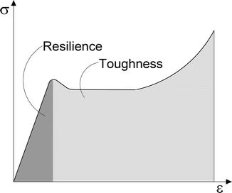
Figure 1.
Wedge forces of a single crack reinforced beam.
2. Review
2.1 Toughness
Structures under loading will undergo two basic stages of deformation, namely ‘elastic’ and ‘plastic’. Elastic is a phenomenon where deformation will return to its original shape when load is removed. While plastic is post elastic deformation, yielding or semi yielding or quasi-brittle depends on material characteristic. To get a clear picture of these two phenomena, consider the load deformation relationship in Figure 2 [7].
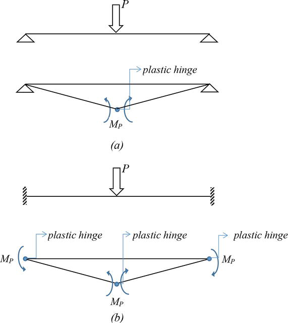
Figure 2.
Resilience vs Toughness [
The area up to the yield point is known as resilience or elastic range, while area beyond the elastic limit up to ultimate point at which failure occurs is known as toughness. Based on the concept of fracture mechanics, resilience describes energy consumed during loading, but toughness is energy dissipated while fracture propagation in progress/occurs.
In addition, toughness can be analogous to ductility in yielding materials.
2.2 Structural collapse capacity
Structural collapse can be defined as a condition where structures can no longer able to withstand load. This phenomenon is the starting point on which capacity design is based. Referring to the concepts of fracture mechanics, structural collapse capacity can be assessed by studying the possibility of FPZ propagation (at sectional level) followed by the formation of plastic hinges (at structural level). Please keep in mind that fracture zone is a term of damage zone performed at the crack tip when a beam is loaded beyond its elastic limit [8]. By considering the illustration in Figure 3, it can be proved analytically that a beam with free rotation supports shown in Figure 3a does not have toughness as high as a beam with fixed support shown in Figure 3b. Plastic hinges are components which enable to dissipate energy as fracture propagation occurs. This phenomenon is potential to divert brittle fracture caused by the absence of toughness into a gradual failure due to the presence of toughness.

Figure 3.
Illustration, structural collapse capacity described by plastic moment MP (a) Beam with end free rotation supports – 1 plastic moment MP. (b) Beam with end fix support – 3 plastic moment MP.
Toughness index rules the performance of collapse mechanism. Resilience refers to ‘strength’ in the elastic range before collapse, while toughness refers to the ability of structures to ‘deform’ before collapse.
2.3 Stress intensity factor
The term ‘stress intensity factor SIF is one of the fracture parameters; it describes stress intensity around the crack tip, which is represented by variable
Developed in 1957 by Irwin [9],
where σ = remote stress applied to the component; a = crack length; f(g) = correction factor that depends on specimen and crack geometry.
In case of three-point bend beam shown by Figure 4, Eq. (1) can be re-written as [5]
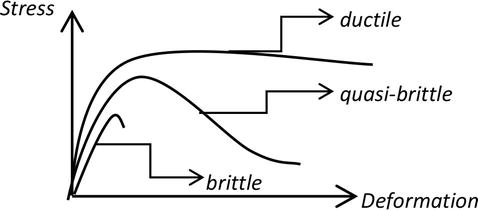
Figure 4.
Three point mode I fracture beam.
where a = length of initial crack; b = depth of beam; t = thick of beam;
The remote stress
To avoid structures from brittle fracture, the value of
2.4 How steel bars reducing K
In principle, failure of concrete begins with the collapse of the material due to its inability to expand the composite action between matrix and aggregates. It is highly recommended to understand that the interface zone rules a role in such a case. In plain concrete, aggregates have the potential to function as reinforcement which reinforces matrix. Steel bars play the same role at higher level, namely reinforced concrete. Due to steel bars reinforcement, the accumulated stress intensity at the crack tip can be reduced prevails a stable fracture failure mechanism. This is what the concept of ductility underlies especially in earthquake-resistant structures. Reinforcement is a driving force that generates composite action between rebars and concrete, and hence, it is able to divert the brittle failure gradually to quasi-brittle and finally to ductile, as shown in Figure 5.
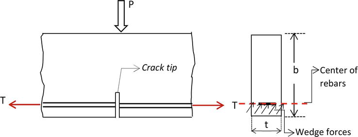
Figure 5.
Wedge forces of a single crack reinforced beam.
2.5 Fracture toughness of concrete
Fracture toughness can be clarified as both, critical strain energy release rate denoted by
Concrete is considered as a quasi-brittle material whose failure mechanism might be expressed by the compatibility between the energy absorbed when loading and energy released when unloading. Please be noticed that in case of crack propagation, unloading occurs simultaneously with crack propagation for quasi-brittle materials, analog with yielding process for ductile materials [3, 10].
2.6 Wedge forces of single cracked element
Concrete is a material with a high sensitivity to notches. If it is subjected to a tensile force, e.g., bending reinforced concrete beam shown in Figure 1, then cracking propagation will occur and that starts from the crack tip at the moment when tensile stress due to loading exceeds its tensile strength.
In case of under-reinforced or over-reinforced concrete beam one can visualize an extreme mode of failure known as brittle fracture mechanism which has to be avoided especially in case of dynamic loads. Reinforced concrete with adequate reinforcement ratio is able to develop wedge forces due to composite action between reinforcement and concrete. Under such condition, beam will collapse slowly as the fracture process forms at the crack tip…known as being tough [1, 3, 11]. This study examines how reinforcement reduced the stress intensity factor SIF and simultaneously increase toughness.
3. Case study
A reinforced concrete beam of (150 × 300) mm2 dimension with span S = 1000 mm was subjected to a centralized load P at the middle span. A beam with a single tensile crack was made of concrete material with properties given as follows [7]
Compressive strength
Fracture toughness
Modulus of elasticity of steel bar
Yield strength of steel bar
If the initial crack a = 100 mm, with 4≠12 mm reinforcement, this study was conducted to investigate whether the reinforcement is sufficient to reduce the stress intensity factor KI at the crack tip so, the brittle failure can be diverted to quasi-brittle or even to ductile/plastic failure. Please note that
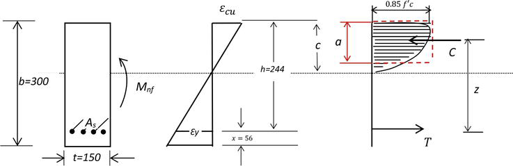
Figure 6.
Strain and stress distribution under bending.
3.1 Step I: checking the reinforcement ratio
T is the tensile force developed by the reinforcement. The minimum amount of reinforcement should be provided such that the first cracking of concrete and yielding of steel occurs simultaneously [11].
Bosco et al proposed a brittleness number corresponding to a transition between ductile (
found,
Maximum ratio may be calculated using the basic formula as
found,
The results shown that
3.2 Step II: determination of neutral axis
By assuming that plane section remains plane after deformation, a linear distribution of strain over the beam depth was obtained.
Neutral axis is determined based on the linear strain relationship in Figure 6.
If the ultimate strain of concrete
3.3 Step III: determination of moment capacity M nf
Force equilibrium
T
= Asfy = 266774.4 Nz =
= 62417206.62 Nmm
3.4 Step IV: determination of stress intensity factor due to P
Remote stress due to P [5]
or,
Applied to ultimate condition where
3.5 Step V: toughness contributed by reinforcement
Wedge forces
Refering to Green Function, stress intencity factor due to average stress over the crack line [12]
here, x = 56 mm was the distance between center of reinforcement and the outer tension fiber of the beam.
found,
Wedge forces due to reinforcement T was:
Then,
Reinforcement contribution to
4. Discussion
Resume of analysis results
The critical stress intensity factor,
The stress intensity factor due to wedge forces T,
The stress intensity factor due to the external load P,
Based on the principle of total potential energy [5], the stress intensity factor due to the contribution of reinforcement is equal to
Without reinforcement, stress intensity factor
The results of the analysis shown that due to reinforcement presence, crack propagation still occurs under a value of stress intensity factor
This fact implies that brittle failure dealing with
5. Conclusion
Concrete as a discrete material tends to be full of cracks leading to rapid failure mechanism.
Rapid failure mechanism can be diverted to quasi-brittle mechanism by performing fracture process zone FPZ, at the crack tip, resulting to softening type of load-deformation relationship.
By adding reinforcement, the FPZ will become more solid resulting in toughness improvement and energy dissipation.
Toughness is one of the most prominent fracture parameters on which structural capacity can be defined.
References
- 1.
Leonhardt F. Crack and crack control in concrete structures. PCI Journal. 1988; 33 (4):124-145 - 2.
Rama Chandra Murthy A, Palani GS, Iyer NR. State of the art review on fracture analysis of concrete structural components. 2009; 345–367 - 3.
Patty AH. The effect of reinforcement bridging on the elastic fracture energy of concrete. Material Science and Engineering. 2019; 669 . DOI: 10.1088/1757-899X/669/1/012019. (Open access file) - 4.
Bhowmik S, Ray S. An experimental approach for characterization of fracture process zone in concrete. Engineering Fractures Mechanics. 2019; 2019 :401-419. DOI: 10.1016/engfreacmech.2019.02.026 - 5.
Shah SP, Swartz SE, Ouyang C. Fracture Mechanics of Concrete. USA: John Wiley & Sons, Inc; 1995 - 6.
ACI Committee 446.1R-91. Fracture mechanics of concrete: Concepts, models and determination of material properties. 1989 - 7.
Roylance D. Mechanics of Material. USA: John Wiley & Sons, Inc; 1996 - 8.
Hoover CG, Bazant ZP, Wendner R, Vorel J, Hubler MH, Kim K, et al., editors. Experimental Investigation of Transitional Size Effect and Crack Length in Concrete Fracture: Life-Cycle and Sustainability of Civil Infrastructure Systems. London: Taylor & Francis Group; 2013 - 9.
Irwin GR. Analysis of stresses and strains near the end of a crack traversing a place. Journal of Applied Mechanics. 1957; 24 :361-364 - 10.
Zdenek PB. Concrete fracture models: Testing and practice. Engineering Fractures Mechanics. 2022; 2022 :165-205 - 11.
Bosco C, Carpinteri A, Member ASCE, Debernardi PG. Minimum reinforcement in high strength concrete. Journal of Structural Engineering. 1990; 1990 :427-437 - 12.
Cartwright DJ, Rooke DP. Green Functions in Fracture Mechanics. Future Prospects, University of Cambridge; 1979 - 13.
Ricardo AE, Velasco MSL. Fracture parameters for high-performance concrete. Cement and Concrete Research. 2006; 36 :576-583. DOI: 10.1016/j.cemconres.2005.09.004